2002 Hyundai Grandeur fuel
[x] Cancel search: fuelPage 188 of 230

DO-IT-YOURSELF MAINTENANCE 6- 11
G060B03L-GAT
Replacing the Spark Plugs
The spark plugs should be changed
at the intervals specified in the ve- hicle maintenance schedule in Sec- tion 5 or whenever engine perfor- mance indicates they should bechanged. Symptoms that suggest poor spark plug performance include en- gine misfiring under load, loss of fueleconomy, poor acceleration, etc. When spark plugs are replaced, al- ways use spark plugs recommendedby Hyundai. The use of other spark plugs can result in loss of perfor- mance, radio interference or enginedamage.
NOTE:
o When replacing the spark plug, Genuine Hyundai ReplacementParts are recommended. Recommended Spark Plugs:
NOTE: Do not clean or regap platinum- tipped spark plugs.
o Spark plugs should be tightenedfirmly. Overtightening can dam- age the threads in the aluminum cylinder head. Also, leavingthem too loose can cause the spark plug to get very hot and posibly result in damage to theengine.
o It is recommended that the spark plug should be changed by anauthorized Hyundai dealer.
!
3.5L/3.0L
2.5L
3.5L/3.0L 2.5L
Type
RC10PYP4(CHAMPION) RC10PYPB4(CHAMPION) PFR5N-11(NGK) RC10PYPB4(CHAMPION) PFR5N-11(NGK) RC10YC4(CHAMPION) BKR5ES(NGK)
Remark
Un-
leaded
LeadedWARNING:
It is recommended that the engine be cool or cold when changing the spark plugs. If the engine is hot,you could burn yourself on the insulated connector, the spark plug or the engine itself.
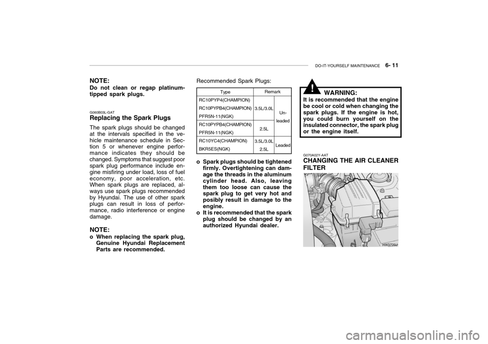
G070A02Y-AAT CHANGING THE AIR CLEANER FILTER
HXG720J
Page 202 of 230

DO-IT-YOURSELF MAINTENANCE 6- 25
G290A02L-GAT
HEADLIGHT AIMING ADJUST- MENT
HID Type (If installed)
WARNING:
If you need headlight aiming ad- justment, have your vehicle in- spected by your Hyundai Dealer. Don't attempt to replace or inspect the HID headlight bulb to prevent danger of an electric shock.
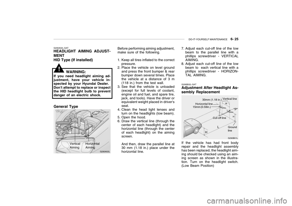
Vertical Aiming HorizontalAiming
Before performing aiming adjustment, make sure of the following.
1. Keep all tires inflated to the correct pressure.
2. Place the vehicle on level ground
and press the front bumper & rear bumper down several times. Place the vehicle at a distance of 3 m (118 in.) from the test wall.
3. See that the vehicle is unloaded (except for full levels of coolant,engine oil and fuel, and spare tire,jack, and tools). Have the driver or equivalent weight placed in driver's seat.
4. Clean the head light lenses and
turn on the headlights (low beam).
5. Open the hood.
6. Draw the vertical line (through the center of each headlight) and the horizontal line (through the center of each headlight) on the aimingscreen. And then, draw the parallel line at 30 mm (1.18 in.) place under the horizontal line.
!
G290B02L-GAT
Adjustment After Headlight As- sembly Replacement
G290B01L
LW
H
H Cut-off line
Ground line
If the vehicle has had front body repair and the headlight assembly has been replaced, the headlight aim-ing should be checked using an aim- ing screen as shown in the illustra- tion. Turn on the headlight switch.(Low Beam Position)
"P"
Horizontal line15mm (0.59in.)
30mm (1.18 in.) Vertical line
7. Adjust each cut-off line of the low
beam to the parallel line with a phillips screwdriver - VERTICALAIMING.
8. Adjust each cut-off line of the low
beam to each vertical line with a phillips screwdriver - HORIZON- TAL AIMING.
G290A02L
General Type
Page 211 of 230

6- 34 DO-IT-YOURSELF MAINTENANCE
G200C01L-GAT JUNCTION BOX DESCRIPTION Under Hood Junction Box
G200C01L
NOTE: Not all junction box description in this manual
may be applicable to your vehicle. It is accurate at the time of printing. When you inspect the junction box on your vehicle, refer to the junction box label. DESCRIPTION
FUEL PUMP
HEAD LIGHT(Lo-LH) ABS
INJECTOR
A/C COMPRESSOR A/T
MAIN
IGNITION COIL
OXYGEN SENSOR EGR
HORN
HEAD LIGHT(HI)
HEAD LIGHT(Lo-RH) DRL
FOG LIGHT DIODE 1
SPARE
SPARE
SPARE
SPARE
DIODE 2
BLOWER
POWER FUSE 2 POWER AMPSUNROOF
TAIL LIGHT
POWER FUSE 1 ECU
REAR DEFOGGER CONDENSER
POWER WINDOW IGNITION1/2ABS 1/2
RADIATOR FUSE
RATING
20A15A10A10A10A20A30A 20A 15A 15A10A15A20A15A15A 30A 20A15A10A 30A 30A20A15A20A30A10A30A20A40A
30A/30A30A/30A 30A PROTECTED COMPONENTS
Fuel pump relay
Head light relay (Low-LH)
ABS controls, Cruise control module, ETS control module
Limp home valve, ETS controls, Injector
A/C relay
A/T control relay, TCM, Engine control relayMFI controls
Ignition coil, A/T pulse generator, ECM, Ignition failure
sensor, E/TCM
ETS relay, MFI controls
A/C relay, MFI controls, EGR solenoid
Horn relay
Head light relay (High)
HID head light relay
DRL control module, Siren
Fog light relay - -----
Blower relayFuse 4, 20, 24, 25
Audio amp module
Data link connector, Sunroof relay, Home link connector
Tail light relayFuse 1, 7, 17, 18, 19
ETS control module, ECM, E/TCM, Generator
Rear window defogger relay
A/C fan relay #1
Power window relay, IMS controls
Ignition switchABS controlsRadiator fan relay
Page 212 of 230

DO-IT-YOURSELF MAINTENANCE 6- 35
FUSE RATING
25A 20A10A15A10A10A10A15A10A10A15A 10A 10A 10A20A10A 15A 10A15A10A10A15A10A20A 10A 10A 10A 10A10A10A 10A 10A PROTECTED COMPONENTS
Power seat
Seat warmerEPS controls
ETS relay
(HID) Head lights, DRL controls, AQS sensor
Blower & A/C controls
Turn & Hazard controlsNot used
Cruise switch, Instrument cluster
Head light leveling switch, Rain sensor, IMS controls
Rain sensor relay, Wiper & Washer controls
Home link connector, Left (Right) vanity lights, Sunroof, Blower & A/C controls,Electronic chrome mirrorNot used
Audio
Front (Rear) cigarette lighter, Accessory socket
IMS controls, Driver door module, RheostatNot used
Rear for light relay
Stop lights, Left (Right) personal lights, Left (Right) rear door lights
Door warning & Ignition key illumination, Courtesy lightsInstrument clusterSRS controls
Automatic transaxle controls, Back-up light switch, Vehicle speed sensor
Fuel filler door & Trunk lid opener, Driver (Assister) door module
Multipurpose check connector, Audio, lmmobiilizer controls, Trip computers, Digital
clock, Blower & A/C controls, Instrument cluster
Left (Right) inside lights, (HID) Head lights, Fog light relay, Right HID turn signal light,Right rear combination light
Stop light failure relay
Immobilizer controls, TCS switch, Trip computers, Instrument cluster
ETACM, Hazard switch, Auto light sensor
Antenna, Blower & A/C controls, Left (Right) outside mirror motor & Folding motor
(HID) Head lights, Front (Rear) cigarette lighters, Left (Right) license lights, Left HID
Turn signal light, Left rear combination lightBurglar alarm relay, Transaxle range switch, Start relay, ETS controlsDESCRIPTION P/SEAT
S/HTR EPSETS
H/LP
A/CON SW HAZARDSPARE
CRUISE IMS
WIPER
ETACS
SPARE AUDIO
C/LIGHTER MIRRORSPARE
RR FOG
STOP LP
ROOM LP
A/BAG IND A/BAGB/UP
T/LID
D/CLOCK
RH TAILSPARE
CLUSTER T/SIG
RR HTD IND
LH TAIL
START
G200D01L-GAT
Instrument Panel Junction Box
G200D01L
Page 214 of 230

7- 2 EMISSION CONTROL SYSTEMS
H010A01A-GAT
EMISSION CONTROL SYSTEM (If Installed)
Your Hyundai is equipped with an
emission control system to meet all requirements of the Emission prohibi-tion rules of your province.
There are three emission control sys-
tems which are as follows.
1) Crankcase emission control sys-
tem
2) Evaporative emission control sys-
tem
3) Exhaust emission control system
In order to assure the proper function
of the emission control systems, it is recommended that you have your car inspected and maintained by an au-thorized Hyundai dealer in accordance with the maintenance schedule in this manual. H010B01A-AAT
1. Crankcase Emission Control
System
The positive crankcase ventilation
system is employed to prevent airpollution caused by blow-by gasesbeing emitted from the crankcase. This system supplies fresh air to the crankcase through the air intake hose.Inside the crankcase, the fresh air mixes with blow-by gases, which then pass through the PCV valve and intothe induction system.
H010C02Y-GAT
2. Evaporative Emission
Control System
The Evaporative Emission Control
System is designed to prevent fuel vapors from escaping into the atmo- sphere. Canister
While the engine is inoperative, fuel
vapors generated inside the fuel tank are absorbed and stored in the canis- ter. When the engine is running, the fuel vapors absorbed in the canisterare drawn into the induction system through the purge control solenoidvalve. Purge Control Solenoid Valve
The purge control solenoid valve is
controlled by the ECM; when the en- gine coolant temperature is low, and during idling, it closes, so that evapo- rated fuel is not taken into the surgetank. After engine warm-up, during ordinary driving, it opens so as to introduce evaporated fuel to the surgetank.
H010D01A-AAT
3. Exhaust Emission Control
System
The exhaust emission control system
is a highly effective system whichcontrols exhaust emission while main- taining good vehicle performance.
H010E01Y-GAT
EGR System
This system helps control nitrogen
oxides by recirculating a part of the exhaust gas into the engine, therebyreducing cylinder combustion tem- perature.
Page 215 of 230

EMISSION CONTROL SYSTEMS 7- 3
WARNING:
o Use unleaded fuel only.
o Maintain the engine in good operating condition. Extremelyhigh catalytic converter tempera- tures can result from improper operation of the electrical, igni-tion or multiport electronic fuel injection.
o If your engine stalls, pings, knocks, or is hard to start, haveyour Hyundai dealer inspect and repair the problem as soon as possible.
o Avoid driving with a very low fuel level. Running out of gaso-line may cause the engine to misfire and result in damage tothe catalytic converter.
o Avoid idling the engine for peri- ods longer than 10 minutes.
o The vehicle should not be pushed or pulled to get started.This may cause the catalytic con- verter to overheat and create a fire hazard.
H020A01A-AAT
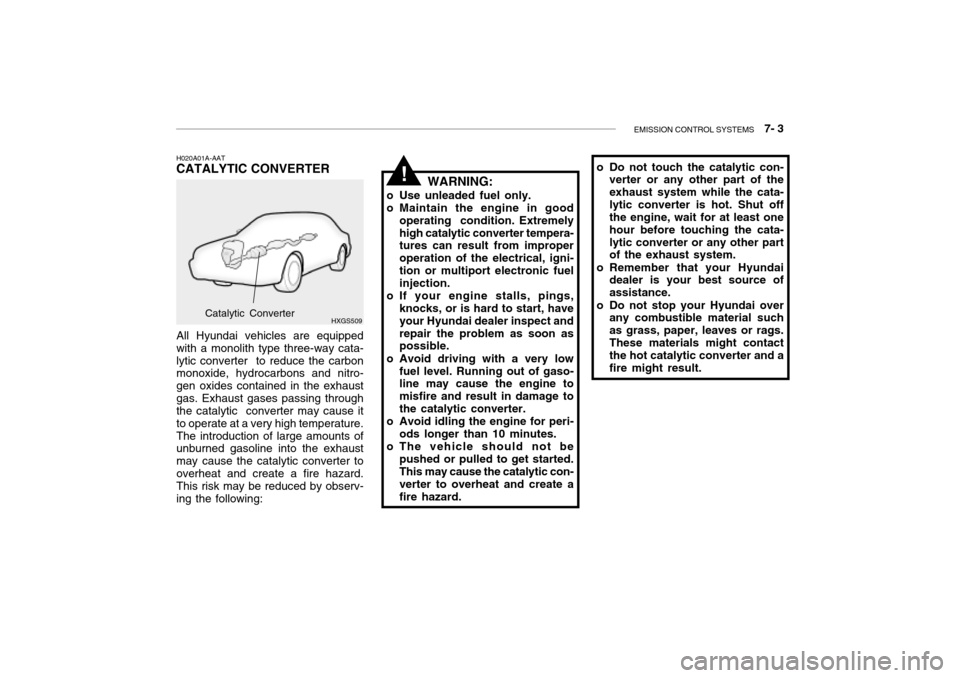
CATALYTIC CONVERTER
HXGS509
All Hyundai vehicles are equippedwith a monolith type three-way cata-lytic converter to reduce the carbon monoxide, hydrocarbons and nitro- gen oxides contained in the exhaustgas. Exhaust gases passing through the catalytic converter may cause it to operate at a very high temperature.The introduction of large amounts of unburned gasoline into the exhaust may cause the catalytic converter tooverheat and create a fire hazard. This risk may be reduced by observ- ing the following:
Catalytic Converter o Do not touch the catalytic con-
verter or any other part of the exhaust system while the cata-lytic converter is hot. Shut off the engine, wait for at least one hour before touching the cata-lytic converter or any other part of the exhaust system.
o Remember that your Hyundai dealer is your best source of assistance.
o Do not stop your Hyundai over any combustible material suchas grass, paper, leaves or rags.These materials might contact the hot catalytic converter and a fire might result.
!
Page 222 of 230

9- 2 VEHICLE SPECIFICATIONS
3.0 V6
J010A02L-GAT MEASUREMENT
4,875 (191.8) 1,800 (70.86)
1,420 (55.9)
2,750 (108.2) 1,540 (60.6)
1,530 (60.23)
Overall lengthOverall widthOverall height Wheel base Wheel tread
Front
Rear
Type Wheel free play Rack strokeOil pump type Rack and pinion0 ~ 30 mm (0 ~ 1.18 in.) 146 mm (5.74 in.) Vane type
J060A01L-GAT FUEL SYSTEM
J020A01L-GAT POWER STEERING
Fuel tank capacity 70 liter J030A03L-GAT TIRE
205/65 R15 94V 205/60 R16 96V
StandardOption
J050A01L-GAT BRAKE
Dual hydraulic with brake booster Ventilated discSolid disc Cable operated on rear wheel
Type Front brake typeRear brake type Parking brake
Item Battery
Alternator 120A (13.5V)
2.5 V6
110A (13.5V)
J040A02L-GAT ELECTRICAL
MF 68AH (MF)
3.5 V6
mm (in.)
Page 223 of 230

VEHICLE SPECIFICATIONS 9- 3
1 - 2 - 3 - 4 - 5 - 6
Auto lash Auto lash
1.0 ~ 1.1 mm 0.7 ~ 0.8 mm 700 ± 100
SH, SG or SG/CD ABOVE multigrade and fuel-efficient oil
3.5 V6
6-Cyl. V-type, DOHC 93 x 85.8
3,497
BTDC 5 2
J070A02L-GAT ENGINE
ITEMS
Bore x Stroke Displacement (cc) Firing order
Valve clearance Intake
(warm engine) Exhaust Spark plug gap Unleaded
Leaded
Idle speed (rpm)Ignition timing Oil grade (API) 3.0 V6
6-Cyl. V-type, DOHC 91.1 x 76
2,972
BTDC 5 22.5 V6
6-Cyl. V-type, DOHC 84 x 75.02,493
BTDC 12 10