2002 Hyundai Grandeur engine coolant
[x] Cancel search: engine coolantPage 201 of 230

6- 24 DO-IT-YOURSELF MAINTENANCE
G240A01A-AAT
POWER STEERING HOSES
It is suggested that you check the
power steering hose connections for fluid leakage at regular intervals.
The power steering hoses should be
replaced if there is severe surface cracking, scuffing or worn spots. De- terioration of the hose could causepremature failure.
G230A03A-GAT
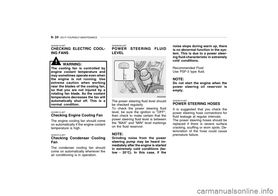
POWER STEERING FLUID LEVEL
HXG2006
The power steering fluid level should
be checked regularly.
To check the power steering fluid
level, be sure the ignition is "OFF", then check to make certain that the power steering fluid level is betweenthe "MAX" and "MIN" level markings on the fluid reservoir.
NOTE: Grinding noise from the power
steering pump may be heard im- mediately after the engine is started in extremely cold conditions (be- low - 20°C). In this case, if the noise stops during warm up, there is no abnormal function in the sys- tem. This is due to a power steer-ing fluid characteristic in extremely cold conditions. Recommended Fluid Use PSF-3 type fluid. NOTE: Do not start the engine when the power steering oil reservoir is empty.
G220A01A-AAT
CHECKING ELECTRIC COOL- ING FANS
WARNING:
The cooling fan is controlled by
engine coolant temperature and may sometimes operate even whenthe engine is not running. Use extreme caution when working near the blades of the cooling fan,so that you are not injured by a rotating fan blade. As the coolant temperature decreases the fan willautomatically shut off. This is a normal condition.
G220B01A-AAT
Checking Engine Cooling Fan
The engine cooling fan should come
on automatically if the engine coolanttemperature is high.
G220C01A-AAT
Checking Condenser Cooling Fan
The condenser cooling fan should
come on automatically whenever the air conditioning is in operation.
!
Page 202 of 230

DO-IT-YOURSELF MAINTENANCE 6- 25
G290A02L-GAT
HEADLIGHT AIMING ADJUST- MENT
HID Type (If installed)
WARNING:
If you need headlight aiming ad- justment, have your vehicle in- spected by your Hyundai Dealer. Don't attempt to replace or inspect the HID headlight bulb to prevent danger of an electric shock.
Vertical Aiming HorizontalAiming
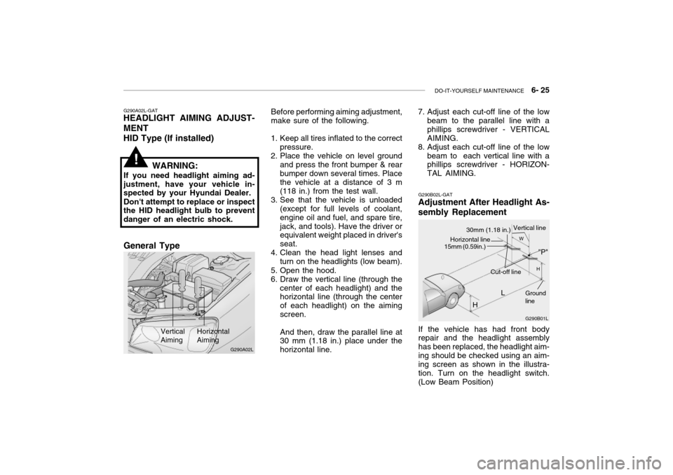
Before performing aiming adjustment, make sure of the following.
1. Keep all tires inflated to the correct pressure.
2. Place the vehicle on level ground
and press the front bumper & rear bumper down several times. Place the vehicle at a distance of 3 m (118 in.) from the test wall.
3. See that the vehicle is unloaded (except for full levels of coolant,engine oil and fuel, and spare tire,jack, and tools). Have the driver or equivalent weight placed in driver's seat.
4. Clean the head light lenses and
turn on the headlights (low beam).
5. Open the hood.
6. Draw the vertical line (through the center of each headlight) and the horizontal line (through the center of each headlight) on the aimingscreen. And then, draw the parallel line at 30 mm (1.18 in.) place under the horizontal line.
!
G290B02L-GAT
Adjustment After Headlight As- sembly Replacement
G290B01L
LW
H
H Cut-off line
Ground line
If the vehicle has had front body repair and the headlight assembly has been replaced, the headlight aim-ing should be checked using an aim- ing screen as shown in the illustra- tion. Turn on the headlight switch.(Low Beam Position)
"P"
Horizontal line15mm (0.59in.)
30mm (1.18 in.) Vertical line
7. Adjust each cut-off line of the low
beam to the parallel line with a phillips screwdriver - VERTICALAIMING.
8. Adjust each cut-off line of the low
beam to each vertical line with a phillips screwdriver - HORIZON- TAL AIMING.
G290A02L
General Type
Page 214 of 230

7- 2 EMISSION CONTROL SYSTEMS
H010A01A-GAT
EMISSION CONTROL SYSTEM (If Installed)
Your Hyundai is equipped with an
emission control system to meet all requirements of the Emission prohibi-tion rules of your province.
There are three emission control sys-
tems which are as follows.
1) Crankcase emission control sys-
tem
2) Evaporative emission control sys-
tem
3) Exhaust emission control system
In order to assure the proper function
of the emission control systems, it is recommended that you have your car inspected and maintained by an au-thorized Hyundai dealer in accordance with the maintenance schedule in this manual. H010B01A-AAT
1. Crankcase Emission Control
System
The positive crankcase ventilation
system is employed to prevent airpollution caused by blow-by gasesbeing emitted from the crankcase. This system supplies fresh air to the crankcase through the air intake hose.Inside the crankcase, the fresh air mixes with blow-by gases, which then pass through the PCV valve and intothe induction system.
H010C02Y-GAT
2. Evaporative Emission
Control System
The Evaporative Emission Control
System is designed to prevent fuel vapors from escaping into the atmo- sphere. Canister
While the engine is inoperative, fuel
vapors generated inside the fuel tank are absorbed and stored in the canis- ter. When the engine is running, the fuel vapors absorbed in the canisterare drawn into the induction system through the purge control solenoidvalve. Purge Control Solenoid Valve
The purge control solenoid valve is
controlled by the ECM; when the en- gine coolant temperature is low, and during idling, it closes, so that evapo- rated fuel is not taken into the surgetank. After engine warm-up, during ordinary driving, it opens so as to introduce evaporated fuel to the surgetank.
H010D01A-AAT
3. Exhaust Emission Control
System
The exhaust emission control system
is a highly effective system whichcontrols exhaust emission while main- taining good vehicle performance.
H010E01Y-GAT
EGR System
This system helps control nitrogen
oxides by recirculating a part of the exhaust gas into the engine, therebyreducing cylinder combustion tem- perature.
Page 224 of 230

9- 4 VEHICLE SPECIFICATIONS
Oil & Grease Standard
API SH or SAE 20W-40, 20W-50 (ABOVE -10 C)
SG ABOVE SAE 15W-40, 15W-50 (ABOVE -15 C) SAE 10W-30 (-25 C ~ 40 C) SAE 10W-40, 10W-50 (ABOVE -25 C) SAE 5W-20 *1, *2 (BELOW -10 C) SAE 5W-30 *1 (BELOW 10 C)SAE 5W-40 *1 (BELOW 20 C)
*1. Restricted to driving condition and dealing area *2. Not recommended for sustained high speed vehicle operation Normal driving conditionSevere driving condition HYUNDAI GENUINE PARTS MTF 75W/90 (API GL-4) DIAMOND ATF SP-III, SK ATF SP-IIIEthylene glycol, base for aluminum PSF-3 DOT 3, DOT 4 or Equivalent
J080A03L-GAT LUBRICATION CHART
Item
Engine Oil Engine oil consumption
Transaxle Manual Auto
Coolant Power steering gear Brakes and clutch fluidQ'ty (liter)
Drain and refill (With oil filter) 3.5 L / 3.0 L : 4.3 2.5 L : 4.5 MAX. 1L / 1500 Km MAX. 1L / 1000 Km 2.1 7.8 (2.5L), 8.5 (3.0L / 3.5L)9.5 (2.5L), 11.2 (3.0L / 3.5L) 1.0 As required
Page 227 of 230

INDEX 10- 3
D Defrosting / Defogging .............................................. 1-81
Door Door locks ................................................................ 1-6
Door courtesy light ................................................. 1-70
Locking and unlocking front doors with a key ......... 1-6
Drink Holder .............................................................. 1-56
Drive Belts ...................................................... 6-18, 6-21
Driving
Economical driving ..................................... 2-14 ~ 2-15
Smooth cornering ................................................... 2-15
Winter driving ......................................................... 2-15
E Emission Control System ................................. 7-1 ~ 7-3
Engine Before starting the engine ....................................... 2-3
Compartment ................................................... 6-1~6-3 Coolant ......................................................... 6-8 ~ 6-10
Coolant temperature gauge ................................... 1-45
If the engine overheats ............................................ 3-4
Number .................................................................... 8-2
Oil ............................................................................. 6-6
Starting ..................................................................... 2-4
Engine Exhaust Can Be Dangerous ........................... 2-2F Fan Speed Control
.................................................... 1-77
Fog Light Front ....................................................................... 1-47
Rear ........................................................... 1-47 ~ 1-48
Front Seats Adjustable front seats ............................................ 1-11
Adjustable headrests .................................. 1-12 ~ 1-13
Adjusting seat forward and rearward ......... 1-11 ~ 1-12 Adjusting seatback angle ....................................... 1-12
Lumbar support control .......................................... 1-13 Seat cushion height adjustment............................ 1-13
Seat warmer ........................................................... 1-17
Fuel Capacity ................................................................... 9-2
Gauge .................................................................... 1-45
recommendations ..................................................... 1-2
Fuel Filler Lid Remote release ...................................................... 1-67
Manual ................................................................... 1-67
Fuses ............................................................ 6-21 ~ 6-23 G General Checks .......................................................... 6-5
Glove Box ................................................................. 1-61