2002 Hyundai Grandeur instrument panel
[x] Cancel search: instrument panelPage 51 of 230
1- 38 FEATURES OF YOUR HYUNDAI
o Modification to SRS components
or wiring, including the addition of any kind of badges to the pad covers or modifications to the body structure, can adverselyaffect SRS performance and leadto possible injury.
o For cleaning the airbag pad cov- ers, use only a soft, dry cloth or one which has been moistened with plain water. Solvents orcleaners could adversely affectthe airbag covers and properdeployment of the system.
o No objects should be placed over
or near the airbag modules onthe steering wheel, instrumentpanel, and the front passenger'spanel above the glove box, be-cause any such object could cause harm if the vehicle is in a crash severe enough to causethe airbags to inflate.
o If the airbags inflate, they must be replaced by an authorizedHyundai dealer. o Do not tamper with or discon-
nect SRS wiring, or other com-ponents of the SRS system. Do- ing so could result in injury, due to accidental firing of the airbagsor by rendering the SRS inopera-tive.
o If components of the airbag sys- tem must be discarded, or if the vehicle must be scrapped, cer- tain safety precautions must beobserved. Your Hyundai dealerknows these precautions and cangive you the necessary informa- tion. Failure to follow these pre- cautions and procedures couldincrease the risk of personal in-jury.
o If you sell your vehicle, make certain that this manual is trans- ferred to the new owner.
o If your car was flooded and has
soaked carpeting or water on flooring, you shouldn't try to startengine; have the car towed toauthorized Hyundai dealer.
B240C02L
WARNING:
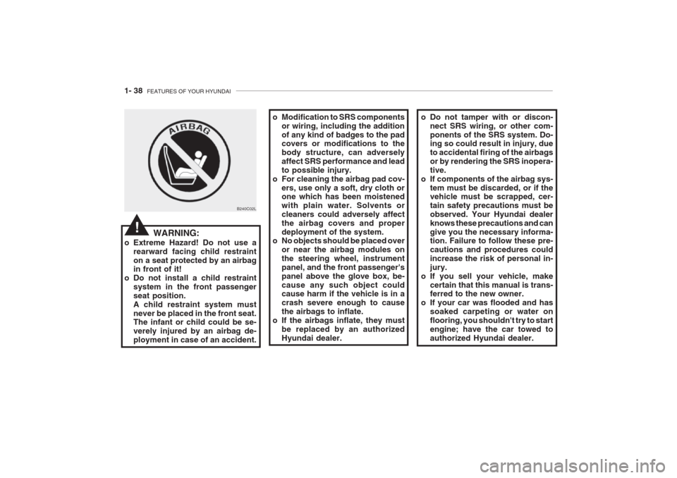
o Extreme Hazard! Do not use a rearward facing child restraint on a seat protected by an airbag in front of it!
o Do not install a child restraint system in the front passenger seat position.A child restraint system mustnever be placed in the front seat. The infant or child could be se- verely injured by an airbag de-ployment in case of an accident.
!
Page 61 of 230
1- 48 FEATURES OF YOUR HYUNDAI
To turn on the rear fog lights, push the switch. They will come on when theheadlight switch is in the second posi-tion and the key is in the "ON" position.
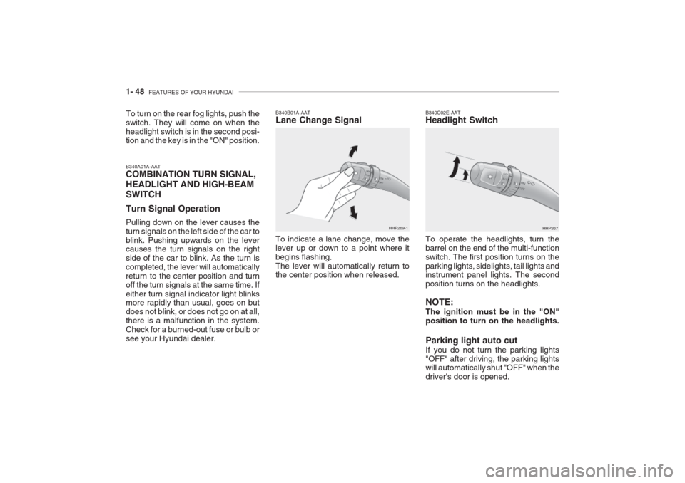
B340A01A-AAT COMBINATION TURN SIGNAL, HEADLIGHT AND HIGH-BEAMSWITCH Turn Signal Operation Pulling down on the lever causes the turn signals on the left side of the car toblink. Pushing upwards on the lever causes the turn signals on the right side of the car to blink. As the turn iscompleted, the lever will automaticallyreturn to the center position and turnoff the turn signals at the same time. Ifeither turn signal indicator light blinks more rapidly than usual, goes on but does not blink, or does not go on at all,there is a malfunction in the system.Check for a burned-out fuse or bulb orsee your Hyundai dealer. B340B01A-AAT Lane Change Signal To indicate a lane change, move the lever up or down to a point where itbegins flashing.The lever will automatically return to the center position when released.
HHP269-1
B340C02E-AAT Headlight Switch To operate the headlights, turn the barrel on the end of the multi-functionswitch. The first position turns on the
parking lights, sidelights, tail lights and instrument panel lights. The second position turns on the headlights. NOTE: The ignition must be in the "ON" position to turn on the headlights. Parking light auto cut If you do not turn the parking lights "OFF" after driving, the parking lights will automatically shut "OFF" when the driver's door is opened. HHP267
Page 68 of 230
FEATURES OF YOUR HYUNDAI 1- 55
NOTE:
o When refueling a vehicle that is
not parked on level ground or taking away the battery, the TripComputer can recognize thewrong amount of fuel.
o The trip Computer can recognize the amount of fuel more thanactual amount if there is leakageof fuel, because it can recognizeonly the normal consumption offuel.
o When refueling with more than 7 liters at least, the Trip Computerwill recognize refueling.
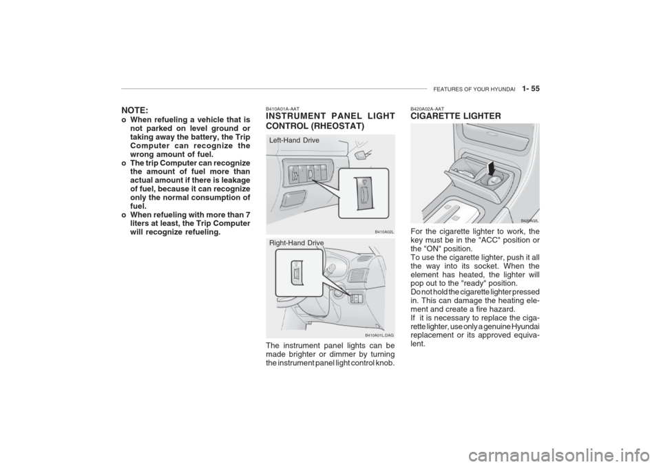
The instrument panel lights can be made brighter or dimmer by turningthe instrument panel light control knob.Right-Hand Drive
B410A01L.DAG
B410A01A-AAT INSTRUMENT PANEL LIGHT CONTROL (RHEOSTAT)Left-Hand Drive
B410A02L B420A02L
For the cigarette lighter to work, the key must be in the "ACC" position orthe "ON" position.To use the cigarette lighter, push it allthe way into its socket. When theelement has heated, the lighter will pop out to the "ready" position. Do not hold the cigarette lighter pressedin. This can damage the heating ele-ment and create a fire hazard.If it is necessary to replace the ciga-rette lighter, use only a genuine Hyundai replacement or its approved equiva- lent.
B420A02A-AAT CIGARETTE LIGHTER
Page 98 of 230

FEATURES OF YOUR HYUNDAI 1- 85
2. Push the "TEMP" button to set the
desired temperature. The temperature will increase to themaximum 32 C(90 F) by pushingon the button. Each push of the button will cause the temperature to increase by 0.5 C(1 F).The temperature will decrease tothe minimum 17 C(62 F) by push-ing on the button. Each push ofthe button will cause the tempera- ture to decrease by 0.5 °C(1 F).
NOTE: If the battery has been discharged or disconnected, the temperaturemode will reset to centigrade de-gree.
The FATC (Full Automatic Tempera- ture Control) system automaticallycontrols the heating and cooling bydoing as follows:
1. Push the "AUTO" switch. The indi- cator light will illuminate confirming that the Face, Floor and/or Bi-Levelmodes as well as the blower speedand, air conditioner will be controlled automatically. Photo sensor
B970C01L
B970C03Y-GAT Automatic Operation
NOTE: Never place things on the sensor which is located in the car on theinstrument panel to ensure bettercontrol of the heating and coolingsystem.
B970C02L
B970C03L
This is a normal condition and youcan adjust the temperature modefrom centigrade to farenheit as fol-lows;Press the TEMP button down 3 sec- onds or more with the AMB button held down. The display shows thatthe unit of temperature is adjustedto contigrade or fahrenheit.( C
� �
� �
� F or F
� �
� �
� C)
Page 199 of 230
6- 22 DO-IT-YOURSELF MAINTENANCE
strument panel junction box you will find a list showing the circuits pro- tected by each fuse.
If any of your car's lights or other
electrical accessories stop working, ablown fuse could be the reason. If the fuse has burned out, you will see that the metal strip inside the fuse hasburned through. If you suspect a blown fuse, follow this procedure:
1. Turn off the ignition and all other switches.
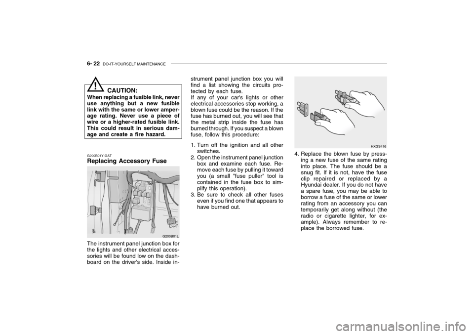
2. Open the instrument panel junction box and examine each fuse. Re- move each fuse by pulling it toward you (a small "fuse puller" tool iscontained in the fuse box to sim- plify this operation).
3. Be sure to check all other fuses even if you find one that appears to have burned out.
HXGS416
4. Replace the blown fuse by press- ing a new fuse of the same rating into place. The fuse should be a snug fit. If it is not, have the fuseclip repaired or replaced by a Hyundai dealer. If you do not have a spare fuse, you may be able toborrow a fuse of the same or lower rating from an accessory you can temporarily get along without (theradio or cigarette lighter, for ex- ample). Always remember to re- place the borrowed fuse.
G200B01Y-GAT Replacing Accessory Fuse
G200B01L
The instrument panel junction box for the lights and other electrical acces-sories will be found low on the dash- board on the driver's side. Inside in- CAUTION:
When replacing a fusible link, never
use anything but a new fusible link with the same or lower amper- age rating. Never use a piece of wire or a higher-rated fusible link.This could result in serious dam- age and create a fire hazard.
!
Page 212 of 230

DO-IT-YOURSELF MAINTENANCE 6- 35
FUSE RATING
25A 20A10A15A10A10A10A15A10A10A15A 10A 10A 10A20A10A 15A 10A15A10A10A15A10A20A 10A 10A 10A 10A10A10A 10A 10A PROTECTED COMPONENTS
Power seat
Seat warmerEPS controls
ETS relay
(HID) Head lights, DRL controls, AQS sensor
Blower & A/C controls
Turn & Hazard controlsNot used
Cruise switch, Instrument cluster
Head light leveling switch, Rain sensor, IMS controls
Rain sensor relay, Wiper & Washer controls
Home link connector, Left (Right) vanity lights, Sunroof, Blower & A/C controls,Electronic chrome mirrorNot used
Audio
Front (Rear) cigarette lighter, Accessory socket
IMS controls, Driver door module, RheostatNot used
Rear for light relay
Stop lights, Left (Right) personal lights, Left (Right) rear door lights
Door warning & Ignition key illumination, Courtesy lightsInstrument clusterSRS controls
Automatic transaxle controls, Back-up light switch, Vehicle speed sensor
Fuel filler door & Trunk lid opener, Driver (Assister) door module
Multipurpose check connector, Audio, lmmobiilizer controls, Trip computers, Digital
clock, Blower & A/C controls, Instrument cluster
Left (Right) inside lights, (HID) Head lights, Fog light relay, Right HID turn signal light,Right rear combination light
Stop light failure relay
Immobilizer controls, TCS switch, Trip computers, Instrument cluster
ETACM, Hazard switch, Auto light sensor
Antenna, Blower & A/C controls, Left (Right) outside mirror motor & Folding motor
(HID) Head lights, Front (Rear) cigarette lighters, Left (Right) license lights, Left HID
Turn signal light, Left rear combination lightBurglar alarm relay, Transaxle range switch, Start relay, ETS controlsDESCRIPTION P/SEAT
S/HTR EPSETS
H/LP
A/CON SW HAZARDSPARE
CRUISE IMS
WIPER
ETACS
SPARE AUDIO
C/LIGHTER MIRRORSPARE
RR FOG
STOP LP
ROOM LP
A/BAG IND A/BAGB/UP
T/LID
D/CLOCK
RH TAILSPARE
CLUSTER T/SIG
RR HTD IND
LH TAIL
START
G200D01L-GAT
Instrument Panel Junction Box
G200D01L
Page 228 of 230
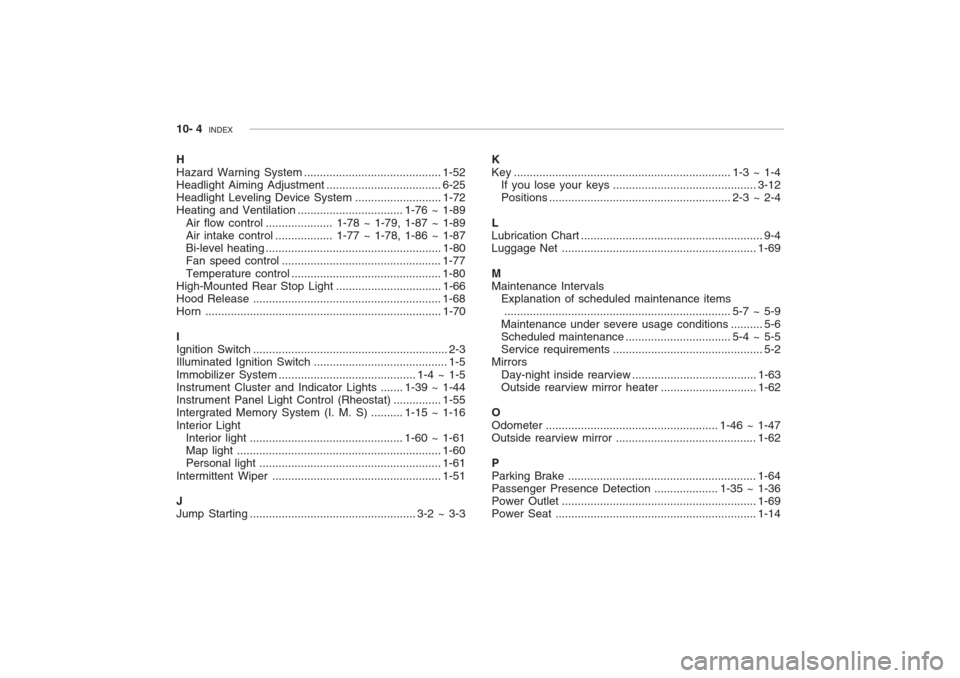
10- 4 INDEX
H Hazard Warning System........................................... 1-52
Headlight Aiming Adjustment .................................... 6-25
Headlight Leveling Device Syst em ...........................1-72
Heating and Ventilation ................................. 1-76 ~ 1-89
Air flow control ..................... 1-78 ~ 1-79, 1-87 ~ 1-89
Air intake control .................. 1-77 ~ 1-78, 1-86 ~ 1-87
Bi-level heating ....................................................... 1-80
Fan speed control .................................................. 1-77
Temperature control ............................................... 1-80
High-Mounted Rear Stop L ight .................................1-66
Hood Release ........................................................... 1-68
Horn .......................................................................... 1-70
I Ignition Switch ............................................................. 2-3
Illuminated Ignition Switch .......................................... 1-5 Immobilizer Sy stem ........................................... 1-4 ~ 1-5
Instrument Cluster and Indicator Lights ....... 1-39 ~ 1-44
Instrument Panel Light Control (Rheost at) ............... 1-55
Intergrated Memory System (I. M. S) .......... 1-15 ~ 1-16 Interior Light Interior light ................................................ 1-60 ~ 1-61
Map light ................................................................ 1-60
Personal light ......................................................... 1-61
Intermittent Wiper ..................................................... 1-51
J Jump Starting .................................................... 3-2 ~ 3-3 K
Key .................................................................... 1-3 ~ 1-4
If you lose your keys ............................................. 3-12
Positions ......................................................... 2-3 ~ 2-4
L Lubrication Chart ......................................................... 9-4
Luggage Net ............................................................. 1-69
MMaintenance Intervals Explanation of scheduled maintenance items....................................................................... 5-7 ~ 5-9
Maintenance under severe usage cond itions .......... 5-6
Scheduled maintenance ................................. 5-4 ~ 5-5
Service requ irements............................................... 5-2
Mirrors
Day-night inside rearview ....................................... 1-63
Outside rearview mirror heat er ..............................1-62
O
Odometer ...................................................... 1-46 ~ 1-47 Outside rearview mirror ............................................ 1-62
P Parking Brake ........................................................... 1-64
Passenger Presence Detec tion .................... 1-35 ~ 1-36
Power Outle t ............................................................. 1-69
Power Seat ............................................................... 1-14