2002 Hyundai Atos clock
[x] Cancel search: clockPage 183 of 249
FEATURES OF YOUR HYUNDAI
1-46 B922B02X-GAT
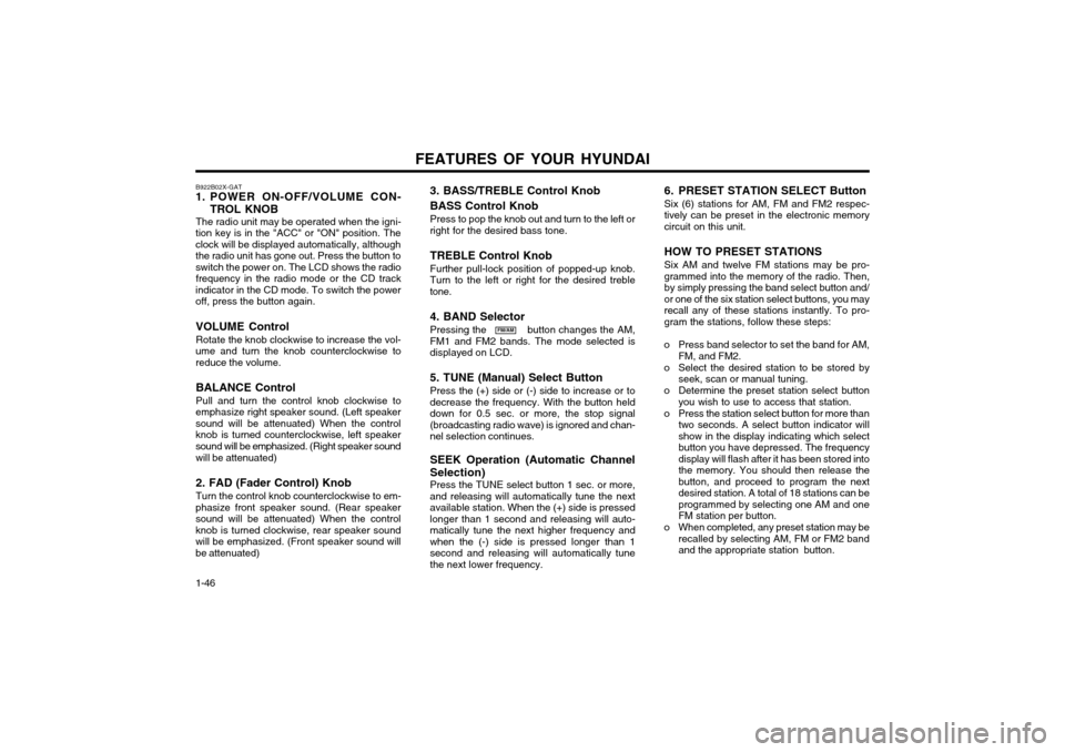
1. POWER ON-OFF/VOLUME CON-
TROL KNOB
The radio unit may be operated when the igni-
tion key is in the "ACC" or "ON" position. The clock will be displayed automatically, althoughthe radio unit has gone out. Press the button toswitch the power on. The LCD shows the radio frequency in the radio mode or the CD track
indicator in the CD mode. To switch the poweroff, press the button again.
VOLUME Control Rotate the knob clockwise to increase the vol-
ume and turn the knob counterclockwise to reduce the volume.
BALANCE Control Pull and turn the control knob clockwise to
emphasize right speaker sound. (Left speaker sound will be attenuated) When the controlknob is turned counterclockwise, left speakersound will be emphasized. (Right speaker sound
will be attenuated) 2. FAD (Fader Control) Knob Turn the control knob counterclockwise to em-
phasize front speaker sound. (Rear speaker sound will be attenuated) When the controlknob is turned clockwise, rear speaker soundwill be emphasized. (Front speaker sound willbe attenuated)
FM/AM 6. PRESET STATION SELECT Button Six (6) stations for AM, FM and FM2 respec- tively can be preset in the electronic memorycircuit on this unit. HOW TO PRESET STATIONS Six AM and twelve FM stations may be pro- grammed into the memory of the radio. Then,by simply pressing the band select button and/or one of the six station select buttons, you mayrecall any of these stations instantly. To pro-gram the stations, follow these steps:
o Press band selector to set the band for AM, FM, and FM2.
o Select the desired station to be stored by seek, scan or manual tuning.
o Determine the preset station select button you wish to use to access that station.
o Press the station select button for more than two seconds. A select button indicator willshow in the display indicating which selectbutton you have depressed. The frequencydisplay will flash after it has been stored intothe memory. You should then release thebutton, and proceed to program the nextdesired station. A total of 18 stations can beprogrammed by selecting one AM and oneFM station per button.
o When completed, any preset station may be recalled by selecting AM, FM or FM2 bandand the appropriate station button.
3. BASS/TREBLE Control Knob BASS Control Knob Press to pop the knob out and turn to the left or right for the desired bass tone. TREBLE Control Knob Further pull-lock position of popped-up knob. Turn to the left or right for the desired trebletone. 4. BAND Selector Pressing the button changes the AM, FM1 and FM2 bands. The mode selected isdisplayed on LCD. 5. TUNE (Manual) Select Button Press the (+) side or (-) side to increase or to decrease the frequency. With the button helddown for 0.5 sec. or more, the stop signal(broadcasting radio wave) is ignored and chan-nel selection continues. SEEK Operation (Automatic Channel Selection) Press the TUNE select button 1 sec. or more, and releasing will automatically tune the nextavailable station. When the (+) side is pressedlonger than 1 second and releasing will auto-matically tune the next higher frequency andwhen the (-) side is pressed longer than 1second and releasing will automatically tunethe next lower frequency.
Page 193 of 249
DRIVING YOUR HYUNDAI
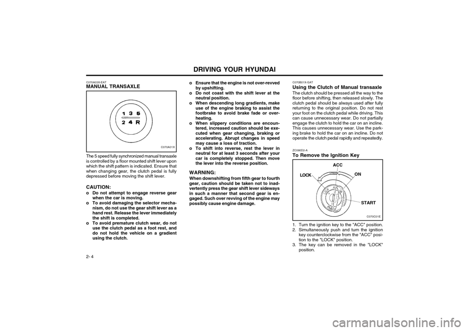
2- 4 1. Turn the ignition key to the "ACC" position.
2. Simultaneously push and turn the ignition
key counterclockwise from the "ACC" posi- tion to the "LOCK" position.
3. The key can be removed in the "LOCK" position.
C070B01X-GAT
Using the Clutch of Manual transaxle
The clutch should be pressed all the way to thefloor before shifting, then released slowly. Theclutch pedal should be always used after fullyreturning to the original position. Do not restyour foot on the clutch pedal while driving. Thiscan cause unnecessary wear. Do not partiallyengage the clutch to hold the car on an incline.This causes unnecessary wear. Use the park-
ing brake to hold the car on an incline. Do not
operate the clutch pedal rapidly and repeatedly. ZC090D2-A
To Remove the Ignition Key
C070A03X-EAT
MANUAL TRANSAXLE
C070A01X
The 5 speed fully synchronized manual transaxle
is controlled by a floor mounted shift lever upon which the shift pattern is indicated. Ensure thatwhen changing gear, the clutch pedal is fullydepressed before moving the shift lever. CAUTION:
o Do not attempt to engage reverse gear when the car is moving.
o To avoid damaging the selector mecha- nism, do not use the gear shift lever as a hand rest. Release the lever immediatelythe shift is completed.
o To avoid premature clutch wear, do not use the clutch pedal as a foot rest, anddo not hold the vehicle on a gradientusing the clutch. o Ensure that the engine is not over-revved
by upshifting.
o Do not coast with the shift lever at the neutral position.
o When descending long gradients, make use of the engine braking to assist thefootbrake to avoid brake fade or over-heating.
o When slippery conditions are encoun- tered, increased caution should be exe-cuted when gear changing, braking oraccelerating. Abrupt changes in speedmay cause a loss of traction.
o To shift into reverse, rest the lever in neutral for at least 3 seconds after yourcar is completely stopped. Then movethe lever into the reverse position.
WARNING: When downshifting from fifth gear to fourth
gear, caution should be taken not to inad-vertently press the gear shift lever sidewaysin such a manner that second gear is en-gaged. Such over revving of the engine maypossibly cause engine damage.
C070C01E
LOCK
ACC
ON
START
Page 205 of 249
WHAT TO DO IN AN EMERGENCY
3-4 SD070B1-E
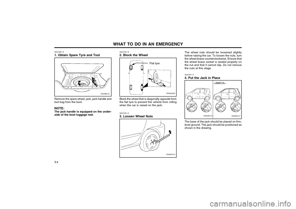
1. Obtain Spare Tyre and Tool
Remove the spare wheel, jack, jack handle and
tool bag from the boot.
NOTE: The jack handle is equipped on the under-
side of the boot luggage mat.
SSA3050D
Flat tyre
SD070D1-E
2. Block the Wheel
Block the wheel that is diagonally opposite from the flat tyre to prevent the vehicle from rollingwhen the car is raised on the jack.
D060D01A
SD070E1-E
3. Loosen Wheel Nuts The wheel nuts should be loosened slightly before raising the car. To loosen the nuts, turnthe wheel brace counterclockwise. Ensure thatthe wheel brace socket is seated properly onthe nut and that it cannot slip. Do not removethe nuts at this stage. SD070F1-F
4. Put the Jack in Place
The base of the jack should be placed on firm, level ground. The jack should be positioned asshown in the drawing.D060E01A
D040B01X
Page 206 of 249
3-5
WHAT TO DO IN AN EMERGENCY
SD070G1-E
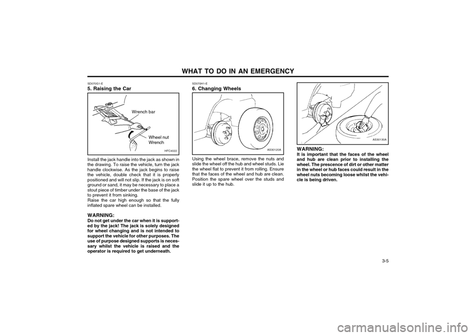
5. Raising the Car
AS30120A
SD070H1-E 6. Changing Wheels
Using the wheel brace, remove the nuts and
slide the wheel off the hub and wheel studs. Lie the wheel flat to prevent it from rolling. Ensurethat the faces of the wheel and hub are clean.Position the spare wheel over the studs andslide it up to the hub.
Install the jack handle into the jack as shown in
the drawing. To raise the vehicle, turn the jackhandle clockwise. As the jack begins to raisethe vehicle, double check that it is properlypositioned and will not slip. If the jack is on softground or sand, it may be necessary to place astout piece of timber under the base of the jackto prevent it from sinking.
Raise the car high enough so that the fully
inflated spare wheel can be installed.
WARNING: Do not get under the car when it is support-
ed by the jack! The jack is solely designed for wheel changing and is not intended tosupport the vehicle for other purposes. Theuse of purpose designed supports is neces-sary whilst the vehicle is raised and theoperator is required to get underneath. WARNING: It is important that the faces of the wheel
and hub are clean prior to installing the wheel. The prescence of dirt or other matterin the wheel or hub faces could result in thewheel nuts becoming loose whilst the vehi-cle is being driven.
AS30130A
HFC4022
Wrench bar
Wheel nut Wrench
Page 207 of 249
WHAT TO DO IN AN EMERGENCY
3-6 SD070I1-E
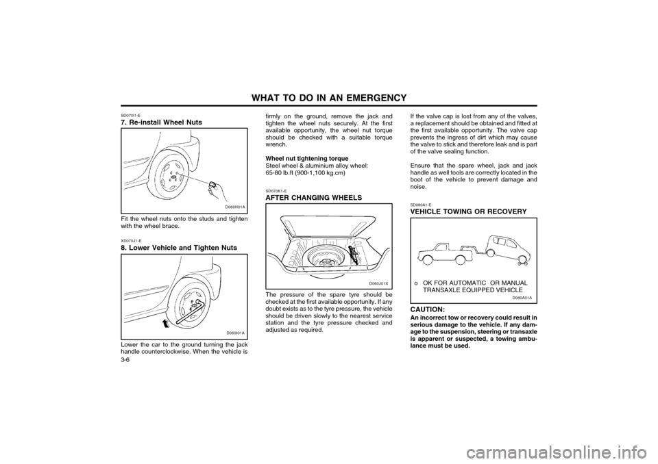
7. Re-install Wheel Nuts
D060H01A
Fit the wheel nuts onto the studs and tighten
with the wheel brace.
D060I01A
XD070J1-E
8. Lower Vehicle and Tighten Nuts
Lower the car to the ground turning the jack
handle counterclockwise. When the vehicle is firmly on the ground, remove the jack and tighten the wheel nuts securely. At the firstavailable opportunity, the wheel nut torqueshould be checked with a suitable torquewrench. Wheel nut tightening torque Steel wheel & aluminium alloy wheel:65-80 lb.ft (900-1,100 kg.cm) SD070K1-E
AFTER CHANGING WHEELS
The pressure of the spare tyre should be
checked at the first available opportunity. If any doubt exists as to the tyre pressure, the vehicleshould be driven slowly to the nearest servicestation and the tyre pressure checked andadjusted as required. If the valve cap is lost from any of the valves,a replacement should be obtained and fitted atthe first available opportunity. The valve capprevents the ingress of dirt which may causethe valve to stick and therefore leak and is partof the valve sealing function. Ensure that the spare wheel, jack and jack handle as well tools are correctly located in theboot of the vehicle to prevent damage andnoise.
D080A01A
o OK FOR AUTOMATIC OR MANUAL
TRANSAXLE EQUIPPED VEHICLE
SD080A1-E
VEHICLE TOWING OR RECOVERY CAUTION:
An incorrect tow or recovery could result in serious damage to the vehicle. If any dam-age to the suspension, steering or transaxleis apparent or suspected, a towing ambu-lance must be used.D060J01X
Page 221 of 249
DO-IT-YOURSELF MAINTENANCE 6-3
AS60050A
FL
ZG030C1-A
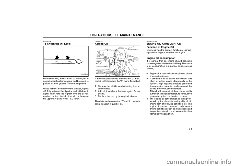
To Check the Oil Level
Before checking the oil, warm up the engine to
normal operating temperature and be sure it is parked on level ground. Turn the engine off.
Wait a minute, then remove the dipstick, wipe it
off, fully reinsert the dipstick and withdraw itagain. Then note the highest level the oil hasreached on the dipstick. It should be betweenthe upper ("F") and lower ("L") range. ZG030D1-A
Adding Oil
G030D01A
If the oil level is close to or below the "L" mark,
add oil until it reaches the "F" mark. To add oil:
1. Remove the oil filler cap by turning it coun- terclockwise.
2. Add oil, then check the level again. Do not overfill.
3. Replace the cap by turning it clockwise.
The distance between the "F" and "L" marks is
equal to about 1 quart of oil. G350A01A-GAT
ENGINE OIL CONSUMPTION Function of Engine Oil
Engine oil has the primary function of lubricat-
ing and cooling the inside of the engine. Engine oil consumption
If is normal that an engine should consume
some engine oil while normal driving. The cause of oil consumption in a normal engine are asfollows;
o Engine oil is used to lubricate pistons, piston rings and cylinders.
o A thin film of oil is left on the cylinder wall when a piston moves downwards in the cylinder. High negative pressure generatedduring engine operation sucks some of theoil into the combustion chamber. This oil with some oil of the cylinder wall is burned by the high temperature combustiongases during the combustion process.
o The engine oil consumption is strongly ef- fected by the viscosity and quality of oil,engine rpm and driving condition etc. The
engine oil is more consumed under severedriving conditions such as high speeds and
frequent acceleration and deceleration thannormal driving condition.
Page 222 of 249
DO-IT-YOURSELF MAINTENANCE
6-4 G040A01X-GAT
CHANGING THE OIL AND FILTER
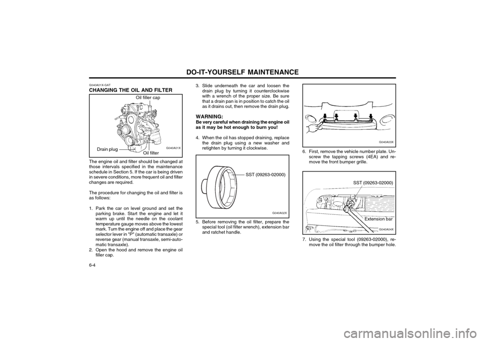
Oil filler cap
Oil filter G040A01X
Drain plug
The engine oil and filter should be changed at
those intervals specified in the maintenance schedule in Section 5. If the car is being driven in severe conditions, more frequent oil and filter
changes are required.
The procedure for changing the oil and filter is
as follows:
1. Park the car on level ground and set the parking brake. Start the engine and let it warm up until the needle on the coolanttemperature gauge moves above the lowest
mark. Turn the engine off and place the gearselector lever in "P" (automatic transaxle) orreverse gear (manual transaxle, semi-auto-matic transaxle).
2. Open the hood and remove the engine oil filler cap. 3. Slide underneath the car and loosen the
drain plug by turning it counterclockwisewith a wrench of the proper size. Be sure
that a drain pan is in position to catch the oilas it drains out, then remove the drain plug.
WARNING: Be very careful when draining the engine oil
as it may be hot enough to burn you!
4. When the oil has stopped draining, replace the drain plug using a new washer and retighten by turning it clockwise.
G040A03X
6. First, remove the vehicle number plate. Un- screw the tapping screws (4EA) and re- move the front bumper grille.
G040A04X
SST (09263-02000)
Extension bar
7. Using the special tool (09263-02000), re- move the oil filter through the bumper hole.
G040A02X
SST (09263-02000)
5. Before removing the oil filter, prepare the special tool (oil filter wrench), extension bar and ratchet handle.
Page 225 of 249

DO-IT-YOURSELF MAINTENANCE 6-7
G050D02XG050B01A
4. Turn the radiator cap counterclockwise with- out pressing down on it, until it stops. This relieves any pressure remaining in the cool-ing system. And remove the radiator cap bypushing down and turning counterclockwise. Now fill the radiator with clean demineral- ized or distilled water. Continue to add cleandemineralized or distilled water in small quan-tities until the fluid level stays up in theradiator neck. 5. Start the engine, top off the radiator with
water and then add engine coolant to thereservoir until the level is between "LOW"and "FULL".
6. Replace the radiator and reservoir caps and check to be sure the drain cocks are fullyclosed and not leaking.
WARNING: The cooling fan is controlled by engine cool-
ant temperature and may sometimes oper- ate even when the engine is not running.Use extreme caution when working near theblades of the cooling fan so that you are notinjured by a rotating fan blade. As the en-gine coolant temperature decreases, the fanwill automatically shut off. This is a normalcondition. AG060B1-E
SPARK PLUG REPLACEMENT
This operation should only be performed when
the engine is cold.
1. Remove plug lead from the spark plug to be replaced, pulling the lead by the rubber cap. (Pulling the lead may damage the carbonconductor).
2. Clean around the base of the plug to be removed, and install the plug socket ensur-ing that the ceramic insulator does not be-come damaged. Turn the socket anti-clock-wise to remove the plug.
G060C01A
NOTE: Spark plugs must only be cleaned using
purpose designed equipment. Wire brush-ing may damage the centre electrode insula-tor causing mis-firing to occur.