2002 Hyundai Atos bonnet
[x] Cancel search: bonnetPage 167 of 249

FEATURES OF YOUR HYUNDAI
1-30
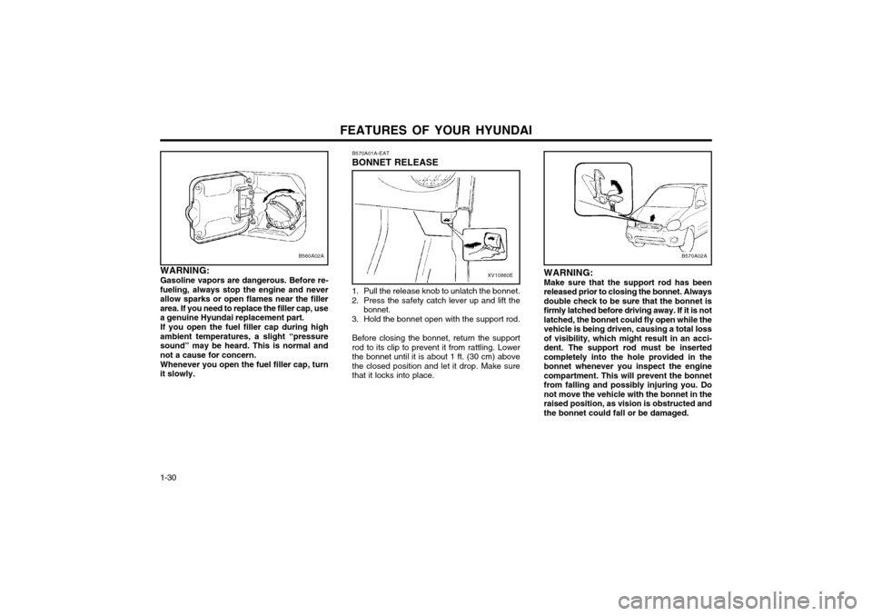
B570A02A
WARNING: Make sure that the support rod has been
released prior to closing the bonnet. Alwaysdouble check to be sure that the bonnet isfirmly latched before driving away. If it is notlatched, the bonnet could fly open while thevehicle is being driven, causing a total lossof visibility, which might result in an acci-dent. The support rod must be insertedcompletely into the hole provided in thebonnet whenever you inspect the enginecompartment. This will prevent the bonnetfrom falling and possibly injuring you. Donot move the vehicle with the bonnet in theraised position, as vision is obstructed andthe bonnet could fall or be damaged.
B570A01A-EAT BONNET RELEASE
B560A02A
WARNING: Gasoline vapors are dangerous. Before re-
fueling, always stop the engine and never allow sparks or open flames near the fillerarea. If you need to replace the filler cap, usea genuine Hyundai replacement part.
If you open the fuel filler cap during high
ambient temperatures, a slight “pressuresound” may be heard. This is normal andnot a cause for concern.
Whenever you open the fuel filler cap, turn
it slowly.XV10860E
1. Pull the release knob to unlatch the bonnet.
2. Press the safety catch lever up and lift the bonnet.
3. Hold the bonnet open with the support rod.
Before closing the bonnet, return the support rod to its clip to prevent it from rattling. Lowerthe bonnet until it is about 1 ft. (30 cm) abovethe closed position and let it drop. Make surethat it locks into place.
Page 203 of 249

WHAT TO DO IN AN EMERGENCY
3-2 3. If coolant is running out under the car or
steam is coming out from under the bonnet stop the engine. Do not open the bonnetuntil the coolant has stopped running or thesteaming has stopped. If there is no visibleloss of coolant and no steam, leave theengine running and check to be sure theengine cooling fan is operating. If the fan isnot running, turn the engine off.
4. Check to see if the water pump drive belt is missing. If it is not missing, check to see thatit is tight. If the drive belt seems to besatisfactory, check for coolant leaking fromthe radiator, hoses or under the car. (If theair conditioner had been in use, it is normalfor cold water to be draining from it).
WARNING: While the engine is running, keep hands andclothing away from moving parts such asthe fan and drive belts to prevent injury.
5. If the water pump drive belt is broken or coolant is leaking out, stop the engine imme-diately and call the nearest Hyundai dealerfor assistance.
WARNING: Do not remove the radiator cap when theengine is hot since steam and boiling watermay be ejected from the radiator resulting inburns or scalding.
CAUTION:
Personal injury and damage to the vehicle
may occur if jump starting is not performedcorrectly. If any doubt exists as to how thisoperation should be performed, seek assis-tance from qualified personnel. WARNING:
Motor vehicle batteries contain sulphuric
acid and emit hydrogen gas. Protective cloth- ing should be worn and care exercised toprevent the acid from coming into contactwith skin or clothing and the vehicle. Nakedlights should not be permitted in the vicinityof the battery. Care should be exercised topreventsparks occurring during connection.If acid accidentally comes into contact withskin or eyes, the affected area should imme-diately be flushed with copious amounts ofwater and medical assistance sought.
1. Ensure that the booster battery is 12 volt type. If the booster battery is installed in another vehicle, ensure that the two vehi-cles are not touching.
2. Turn off all unnecessary electrical equip- ment in both vehicles.
3. Ensure that the engine of the vehicle provid- ing the jump start is running prior to connec-tion of the jump cables.
4. Connect the red jump cable to the positive (+) terminal of the booster battery and theother end to the positive (+) terminal of thedischarged battery. 5. Attach the black jump cable to the negative
(-) terminal of the booster battery, and theother end to a ground point within the enginecompartment of the vehicle with the flat bat-tery. Do not connect to the negative batteryterminal of the flat battery since sparks maybe generated with the subsequent risk ofexplosion.
6. Raise the booster vehicle engine speed to 2,000 r.p.m. and start the engine of thevehicle with the flat battery.
7. Remove jump cables in the reverse order of installation (black cable first).
NOTE: If the jump cable is incorrectly installed, damage to the vehicle electrical system mayoccur, in particular the electronic compo-nents such as the Fuel Injection systemcomputer and the Automatic Transaxle com-puter. The battery must never be discon-nected whilst the engine is running. XD040A1-E
IF THE ENGINE OVERHEATS If the temperature gauge indicates overheating:
1. Pull off the road and stop as soon as it is safe to do so.
2. Place the gear selector lever in "P" (auto- matic), or neutral (manual transaxle, semi- automatic transalxe) and set the parkingbrake. If the air conditioner is on, turn it off.
Page 233 of 249

DO-IT-YOURSELF MAINTENANCE 6-15
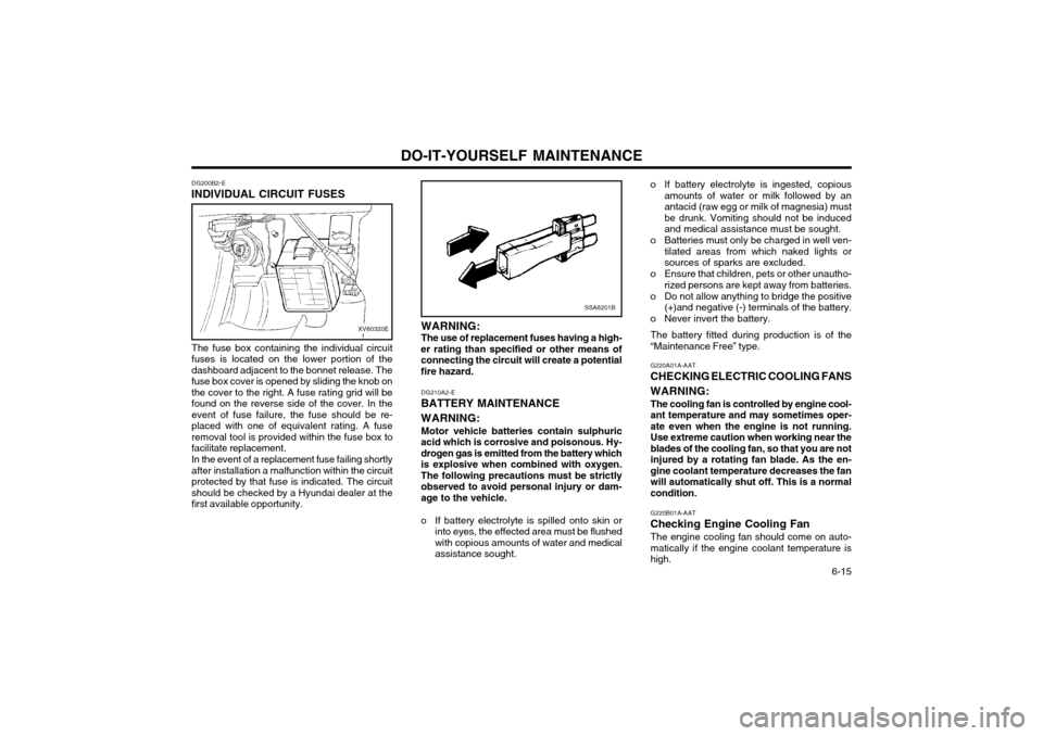
DG200B2-E
INDIVIDUAL CIRCUIT FUSES
XV60320E
The fuse box containing the individual circuit fuses is located on the lower portion of thedashboard adjacent to the bonnet release. Thefuse box cover is opened by sliding the knob onthe cover to the right. A fuse rating grid will befound on the reverse side of the cover. In theevent of fuse failure, the fuse should be re-placed with one of equivalent rating. A fuseremoval tool is provided within the fuse box tofacilitate replacement. In the event of a replacement fuse failing shortly after installation a malfunction within the circuitprotected by that fuse is indicated. The circuitshould be checked by a Hyundai dealer at thefirst available opportunity.
SSA6201B
WARNING: The use of replacement fuses having a high-
er rating than specified or other means of connecting the circuit will create a potentialfire hazard.
DG210A2-E
BATTERY MAINTENANCE WARNING:
Motor vehicle batteries contain sulphuric
acid which is corrosive and poisonous. Hy- drogen gas is emitted from the battery whichis explosive when combined with oxygen.The following precautions must be strictlyobserved to avoid personal injury or dam-age to the vehicle.
o If battery electrolyte is spilled onto skin or into eyes, the effected area must be flushed with copious amounts of water and medicalassistance sought. o If battery electrolyte is ingested, copious
amounts of water or milk followed by anantacid (raw egg or milk of magnesia) mustbe drunk. Vomiting should not be inducedand medical assistance must be sought.
o Batteries must only be charged in well ven- tilated areas from which naked lights orsources of sparks are excluded.
o Ensure that children, pets or other unautho- rized persons are kept away from batteries.
o Do not allow anything to bridge the positive (+)and negative (-) terminals of the battery.
o Never invert the battery.
The battery fitted during production is of the“Maintenance Free” type. G220A01A-AAT
CHECKING ELECTRIC COOLING FANS WARNING:
The cooling fan is controlled by engine cool- ant temperature and may sometimes oper-ate even when the engine is not running.
Use extreme caution when working near theblades of the cooling fan, so that you are notinjured by a rotating fan blade. As the en-
gine coolant temperature decreases the fanwill automatically shut off. This is a normalcondition. G220B01A-AAT
Checking Engine Cooling Fan The engine cooling fan should come on auto- matically if the engine coolant temperature ishigh.
Page 235 of 249

DO-IT-YOURSELF MAINTENANCE 6-17
WARNING: The halogen bulb contains gas under pres-
sure and if impacted could shatter, and re- sulting in flying fragments. Always wear eye
protection when servicing the bulb. Protectthe bulb against abrasions or scratches andagainst liquids when lighted. Turn on thebulb only when installing in a headlight.Replace the headlight if damaged or cracked.Keep the bulb out of the reach of childrenand dispose of the used bulb with care.
G290A01X-EAT
HEADLIGHT AIMING ADJUSTMENT
G290A01V
Before performing aiming adjustment, make sure
of the following.
Vertical aiming
1. Keep all tires inflated to the correct pres- sure.
2. Place the vehicle on level ground and press the front bumper & rear bumper down sev- eral times.
3. See that the vehicle is unloaded (except for full levels of coolant, engine oil and fuel, andspare tire, jack, and tools). Have the driveror equivalent weight placed in driver's seat.
4. Clean the head lights lens and turn on the headlight (Low beam).
5. Open the bonnet.
6. Draw the vertical line (through the center of each headlight) and the horizontal line(through the centre of each headlight) on theaiming screen.
1) Horizontal line dimension from ground:25.43 in. (646 mm)
2) Distance between each vertical line: 38.89 in. (988 mm)And then, draw the parallel line at 1.18 in. (30 mm) place under the horizontal line.
7. Adjust each cut-off line of the low beam to the parallel line with a phillips screwdriver -VERTICAL AIMING
8. Adjust each cut-off line of the low beam to the each vertical line with a phillips screw-driver - HORIZONTAL AIMING. G290B01X-EAT
Adjustment After Headlight Assembly Replacement
If the vehicle has had front body repair and the headlight assembly has been replaced, theheadlight aiming should be checked using theaiming screen as shown in the illustration. Turnon the headlight switch. (Low Beam Position)
1. Adjust headlights so that main axis of light is parallel to centre line of the body and isaligned with point "P" shown in the illustra-tion.
2. Dotted lines in the illustration show centre of headlights. G290B01S-DAG
Horizontal lineVertical line
W
0.59 in.
"P" 1.18 in.
Cut-off line
Ground line H
H L
Page 247 of 249

INDEX10-1
A ABS SYSTEM
..................................................................................... 2-7
ADJUSTABLE FRONT SEATS .......................................................... 1-5
AIR CLEANER FILTER ...................................................................... 6-8
AIR CONDITIONER CARE .............................................................. 6-12
AIR CONDITIONING SWITCH ......................................................... 1-36
AIR CONDITIONING OPERATION .................................................1-37
ANTENNA ......................................................................................... 1-52
APPEARANCE CARE ....... ........................................................ 4-1 ~ 4-2
ASHTRAY ......................................................................................... 1-25
AUDIO FAULT CODE ...................................................................... 1-49
AUTOMATIC TRANSAXLE ......................... .............................. 2-5 ~ 2-6
BBATTERY MAINTENANCE .............................................................. 6-15
BEFORE STARTING THE ENGINE .................................................. 2-2
BONNET RELEASE ......................................................................... 1-30
BRAKE CIRCUIT FAILURE WARNING LAMP ................................1-18
BRAKE PEDAL CLEARANCE ......................................................... 6-14
BRAKE PEDAL FREEPLAY ............................................................. 6-13
BRAKES ........................................................................................... 6-11
C
CARE OF SEAT BELTS .................................................................... 1-7
CARE OF CASSETTE TAPE ................................................ 1-50 ~ 1-51
CARE OF DISC ................................................................................ 1-50
CATALYTIC CONVERTER (For MFI ) ................................................ 7-1 CENTRAL DOOR LOCKING
SYSTEM ............................................. 1-7
CHANGING THE OIL AND FILTER .................. ....................... 6-4 ~ 6-5
CHARGING WARNING LIGHT ........................................................ 1-19
CHILD PROTECTOR REAR DOOR LOCKS .................................... 1-4
CHILD RESTRAINT SYSTEM ............................................... 1-10 ~ 1-11
CIGAR LIGHTER .............................................................................. 1-24
CLOCK .............................................................................................. 1-24
CLUTCH PEDAL FREEPLAY .......................................................... 6-13
COMPACT DISK PLAYER OPERATION (H922M) .............. 1-47 ~ 1-48
COMPRESSOR DRIVE BELT ......................................................... 6-12
COOLING FANS .............................................................................. 6-15
D
DAY-NIGHT REAR VIEW MIRROR .................................................1-26
DOOR LOCKS .................................................................................... 1-3DRIVE BELTS .................................................................................. 6-14
DRIVING FOR ECONOMY ................................................................ 2-8
EEFFECTIVE BRAKING ....................................................................... 2-7
EMERGENCY T OWING ..................................................................... 3-8
EMISSION CONTROL SYSTEM ......... .............................................. 7-1
ENGINE COMPARTMENT (For MFI Engine) .................................... 6-1
ENGINE COOLANT ........................................................................... 6-5
ENGINE COOLANT TEMPERATURE GAUGE ...............................1-20
ENGINE OIL CONSUMPTION ........................................................... 6-3
F
FILLING THE WASHER RESERVOIR .............................................. 6-9
FOLDING REAR SEAT BACK AND SEAT CUSHION ...................1-27
FOLDING THE OUTSIDE REAR VIEW MIRRORS ........................1-26
ZK000A1-E 10. INDEX
10