2002 HONDA CIVIC torque
[x] Cancel search: torquePage 591 of 1139

3.
Trailing Arm Removal/lnstallation
1.Raise the rear of the vehicle, and suppon it with
safety stands in the proper location (see page 1,8).
Remove the rear wheels.
Remove the knuckle (see page 18-28).
Place the floor jack under the trailing arm (A) to
support it.
B10 x 1.25 mm38Nm(3.9 kgl.m,28 tbf.ftl
12 x 1.25 mm61 N m (6.2 kgt m.
A 4s tbf,ft)
Remove the flange nut (B), and disconnect the
stabilizer link (C) from the trailing arm.
Remove the flange bolt {D), and disconnect the
damper (E) from the trailing arm.
Remove the trailing arm front mounting bolts (A).
A12 x 1.25 Jnm108 N.m {11.0 kgt.m,80 tbf.ft)
,'a':r -
7. Remove the trailing arm rear mounting bolt (A).
Do not loosen the special bolts (B) on the
trailing arm.
A12 x 1.25 mm59 N.m
-----\':,'.ttg
'.,--1..-r.':1
Lower the jack, and remove the trailing arm.
Install the trailing arm in the reverse order of
removal, and note these items:
. First install allthe suspension components and
lightly tlghten the bolts and nuts, then place ajack under the trailing arm, and raise the
suspension to load it with the vehicle's weight
before fully tightening the bolts and nuts to the
specified torque values.. Tighten allthe mounting hardware to the
specif ied torque values.. Before installing the wheel, clean the mating
surface of the brake disc and the inside of the
wneei.. Check the wheel alignment, and adjust it if
necessary (see page'18-4).
8.
9.
18-33
Page 594 of 1139

Rear Suspension
Damper/Spring Replacement (cont'dl
Disassembly/lnspection
1. Compress the damper spring with a commercially
available strut compressor (A) according to the
manufacturer's instructions. then remove the self-
locking nut (B)while holding the damper shaft (C)
with a hex wrench (D). Do not compress the spring
more than necessarv to remove the nut.
Release the pressure from the strut spring
compressor, then disassemble the damper as
shown ln the Exploded View.
Reassemble all the pans, except for the spring.
Compress the damper assembly by hand, and
check for smooth operation through a full stroke,
both compression and extension. The damper
should extend smoothly and constantly when
compression is released. lf it does not, the gas is
leaking and the damper should be replaced.
?
4.
Check for oil leaks, abnormal noises, or binding
during these tests.
18-36
Reassembly
1. Install allthe partsexceptthe self-locking nutonto
the damper unit by referring to the Exploded View.
Align the bottom of the spring {A} and the stepped
part of the lower spring seat (B), and align the
damper mounting base as shown,
,, '161 7fi)1,, "
\3P qY/
Installthe damper assembly on a commercially
available strut spring compressor (C).
Compress the damper spring with the spring
compressor.
Installthe new self'locking nut (A) on the damper
shaft.
10 x 1.25 mm29Nm(3.0 kgt m,22 lbt.ft)
5. Hold the damper shaft {B) with a hex wrench (C),
and tighten the self-locking nut to the specified
torque.
Page 595 of 1139

D
Installation
1. Position the damper assembly in the body. Note
the direction of the damper mounting base so that
the small hole dot on it is toward the front and
inside of the vehicle.
Loosely install the flange nuts (A) onto the top of
the damper,
A10 x 1.25 mm59 N.m16.0 kgt.m, ia lbt ft)
3. Loosely installthe flange bolt (A) on the bottom of
the damper.
12x 1.25 mm61 N m {6.2 kgf.m. 45 lbf.ft)
Raise the suspension with a floor jack to load the
vehicle weight, and tighten the nuts and bolt to the
specified torque values.
Clean the mating surface ofthe brake disc and the
inside of the wheel, then install the rear wheel.
Check the wheel alignment, and adjust it if
necessary (see page 18-4).
18-37
Page 607 of 1139

Conventional Brake Gomponents
Front Brake Pads Inspection and Replacement (cont'dl
3. Remove the pad retainers (A), and check the caliperpins for free movement.
/:-."
t-... .,.';-iri.: '1=' r
.. a.-
4. Clean the caliper thoroughly; remove any rust, andcheck for grooves and cracks.
5. Checkthe brake disc for damage and cracks.
6. Apply Dow Corning Molykote M77 grease to theretainers on their mating surfaces against thecaliper bracket.
7. Installthe pad retainers. Wipe excess grease offtheretainers. Contaminated brake discs and pads
reduce stopping ability. Keep grease off the discsand pads.
8. Apply Molykote l\477 grease to both sides of thepad shim {A), the back ofthe pads (B), and the other
areas indicated by the arrows.
Wipe excess grease off the shim. Contaminated
brake discs and pads reduce stopping ability. Keepgrease off the discs and pads.
Installthe brake pads and pad shim correctly.Install the pads with the wear indicators (C) on theinside.
lf you are reusing the pads, always reinstall thebrake pads in their original positions to prevent amomentary loss of braking efficiency.
, a .).
19-12
10. Push in the piston (A) so the caliper will fitoverthepads. Check the brake fluid level. The brake fluid
may overflow if the reservoir is too full. lvlake surethe piston boot is in position to prevent damaging itwhen pivoting the caliper down
8x1.0mm34 N.m3.5 kgt m.25 tbf.ft)
11. Pivot the caliper down into position. Being carefulnot to damage the pin boots, install the bolt (B), and
tighten it to the specified torque.
12. Press the brake pedal several timestomakesure
the brake works, then test drive.
NOTE: Engagement of the brake may require agreater pedal stroke immediately after the brakepads have been replaced as a set. Several
applications of lhe brake pedal will restore thenormal pedal stroke.
13. After installation, check for leaks at hose and linejoants or connections, and retighten if necessary.
\
Page 608 of 1139

Front Brake Disc lnspection
Runout
1. Raise the front of the vehicle, and support it with
safety stands in the proper location (see page 1-8).
Remove the front wheels.
2. Remove the brake pads (see page 19-11).
3. Inspect the disc surface for damage and cracks.
Clean the disc thoroughly, and remove all rust
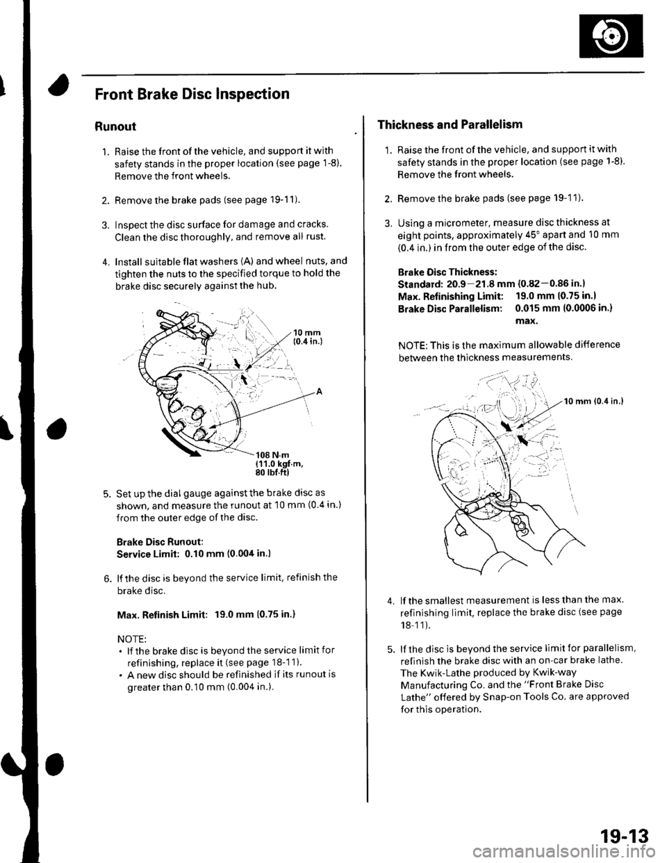
4. lnstall suita ble flat washers (A) andwheel nuts,and
tighten the nuts to the specified torque to hold the
brake disc securely against the hub.
Set up the dial gauge against the brake disc as
shown, and measure the runout at 10 mm (0 4 in.)
from the outer edge of the disc.
Brake Disc Runout:
Service Limit: 0.10 mm (0.00tt in.l
lf the disc is beyond the service limit, refinish the
brake disc.
Max. Retinish Limit: 19.0 mm (0.75 in.)
NOTE:. lf the brakedisc is beyondtheservice limitfor
refinishing, replace it (see page 18-1 1).
. A new disc should be refinished if its runout is
greater than 0.10 mm (0.004 in.).
Thickness and Parallelism
1. Raise the front of the vehicle, and support it with
safety stands in the proper location (see page 1-8).
Remove the front wheels.
2. Remove the brake pads (see page 19-11).
3. Using a micrometer, measure disc thickness at
eight points, approximately 45" apart and 10 mm
{0.4 in.) in from the outer edge of the disc.
Brake Oisc Thickness:
Standard: 20.9 21.8 mm {0.82-0.86 in.}
Max. Refinishing Limit: 19.0 mm 10.75 in.)
Brake Disc Parallelism: 0.015 mm 10.0(X)6 in.)
max.
NOTE: This is the maximum allowable difference
between the thickness measurements
10 mm lo.it in.l
lf the smallest measurement is less than the max.
refinishing limit, replace the brake disc (see page
18-11).
lf the disc is beyond the service limit for parallelism,
refinish the brake disc with an on-car brake lathe.
The Kwik-Lathe produced by Kwik-way
Manufacturing Co. and the "Front Brake Disc
Lathe" offered by Snap-on Tools Co. are approved
for this operation.
4.
': . --'t-'"'-
t,.
19-13
Page 611 of 1139

Conventional Brake Components
Master Cylinder Inspection
NOTE:. Before reassembling, check that al I parts are f ree ofdust and other foreign particles.. Do nottryto disassemblethe mastercylinder
assembly. Replace the master cylinder assembly witha new part if necessary.. Do not allow dirt or foreign matter to contaminate thebrake fluid.
RESERVOIB CAPI unecK Ior otocKageof vent holes.
RESERVOIR
,--l RESERvOIR SEALCheck lor damaoe
RESERVOIR HOSESInspect hoses fordamage, leaks, anddeterioration.
r',,.J\+
v
MASTER CYLINDERCheck for leaks, rust, and damage
and deterioration.
STRAINERRemove accumulatedseotment.
19-16
Brake Booster Pushrod Clearance
Adjustment
SpecialTools Required
Pushrod adjustment gauge 07JAG-SD40100
NOTE: Brake booster pushrod-to-piston clearance mustbe checked and adjustments made, if necessarV, beforeinstalling the master cylinder.
1. Setthespecial tool (A) onthe mastercylinder bodv(B), push in the center shaft (C) until the top of itcontacts the end of the secondary piston {D) byturning the adjusting nut (E).
Without disturbing the center shaft's position,
installthe specialtool (A) backwards on the booster.
Install the master cylinder nuts (B), and tighten
them to the specified torque.
Connecl the booster in line with a vacuum gauge
{C) 0-101 kPa {0'-760 mmHg, 30 in.Hg) to thebooster's engine vacuum supply, and maintain anengine speed that will deliver 66 kPa (500 mmHg,20 in.Hg) vacuum.
15 N m {r.511 tbf.ftl
Page 616 of 1139

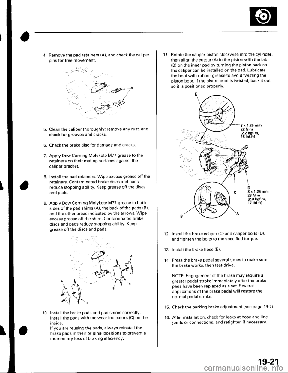
4. Remove the pad retainers (A). and check the caliper
pins for free movement.
:.i _ _l
7.
8.
5. Clean the caliper thoroughly; remove any rust. and
check for grooves and cracks.
6, Check the brake disc for damage and cracks.
Apply Dow Corning Molykote M77 grease to the
retainers on their mating surfaces against the
caliper bracket,
Installthe pad retainers. Wipe excess grease offthe
retainers. Contaminated brake discs and pads
reduce stopping ability. Keep grease off the discs
and pads.
Apply Dow Corning Molykote lvl77 grease to both
sides of the pad shims {A), the back of the pads (B),
and the other areas indicated by the arrows. Wipe
excess grease off the shim. Contaminated brake
discs and pads reduce stopping ability. Keep
grease off the discs and pads.
9.
..-.
10. Installthe brake pads and pad shims correctly.
Installthe pads wirh the wear indicators {C) on the
inside.
lf you are reusing the pads, always reinstall the
brake pads in their original positions to prevent a
momentary loss of braking efficiency.
11. Rotate the caliper piston clockwise into the cylinder,
then align the cutout (A) in the piston with the tab
{B) on the inner pad by turning the piston back so
the caliper can be installed on the pad. Lubricate
the boot with rubber grease to avoid twisting the
Diston boot. lf the piston boot is twisted, back it out
so it is positioned properly.
8 x 1.25 mm22 N.ml2.2 kgt m,16 rbl.ttl
.ar
D8 x 1.25 mm23Nm{2.3 kgf.m,17 rbf.ft)
13.
14.
Installthe brake caliper (C) and caliper bolts (D).
and tighten the bolts to the specified torque.
Installthe brake hose (E).
Press the brake pedal several times to make sure
the brake works, then test-drive.
NOTE: Engagement of the brake may require a
greeter pedal stroke immediately after the brake
pads have been replaced as a set. Several
applications of the brake pedal will restore the
normal pedal stroke,
15. Check the parking brake adjustment {see page 19-7).
16. After installation, check for leaks at hose and line
joints or connections, and retighten if necessarY.
19-21
Page 617 of 1139

Conventional Brake Components
Rear Brake Disc Inspection
Runout
1. Raise the rear of the vehicle, and support it with
safety stands in the proper location (see page 1-8).Remove the rear wheels,
2. Remove the brake pads (see page 19-20).
3. Inspect the disc surface for damage and cracks.
Clean the disc thoroughly, and remove all rust,
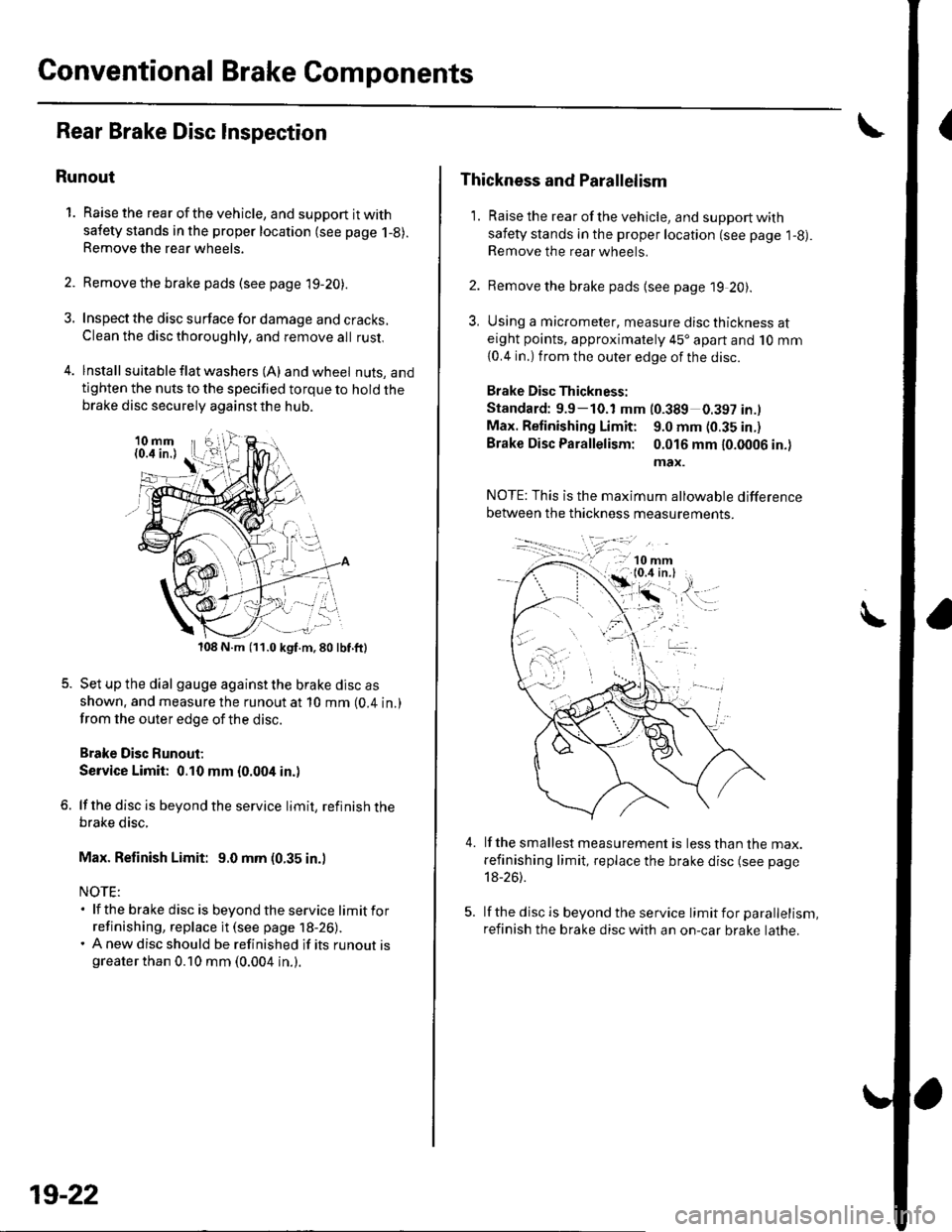
4. lnstall suita ble f lat washers (A) and wheel nuts, andtighten the nuts to the specified torque to hold thebrake disc securely against the hub.
108 N.m (11.0 kgf.m,80lbf.ft)
Set up the dial gauge against the brake disc as
shown. and measure the runout at 10 mm (0.4 in.)
from the outer edge of the disc.
Brake Disc Runout;
Service Limit: 0.10 mm {0.004 in.)
lf the disc is beyond the service limit, refinish thebrake disc.
Max. Refinish Limit: 9.0 mm (0.35 in.)
NOTE:. lf the brake disc is beyondtheservice limitfor
refinishing, replace it (see page 18-26).. A new disc should be refinished if its runout isgreater than 0.10 mm (0.004 in.).
19-22
Thickness and Parallelism
1. Raise the rear of the vehicle, and support with
safety stands in the proper location (see page l-g).Remove the rear wheels.
2. Remove the brake pads {see page 19 20).
3, Using a micrometer, measure disc thickness ateight points, approximately 45'apart and 10 mm
{0.4 in.) from the outer edge of the disc.
Brake Disc Thickness:
Standard: 9.9-10.1 mm (0.389 0.397 in.l
Max. Retinishing Limit: 9.0 mm (0.35 in.)
Brake Disc Parallelism: 0.016 mm 10.0006 in.)
max.
4.lf the smallest measurement is less than the max.
refinishing limit, replace the brake disc (see page
18-26).
lf the disc is beyond the service limit for parallelism,
refinish the brake disc with an on-car brake lathe.