Page 656 of 1139
Doors
Component Location Index
POWER WINDOWswtTcH
a
DOOR SASH TRIMReplacement, page 20-10
DOOR GLASS OUTERWEATHERSTRIPReplacement, page 20-10
DOORPosition Adiustment,page 20-12
t
\POWER DOOR LOCK SWITCH(Driver's)
DOOR OUTER TRIM
K-pIJ A'A
dq
W2"'
Ya\J aita.
DOOR WEATHERSTRIPReplacement, page 20-'l'l
20-2
Page 832 of 1139

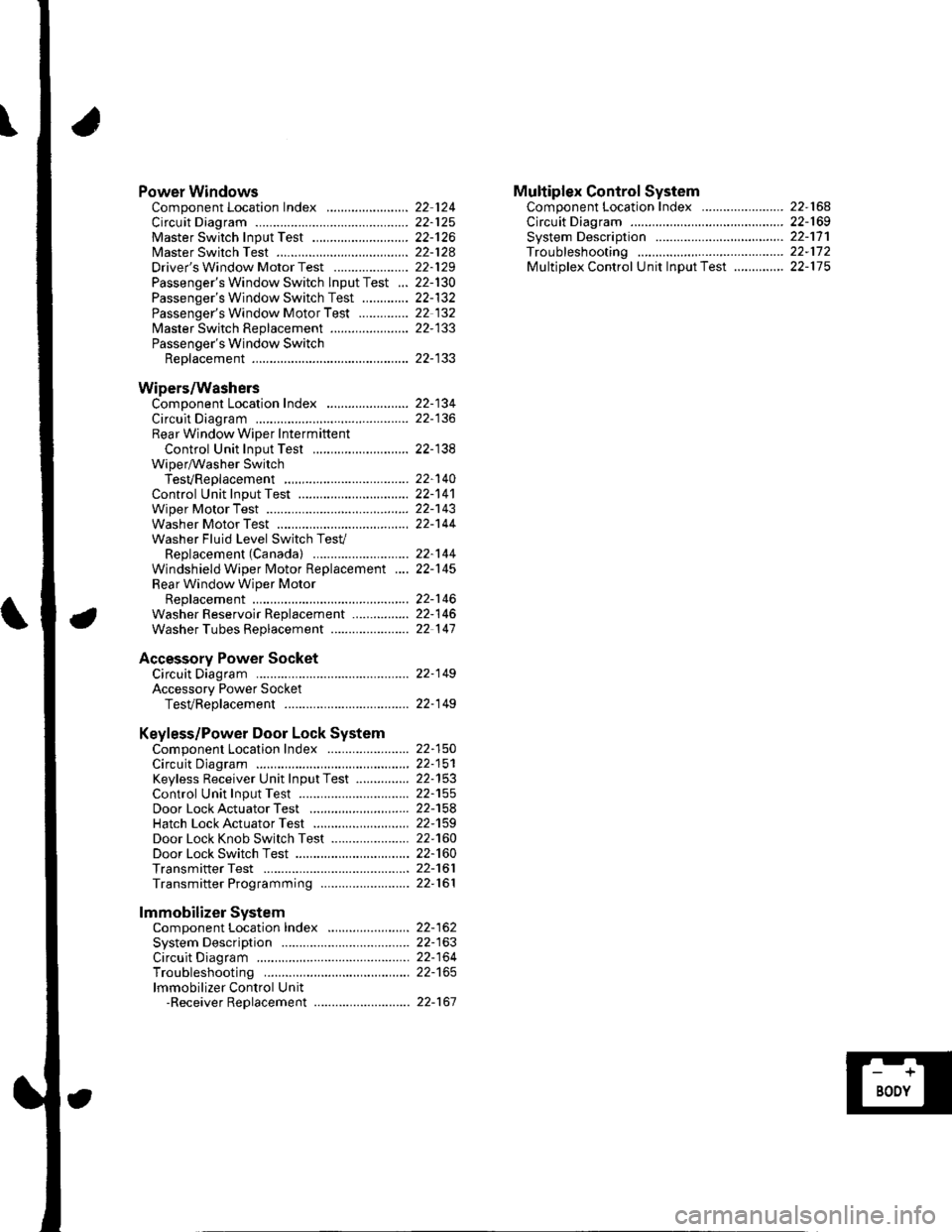
Power WindowsComponent Location Index ..........
circuit Diagram . .. ............... .........:.::::.::::.:Master Switch Input Test ...........................Master Switch TestDriver's Window Motor Test .....................
Passenger's Window Switch lnput Test ...Passenger's Window Switch Test .............
Passenger's Window Motor Test ..............
lMaster Switch Replacement ......................
Passenger's Window SwitchReplacement
Wipers/WashersComponent Location Index .......................
Circuit DiagramRear Window Wiper Intermiftent
Control Unit Input Test ...........................Wiper/Washer SwitchTesVReplacementControl Unit Input Test ...............................Wiper Motor Test
Washer Motor TestWasher Fluid Level Switch TesV
Replacement (Canadal ..........................
Windshield Wiper Motor Replacement ....
Rear Window Wiper MotorReplacementWasher Reservoir Replacement ................
Washer Tubes Beplacement ......................
Accessory Power SocketCircuit Diagram ......... 22-149
Accessory Power Socket
TesVReplacement ................................... 22-1 49
Keyless/Power Door Lock System
Component Location Index ....................... 22-150
Circuit Diagram ......... 22-151Keyless Receiver Unit InputTest ............... 22-153
Control Unit Input Test ............................... 22-155
Door LockActuatorTest .........,.......,..,.,..... 22-158Hatch LockActuatorTest ........................... 22-159
Door Lock Knob Switch Test ...................... 22-160
Door Lock Switch Test ................................ 22-160
Transmitter Test ....... 22-161
Transmitter Programming ......................... 22-161
Multiplex Control SystemComponent Location Index ...........
circuit Diagram ...... ........................::.:..:.::.:
Svstem DescriDtionTroubleshootingMultiolex Control Unit InDut Test .............
22 12422-12522-12622-12822-129
22- t30
22-13222 13222-133
22-133
22-134
22-138
22-14022-14122-14322-144
22-14422-145
22-14622-14622 147
22,16422-16922-17'l22,11222-175
lmmobilizer Systemcomponent Location Index ...........
System Description ....... ............. ..:..:..:.:...
Circuit DiagramTroubleshootinglmmobilizer Control Unit-Receiver Replacement ...........................
22-16222-16322-164
22-167
Page 955 of 1139
Power Windows
IJComponent Location Index
DRIVER'S WINDOW MOTORTest, page 22-129
UNDER.DASHFUSE/RELAY BOX
POWER WINDOW RELAYIest, page 22-51
FRONT PASSENGER'SWINDOW MOTORTest, page 22-132
tJ
POWER WINDOW MASIER SWITCHInput Test. Daqe 22.126Test, page 22--128Replacement, page 22-133
FRONT PASSENGER'S WINDOW SWITCHInDut Tesl, paqe 22-130f est, page 22-132Beplacement, page 22-133
al.l ' -f..--.--
L-.::
22-124
\J
Page 957 of 1139
Power Windows
Master Switch Input Test
NOTE: The power window control unit is built into the power window master switch, and it only controls the driver'swindow operations.
1. Remove the window master switch {A) (see page 22-133).
2. Disconnect the 14P connector (B) from the master switch.
GRN/WHT
3. Inspect the co nnector and socket terminals to be sure they are all making good contact.
. lf theterminals are bent, loose orcorroded, repairthem as necessary, and recheckthe system.. lf the terminals look OK, go to step 4.
22-126
Page 961 of 1139

Power Windows
1.
2.
Passenger's Window Switch Input Test
Remove the switch panel (see page 20-4).
Disconnect the 5P connector (A) from the switch (B).
o
'' "'"1.
4.
Wire side of female terminals
BLU/WHTGRN/BLK
Input the connector and socket terminals to be sure they are all making good contact.
. lf theterminals are bent, loose or corroded, repairthem as necessary, and recheckthe system.. lf the terminals look OK, go to step 4.
Reconnect the connector, and using a back probe, make these input tests at the connector. lf any test indicates aproblem, find and correct the cause, then recheck the svstem,
CavitvWireTest conditionTest: Desired resultPossible cause if result is not obtained
3GRN/BLKlgnition switch ON
{ ll)
Check for voltage to
grouno:
There should be battery
voltage.
Blown No.6 (7,5A)fuse in the
under-dash fuse/relay box
Blown No.22 {20A)fuse in the
under-dash fuse/relay box
Faulty power window relay
An open in the wire
Poor qround (G201)
2BLD,A/VHTlgnition switch ON( )
At the master
window switch,
press and hold
down the
passenger's switch
Check for voltage to
ground:
There should be battery
voltage.
Faulty master window switch
An open in the wire
BLU/REDlgnition switch ON(||)
At the master
window switch,
pull up and hold
the passenger's
switch
Check for voltage to
grouno:
There should be battery
voltage.
Faulty master window switch
An open in the wire
22-130
Page 963 of 1139
Power Windows
1.
Passenger's Window Switch Test
Remove the switch panel (see page 20-4).
Remove the power window switch (A) from the
door panel.
Disconnect the 5P connector (B) from the
passenger's power window switch.
Check for continuity between the terminals in each
switch position according to the table.
lf the continuity is not as specified, replace the
swtlcn.
tfiTtTtT;Etll' '-r--r-,Jl
\TorminalPoiition\124
UP
OFF
DOWN
22-132
Passenger's Window Motor Test
1.Remove the passenger's door panel (see page 20-
4).
Disconnect the 2P connector (A) from thepassenger's power window motor.
Terminal side ofmale terminals
Test the motor in each direction by connecting
battery power and ground according to the table.
When the motor stops running, disconnect one
lead immediately.
Terminal
Dl*;;;__\1
UPI
o
o
DOWNo
lf the motor does not run or fails to run smooth ly,
reptace rt.