Page 520 of 1139

'I 1.Substitute a known-good EPS control unit, and
connect the all disconnected connectors.
Sta rt the engine.
Does the EPS indicator come on?
YES Go to step 13.
NO Check for loose EPS control unitconnectors. lf
necessary, replace the EPS control unit and
retest.l
Stop the engine, and verify the DTC.
ls DTCl2 indicated?
YES Check for loose torque sensor connectors.
lf necessary, substitute a known-good steering
gearbox and recheck.l
NO-Perform the appropriate troubleshooting for
the code indicated. !
12.
13.
DTC 16: Torque Sensor VT3 and W6
1. Clear the DTC.
2. Start the engine.
3. Wait at least 10 seconds.
Does the EPS indicator come on?
YES Go to step 4.
NO Check for loose wires or poor connnections. lf
the connections are good, the system is OK at this
time.l
4. Stop the engine, and verify the DTC.
ls DTC16 indicated?
YES-Go to step 5.
NO Perform the appropriate troubleshooting for
the code indicated. t
5. Make sure the ignition switch is OFF, then
disconnect EPS control unit connector C (20P) and
the torque sensor 6P connector.
6, Check for continuity between the appropriate EPS
control unit connector C (20P) terminal and body
ground (see table).
Terminal nameEPS control unit connector C
terminal No.
Vccl3
Vcc211
VT313
VT65
T/S GND2
W re s d€ oltemalelermi.als
ls there continuity?
YES- Repair short to body ground in the
appropriate sensor circuit between the torque
sensor and EPS control unit, !
NO Go to step 7.
{cont'd)
EPS CONINOT UNITCONNECIOR C (2OP)
17-29
Page 521 of 1139

EPS Components
I
7.
8.
DTC Troubleshooting (cont'd)
Turn the ignition switch ON (ll).
Measure the voltage between the appropriate EPS
control unit connector C (20P) terminal and bodyground (see table).
Terminal nameEPS control unit connector C
terminal No.
Vccl3
Vcc211
VT313
VT65
T/S GND2
ls thete battery voltage?
YES Repair shon to power in the + circuit wire
between the EPS control unit and torque sensor.l
NO Go to step 9.
EPS CONTROL UNIT CONNECTOR C {2OP}
Wire side of female terminals
17-30
9.
10.
Turn the ignition switch OFF.
Check for continuity between the appropriate EPS
control unit connector C {20P) terminal and the
torque sensor terminal (see table).
TOROUE SENSOR 6P CONNECTOR
Vccz(GRN/YELI
Wire side offemale terminals
VT6 {YEL/RED)
EPS CONTROL UNITCONNECTOR C I2OP)
VT6 {YEL/RED}
\
Wire side of female terminals
ls there continuty?
YES Go to step 11.
NO Repair open in the appropriate torque sensor
wire circuit between the EPS control unit and the
torque sensor.l
\
Terminal
name
Torque Sensor
terminal No,
EPS control
unit connector
C terminal No.
Vccl23
Vcc2311
VT3'l't3
VT665
T/S GND62
T/S GND {PNK)
Page 522 of 1139

11.
't2.
Substitute a known-good EPS control unit, and
reconnect the disconnected connectors.
Sta rt the engine.
Does the EPS indicator come on?
YES Go to step 13.
NO Check for loose or poor connections at the
EPS control unit and the torque sensor conneclors.
lf the connections are good, replace the EPS control
unit and recheck.I
Stop the engine, and verify the DTC.
ls DTC16 indicated?
YES Replace the steering gearbox and recheck.l
NO Perform the appropriate troubleshooting for
the code indicated.l
13.
DTC 17: Torque Sensor Vccl
DTC 18: Torque Sensor Vcc2
1. Clear the DTC.
2. Start the engine.
3. Wait at least 10 seconds.
4.
Does the EPS indicator come on?
YES Go to step 4.
NO Check for loose wires or poor connections. lf
the connections are good, the system is OK at this
time.I
Stop the engine, and verify the DTC.
Is DTCl7 or DTCl8 indicated?
YES Go to step 5.
NO Do the troubleshooting for the DTc
indicated.I
Make sure the ignition switch is OFF, then
disconnect EPS control unit connector C (20P) and
the torque sensor 6P connector.
Check for continuity between EPS control unit
connector C (20P)terminal No. 3 and body ground.
EPS CONTROL UNIT CONNECTOR C (2OP)
Wire side o{ female terminals
ls there continuity?
YES Repair shon to body ground in the wire
between the torque sensor and EPS control unit.I
NO Go to step 7.
(cont'd)
17-31
Page 523 of 1139

EPS Components
DTC Troubleshooting (cont'dl
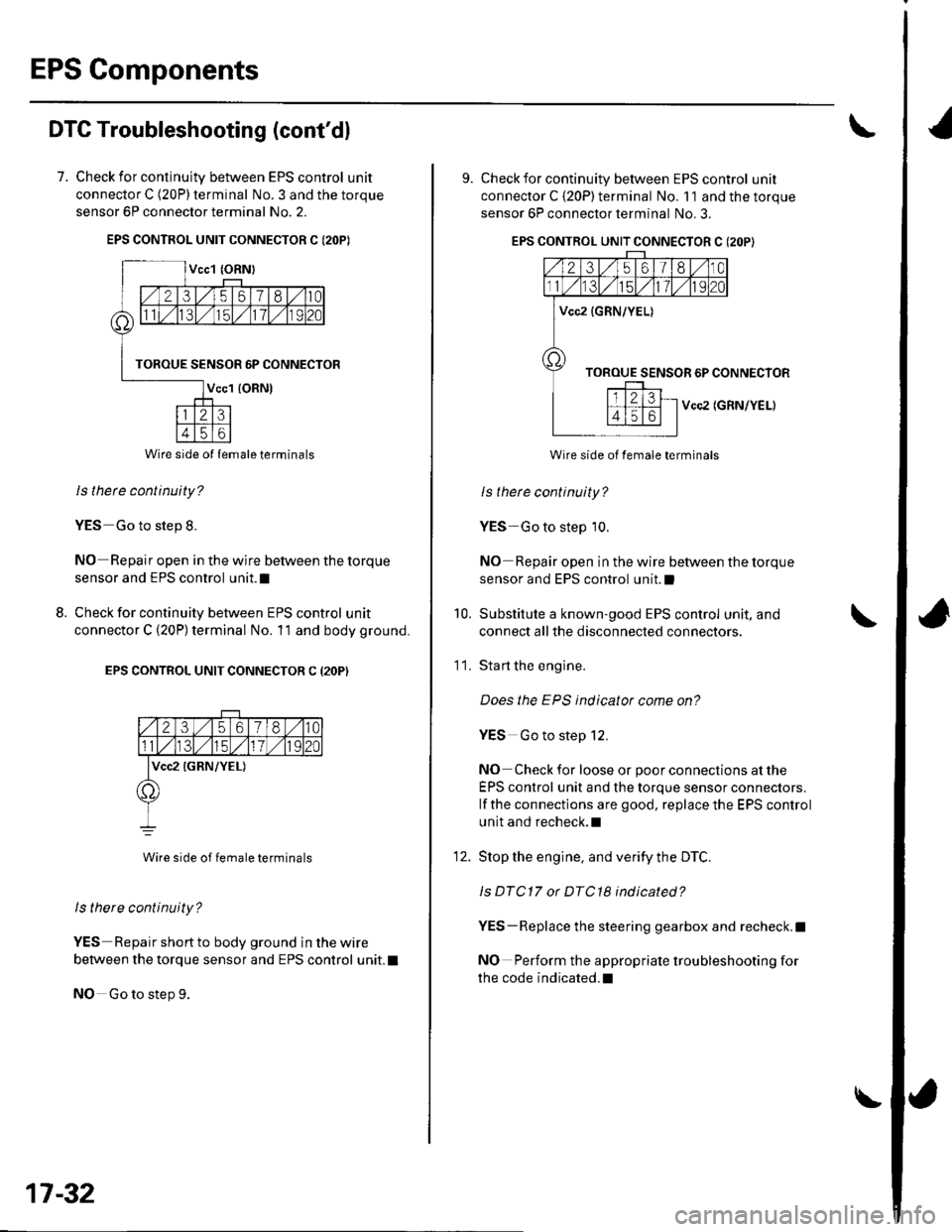
7. Check for continulty between EPS control unit
connector C (20P) terminal No. 3 and the torque
sensor 6P connector terminal No. 2.
EPS CONTROL UNIT CONNECTOR C I2OP)
ls thete continuity?
YES Go to step 8.
NO Repair open in the wire between the torque
sensor and EPS control unit.I
Check for continuity between EPS control unit
connector C (20P) terminal No. 11 and body ground.
EPS CONTROL UNIT CONNECTOR C (2OP)
2356180
lvcc2 {GRN/YEL)
Wire side of female terminals
ls there continuity?
YES Repair short to body ground in the wire
between the torque sensor and EPS control unit. t
NO Go to step 9.
8.
Wire side ol lemale terminals
17-32
\
9. Check for continuity between EPS control unit
connector C {20P) terminal No. 11 and the torque
sensor 6P connector terminal No. 3.
EPS CONTROL UNIT CONNECTOR C (2OP}
Vcc2 (GRN/YEL)
Wire side of female terminals
ls therc continuity?
YES-Go to step 10.
NO Repair open in the wire between the torque
sensor and EPS control unit.l
Substitute a known-good EPS control unit, and
connect all the disconnected connectors.
Sta rt the engine.
Does the EPS indicator come on?
YES Go to step 12.
NO Check for loose or poor connections at the
EPS control unit and the torque sensor connectors.
lf the connections are good, replace the EPS control
unit and recheck.l
Stop the engine, and verity the DTC.
ls DTC17 or DTC18 indicated?
YES-Replace the steering gearbox and recheck.l
NO Perform the appropriate troubleshooting for
the code indicated.l
10.
11.
12.
Page 536 of 1139

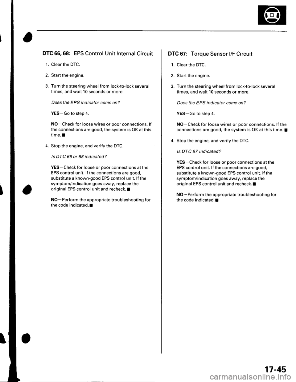
DTC 66,68: EPS Control Unit lnternal Circuit
1. Clear the DTC.
2. Sta rt the engine.
3. Turn the steering wheel from lock-to-lock several
times, and wait 10 seconds or more.
Does the EPS indicator come on?
YES-Go to step 4.
NO-Check for loose wires or poor connections. lf
the connections are good. the system is OK at this
time.l
4. Stop the engine. and verify the DTC.
ls DTC 66 or 68 indicated?
YES-Check for loose or poor connections at the
EPS control unit. lf the conneclions are good,
substitute a known-good EPS control unit. lf the
symptom/indication goes away, replace the
original EPS control unit and recheck.I
NO Perform the appropriate troubleshooting for
the code indicated. t
DTC 67: Torque Sensor l/F Circuit
1. Clear the DTC.
2. Start the engine.
3. Turn the steering wheelfrom lock-to-lock several
times, and wait 10 seconds or more.
Does the EPS indicator come on?
YES-Go to step 4.
NO Check for loose wires or poor connections. lf the
connections are good, the system is OK at this time. !
4. Stop the engine, and verify the DTC.
ls DTC 67 indicated?
YES Check for loose or poor connections at the
EPS control unit. lf the connections are good,
substitute a known-good EPS control unit. lf the
symptom/indication goes away, replace the
original EPS control unit and recheck. !
NO-Perform the appropriate troubleshooting for
the code indicated.I
17-45
Page 544 of 1139
17. Remove the bodv stiffener (A).
Remove lhe steering stiffener A from the left side
of the steering gearbox.
18.
19. Remove the steering stiffener B from the right side
of the steering gearbox.
i t1-:: .,
20. Lower the steering gearbox, and rotate it so the
pinion shaft points upward.
21. Remove the pinion shaft grommet (A) from the top
of the torque sensor.
(cont'd)
17-53
Page 550 of 1139

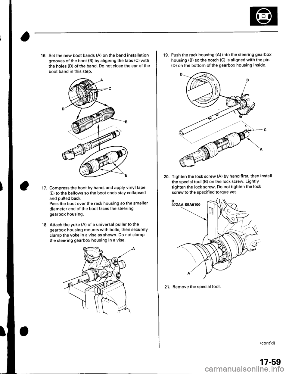
16. Set the new boot bands (A) on the band installation
grooves of the boot (B) by aligning the tabs (C) with
the holes (D) of the band. Do not close the ear of the
boot band in this step.
Compress the boot by hand, and apply vinyl tape
(E) to the bellows so the boot ends stay collapsed
and pulled back.
Pass the boot over the rack housing so the smaller
diameter end of the boot faces the steering
gearbox housing.
Attach the yoke (A) of a universal puller to the
gearbox housing mounts with bolts. then securely
clamp the yoke in a vise as shown. Do not clamp
the steering gearbox housing in a vise.
11.
18.
'19. Push the rack housing (A) into the steering gea rbox
housing (B) so the notch (C) is aligned with the pin
(D) on the bottom of the gearbox housing inside
20. Tighten the lock screw {A) by hand first, then install
the special tool (B) on the lock screw. Lightly
tighten the lock screw. Do not tighten the lock
screw to the specified torque Yet.
21. Remove the special tool.
(cont'd)
17-59
Page 551 of 1139

EPS Components
{Steering Gearbox Overhaul (cont'dl
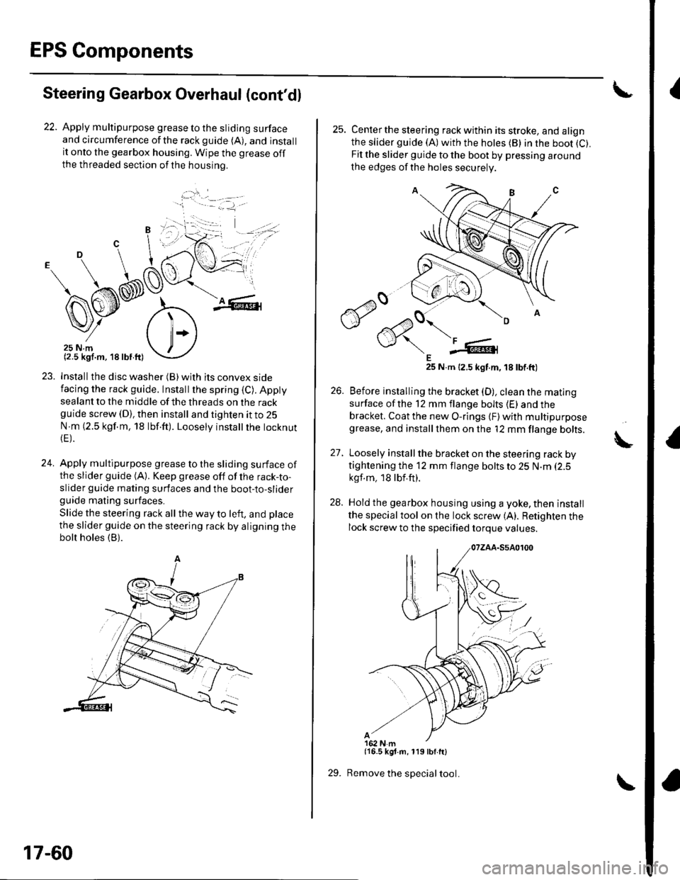
22. Apply multipurpose grease to the sliding surfaceand circumference ofthe rackguide (A), and installit onto the gearbox housing. Wipe the grease offthe threaded section ofthe housrno.
...'.
,. ,l
.j
23. Installthe disc washer (B)with its convex sidefacing the rack guide. Installthe spring (C). Appty
sealant to the middle of the threads on the rackguide screw (D), then install and tighten it to 25
N m (2.5 kgf.m, 18 lbf.ft). Loosely instatlrhe tocknut(E).
24. Apply multipurpose grease to the sliding surface ofthe slider guide (A). Keep grease off of the rack-to-slider guide mating surfaces and the boot-to-sliderguide mating surfaces.
Slide the steering rack all the way to left, and place
the slider guide on the steering rack by aligning thebolt holes (B).
'1 - .- =-1, -
17-60
29.
25. Centerthe steering rack within its stroke, and alignthe slider guide (A)with the hotes (B) in the boot (C).
Fit the slider guide to the boot by pressing around
the edges of the holes securely
E25 N.m 12.5 kgt.m, 18 tbt.ft)
26. Before installing the bracket (D), clean the mating
surface ofthe 12 mm flange bolts (E) and thebracket. Coat the new O-rings {F) with multipurposegrease, and installthem on the '12 mm flange bolts.
27. Loosely install the bracket on the steering rack bytightening the 12 mm flange bolts to 25 N.m (2.5
kgf.m, 18lbf.ft).
28. Hold the gearbox housing using a yoke, then install
the specialtool on the lock screw (A). Retighten thelock screw to the specified torque values.
{16.5 kgt.m, 119 lbf.ft}
Remove the special tool.
A