Page 766 of 1139
Frame
Subframe Replacement
Subframe Torque
NOTE: After loosening the subframe mounting bolts, be sure to replace them with new ones.
Reference holes alignment:
SUBFRAMEREFERENCE HOLE(Body Side)
INSTALLATIONREFERENCE HOLE(Subframe side)
INSTALLATIONREFERENCE HOLE
FRONT SUSPENSIONSCREWDRIVERor TAPERED PUNCHINSTALLATIONREFERENCE HOLE
SPECIAL BOLTS'14 x 1.5 mm103 N.m(10.5 kgf.m,75lbf.ft)Replace.
To body.
To body.I
n
E
20-112
Page 767 of 1139
Frame Stiffener, Brace, and Gusset Replacement
Frame Stiffener, Brace, and Gusset Torque
NOTE: When installing the middle floor cross member brace or gussets, torque the mounting hardware in the
following sequence to avoid damage to the quarter panel.
MIDDLE FLOORCROSS-MEMgERBRACE/GUSSET
SIDE FRAME STIFFENER
8 x 1.25 mm29 N.m(3.0 kgf m,22 lbf ft)
U.S. model:
10 x 1.25 mm38 N.m(3.9 kgf.m.28lbf.ftl
To body.
Canada model:
MIDDLE FLOORCROSS.MEMBERGUSSET
MIODLE FLOORCROSS-MEMBERBRACE
.. __!:::-- | -
10 x 1.25 mm38 N m (3.9 kgt.m, 28 lbf.ftl
10 x 1.25 mm38Nm(3.9 kgf.m,28 lbl.ftl
I
20-113
Page 855 of 1139
Connectors and Harnesses
Connector to Harness lndex (cont'dl
EPS Subharness
Connector or TerminalCavitiesLocationConnects toNotesEPS control unit connectorAEPS control unit connector BEPS control unit connector CEPS motorEPS torque sensorc 151
c152
2,l
31
6
4
2220262
I
Under rightside ofdashUnder right side of dashUnder righr side of dashMiddle of engine companmentMiddle of engine compartmentUnder right side of dash
Under right side of dash
Engine compartment wireharness (see page 22- 18)ECI\,4 wire harness (see page22-321G 1515aody ground via EPS
22-24
Page 1023 of 1139

sRs
Precautions and Procedures {cont'dl
SRS Unit, Front lmpact Sensors, and Side
lmpact Sensors
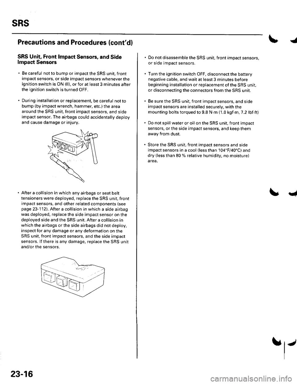
. Be careful not to bump or impact the SRS unit, front
impact sensors, or side impact sensors whenever the
ignition switch is ON (ll), or for at least 3 minules after
the ignition switch is turned OFF.
. During installation orreplacement, be careful notto
bump (by impact wrench, hammer, etc.) the area
around the SRS unit, front impact sensors, and sjde
impact sensor. The airbags could accidentally deploy
and cause damage or injury.
After a collision in which any airbags or seat belt
tensioners were deployed. replace the SRS unit, front
impact sensors, and other related components (see
page 23-112). After a collision in which a side airbag
was deployed. replace the side impact sensor on the
deployed side and the SRS unit. After a collision in
which the airbags or the side airbags did not deploy,
inspect for any damage or any deformation on the
SRS unit, front impact sensors, and the side impact
sensors. lf there is any damage, replace the SRS unit
and/or the sensors.
23-16
.j
. Do not disassemble the SRS unit, front impact sensors,
or side impact sensors.
. Turn the ignition switch OFF, disconnect the battery
negative cable, and wait at least 3 minules before
beginning installation or replacement of the SBS unit,
or disconnecting the connectors from the SRS unit.
. Be sure the SRS unit, front impact sensors, and side
impact sensors are installed securely. with the
mounting bolts torqued to 9.8 N.m (1.0 kgf.m,7.2 lbf.ft)
. Do not spill wateroroil on the SRS unit, front impact
sensors, or the side impact sensors, and keep them
away from dust.
. Store the SRS unit, front imDact sensors and side
impact sensors in a cool (less than 104"F/40'C) and
dry (less than 80 % relative humidity, no moisture)
area.
I
Page 1122 of 1139

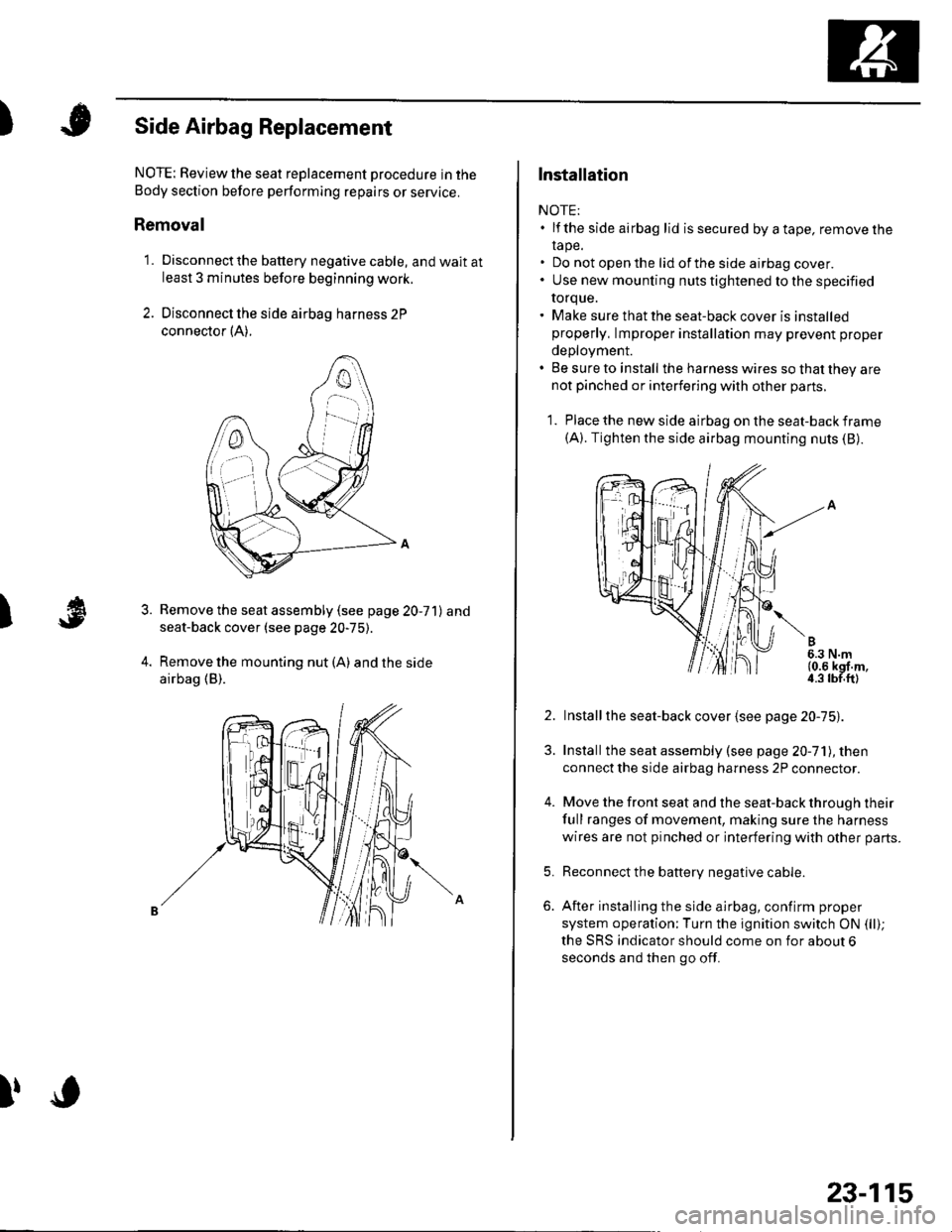
)Side Airbag Replacement
)
NOTE: Review the seat replacement pro6edure in the
Body section before pertorming repairs or service.
Removal
1. Disconnectthe battery negative cable, and wait atleast 3 minutes before beginning work.
2. Disconnect the side airbag harness 2P
connector {A).
Remove the seat assembly (see page 20-71) and
seat-back cover (see page 20-75).
Remove the mounting nut (A) and the side
airbag (B).
3.
l,o
23-115
Installation
NOTE:. lf the side airbag lid issecured byatape, removelhe
rape.. Do not open the lid of the side airbag cover.. Use new mounting nuts tightened to the specified
torque.. Make sure that the seat-back cover is installedproperly, lmproper installation may prevent proper
deployment.. Be sure to install the harness wires so that they arenot pinched or interfering with other parts.
1. Place the new side airbag on the seat-back frame(A). Tighten the side airbag mounting nuts (B).
2. Installthe seat-back cover {see page 20-75).
3. Installthe seat assembly (see page 20-71), then
connect the side airbag harness 2P connector.
4. Move the front seat and the seat-back through their
full ranges of movement, making sure the harness
wires are not pinched or interfering with other parts.
5. Reconnect the battery negative cable.
6. After installing the side airbag, confirm proper
system operation;Turn the ignition switch ON (ll);
the SRS indicator should come on for about 6
seconds and then go off.
Page 1129 of 1139

sRs
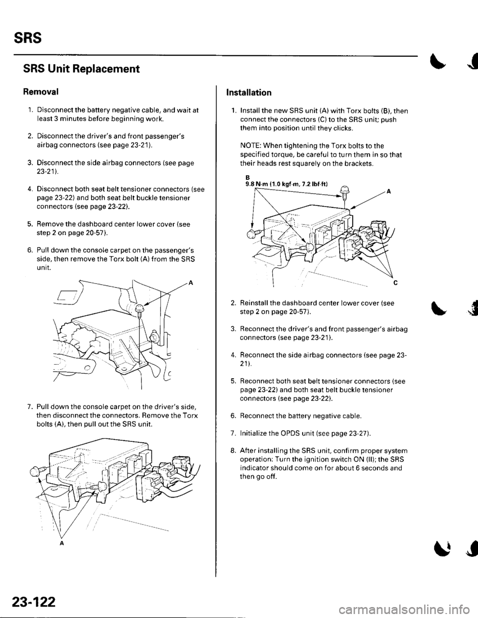
SRS Unit Replacement
Removal
'1. Disconnect the battery negative cable, and wait at
least 3 minutes before beginning work.
2. Disconnect the driver's and front passenger's
airbag connectors (see page 23-21).
3. Disconnectthe side airbag connectors (see page
23-211.
4.Disconnect both seat belt tensioner connectors (see
page 23-22) and both seat belt buckle tensioner
connectors {see page 23-221.
Remove the dashboard center lower cover (see
step 2 on page 20-57).
Pull down the console carpet on the passenger's
side, then remove the Torx bolt (A)from the SRS
unit.
7. Pull down the console carpet on the driver's side,
then disconnect the connectors. Remove the Torx
bolts (A), then pull out the SRS unit.
23-122
lnstallation
1, Installthe new SRS unit (A)with Torx bolts (B), then
connect the connectors {C) to the SRS uniu push
them into position until they clicks.
NOTE: When tightening the Torx bolts to the
specified torque, be careful to turn them in so that
their heads rest squarely on the brackets.
Reinstall the dashboard center lower cover (see
step 2 on page 20-57).
Reconnect the driver's and front passenger's airbag
connectors (see page 23-21]'.
Reconnect the side airbag connectors (see page 23-
211.
Reconnect both seat belt tensioner connectors (see
page 23-221 and both seat belt buckle tensioner
connectors (see page 23-22).
Reconnect the battery negative cable.
Initialize the OPDS unit (see page 23'27).
After installing the SRS unit, confirm proper system
operation: Turn the ignition switch ON (ll); the SRS
indicator should come on for about 6 seconds and
then go off.
4.
6.
8.
7.
9.8 N.m (1.0 kgf m, 7.2 lbf ft)