Page 346 of 1139

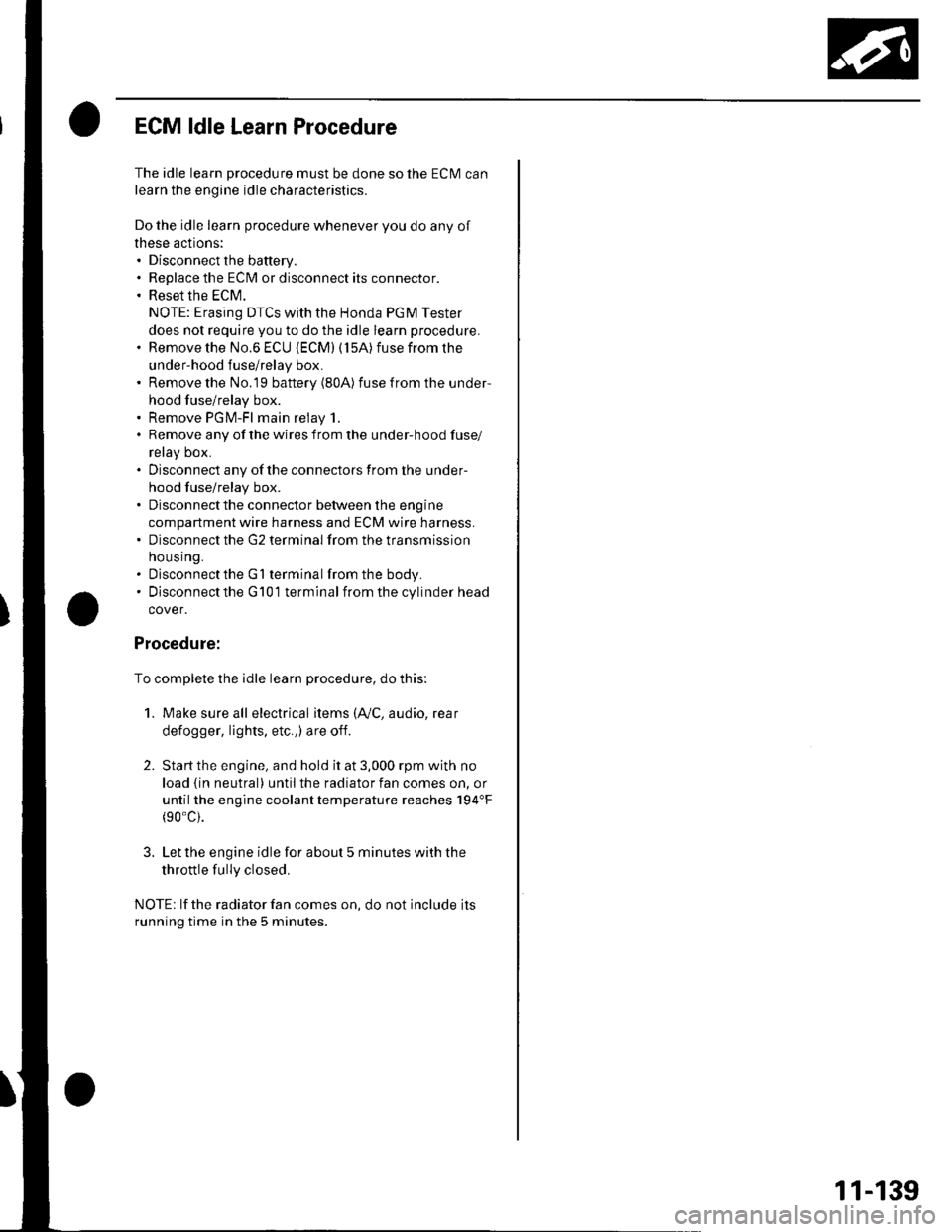
ECM ldle Learn Procedure
The idle learn procedure must be done so the ECM can
learn the engine idle characteristics.
Do the idle learn procedure whenever you do any of
these actions:. Disconnect the battery.
Replace the ECM or disconnect its connector.
Reset the ECM.
NOTE: Erasing DTCS with the Honda PGM Tester
does not require you to do the idle learn procedure.
Remove the No.6 ECU {ECM) ( 15A) fuse from the
under-hood fuse/relay box.
Remove the No.19 baftery (80A) fuse from the under-
hood fuse/relay box.
Remove PGM-FI main relay 1.
Remove any of the wires from the under-hood fuse/
retay Dox.
Disconnect any of the connectors from the under
hood fuse/relay box.
Disconnect the connector between the engine
compartment wire harness and ECM wire harness.
Disconnect the G2 terminal from the transmission
ho u srng.
Disconnectthe G'l terminal from the body.
Disconnectthe G101 terminal from the cylinder head
cover.
Procedure:
To complete the idle learn procedure, do this:
1. Make sure all electrical items (Ay'C, audio, rear
defogger, l:ghts, etc.,) are off.
2. Start the engine, and hold it at 3,000 rpm with no
load {in neutral) until the radiator fan comes on, or
until the engine coolanttemperature reaches 194"F(90'c).
3. Let the engine idle for about 5 minutes with the
throttle fully closed.
NOTE: lf the radiator fan comes on, do not include its
running time in the 5 minutes.
11-139
Page 368 of 1139

Intake Air Bypass GontrolThermalValve Test
Special Tools Required
Vacuum Pump/Gauge,0 30 in. Hg A973X-041-XXXXX
1. Stan the engine. Then let it idl€.
NOTE: The engine coolant temperature must be
below 149'F (65'C).
2. Remove the vacuum hose (A)from the intake air
duct, and connect a vacuum pump/gauge to the
nose.
3. Raise and lowerthe engine speed. and make sure
the vacuum gauge reading changes as the engine
speeo cnanges.
lf the vacuum reading does not change, check for
these problems:
. Misrouted, leaking, broken, or clogged intake air
bypass control system vacuum lines.. A cracked or damaged intake air bypass control
thermal valve.
4. Hold the engine at 3,000 rpm with no load (in
neutral) until the radiator fan comes on, then let it
id le.
5. Raise and lower the engine speed, and make sure
the vacuum gauge reading does not change as the
rpm cnanges.
lf the vacuum reading changes, check for these
proorems:
. l\4isrouted, leaking, broken, or clogged intake air
bypass control system vacuum lines.. A cracked or damaged intake air bypass control
thermal valve.
11-161
Page 371 of 1139

Intake Air System
Throttle Cable Removal/lnstallation
1. Fully open the throttle valve, then remove the
throttle cable (A) from the throttle link (B).
Remove the cable housing (C)from the cable
bracket (D).
Remove the throttle cable (A)from the accelerator
pedal (B).
2.
3.
SILICONE GREASE B(P/N 08798-9002)
(P/N 08?98-9002)
11-164
5.
Install in the reverse order of removal.
After installing, start the engine. Hold the engine at
3,000 rpm with no load (in neutral) untilthe radiator
fan comes on, then let it idle.
Hold the cable, removing all slack from it.
Set the locknut on the cable bracket {A).Turn the adjusting nut (B) so that its free play is
0 mm.
The should beno crearance.
Remove the cable from the cable bracket (A). Set
the adjusting nut on the other side of the throttle
bracket, then tighten the locknut {C}.
With the cable properly adjusted, check the throttle
valve to be sure it opens fully when you push the
accelerator pedal to the floor. Also check the
throttle valve to be sure it returns to the idle
position whenever you release the accelerator
Deoat.
7.
!
8.
9.
('1.0 kgf.m,7.2 tbf.ftl
Page 374 of 1139

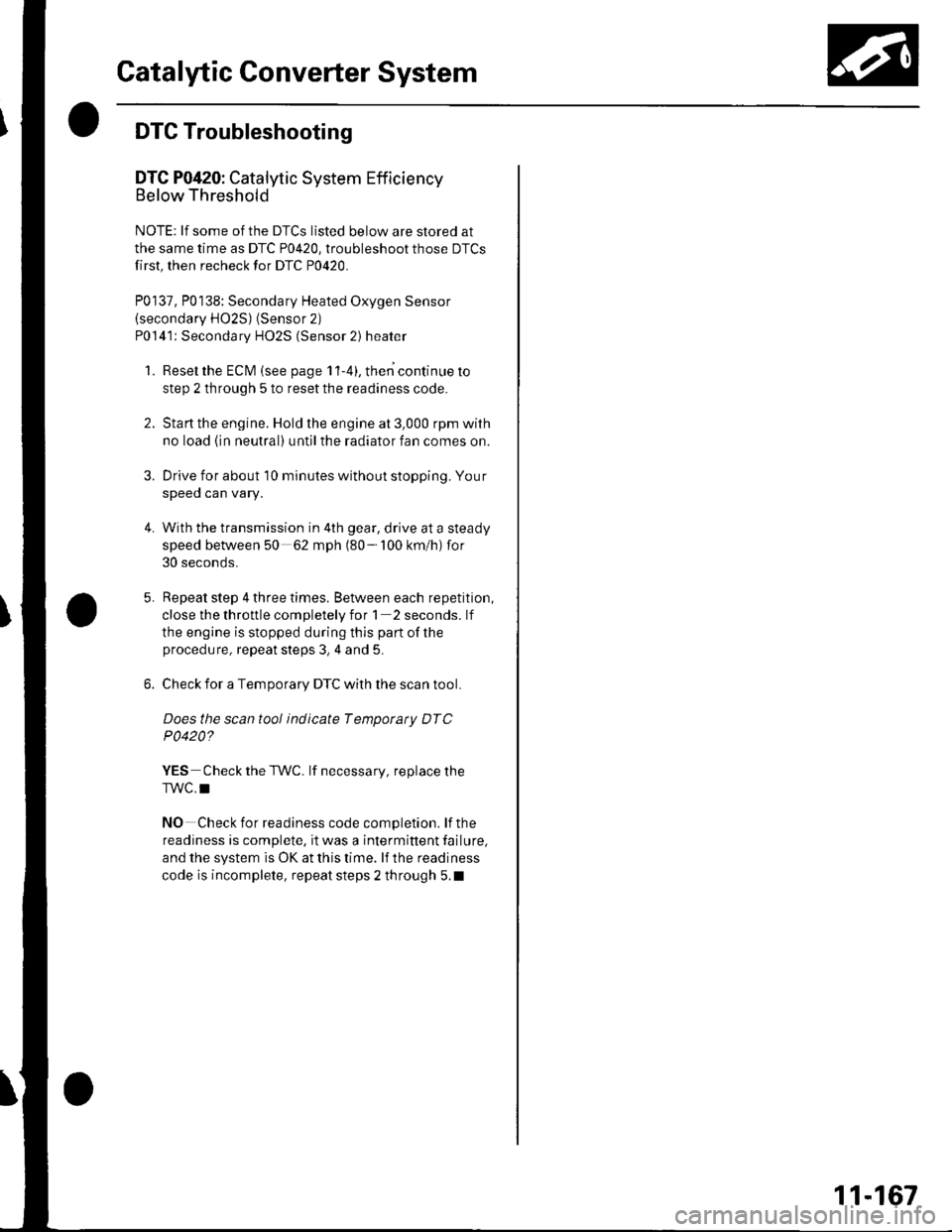
Catalytic Converter System
DTC Troubleshooting
DTC P0420: Catalytic System Efficiency
Below Threshold
NOTE: lf some of the DTCS listed below are stored at
the same time as DTC P0420, troubleshoot those DTCS
first, then recheck for DTC P0420.
P0137, P0138: Secondary Heated Oxygen Sensor(secondary HO2S) (Sensor 2)
P0141: Secondary HO2S (Sensor 2) heater
1. Reset the ECM {see page 1'l-4}, then continue to
step 2 through 5 to reset the readiness code.
2. Start the engine. Hold the engine at 3,000 rpm with
no load (in neutral) untilthe radiator fan comes on.
Drive for about l0 minutes without stopping. Your
speeo can vary.
With the transmission in 4th gear, drive at a steady
speed between 50 62 mph (80-'100 km/h) for
30 seconds.
Repeat step 4 three times. Between each repetition,
close the throttle completely for 1 2 seconds. lf
the engine is stopped during this part of the
procedure, repeat steps 3, 4 and 5.
Check for a Temporary DTC with the scan tool.
Does the scan tool indicate Temporaty DTC
P0420?
YES Check the TWC. lf necessary, replace the
TWC.I
NO Check for readiness code completion. lfthe
readiness is complete, it was a interminent failure,
and the system is OK at this time. lf the readiness
code is incomplete, repeat steps 2 through 5.1
4.
11-167
Page 375 of 1139
PCV System
DTC Troubleshooting
DTC P1505: PCV Air Leakage
1. Reset the ECM (see page 11-4).
2. Start the engine. Hold the engine at 3,000 rpm with
no load (in neutral) until the radiator fan comes on
3. Let the engine idle tor al least 40 seconds with the
throttle fully closed.
4. Check for a DTC P1505 with the scan tool
ls DTC P1505 indicated?
YES-Check these parts for vacuum leaks l
. PCV valve. PCV hose. EVAP canister purge valve
. Throttle body. Brake booster hose
NO - Intermittent failure, system is OK at this
time.l
11-168
Page 773 of 1139

21-2
z t-'5
z t-o
z t-o
21-8
21-9
21-10
21-11
21-14
z t- to
HVAC (Heating, Ventilation, and Air Gonditioningl
Heating and Air Conditioning
SpecialTools
Comoonent Location lndex ........
A/C Service Tios and
Precautions
A,/C Refrigerant Oil
ReDlacement
General Troubleshooting
lnformation
DTC Troubleshooting Index .......
Symptom Troubleshooting
1ndex..............
System Description .....................
Circuit Diagram
DTC Troubleshooting ..................
Recirculation Control Motor
CircuitTroubleshooting .......... 21-25
Heater Control Power and Ground
Circuits Troubleshooting ........ 21-27
Condenser Fan Circuit
Troubleshooting ...................... 21-28
Radiator and Condenser Fans
Common Circuit
Troubfeshooting ...................... 21-29
Compressor Clutch Circuit
Troubleshooting ...................... 21-30
A,/C Pressure Switch Circuit
Troubleshooting ...................... 21-32
Air Mix Control Motor
Test and Reolacement ............. 21-34
Mode Control Motor
Test and Replacement ............. 21-35
Recirculation Control Motor
Test and Reolacement ............. 21-36
Evaporator Temperature Sensor
Reolacement and Test ............. 21-31
Power Transistor Test ................. 21 -38
Heater Control Panel and
Push Switch Assemblv
Removal and Installation ........ 21-38
Dust and Pollen Filter
Reolacement ..21-39
Blower Unit Removal and
lnstallation ...... 21-39
Blower Unit Comoonents
ReDlacement ............................ 21-41
Evaporator Core
Reolacement ..21-42*Heater Unit/Core
ReDlacement ..21-43
Heater Valve Cable
Adjustment .....21-46
CompressorReplacement .......... 21-47
Comoressor Clutch Check .......... 21-48
Comoressor Clutch Overhaul ..... 21-49
Compressor Thermal Protector
Reo1acement ............................ 21-51
Comoressor Relief Valve
Reolacement ............................ 21-51
Condenser Reolacement ............ 21-52
Refrigerant Recovery .................. 21-53
System Evacuation ...................... 21-54
System CharginS ......................... 21-55
Refrigerant LeakTest .................. 21-56
A,/C Svstem Tests ........................ 21-57
Page 776 of 1139
Heating and Air Conditioning
Component Location Index (cont'dl
CONDENSER FANTest, page 22-51
RADIATOR FAN RELAYTest, page 22-51
Tesl, page 22-51CLUTCH RELAY
MOTOR RELAYTest, page 22-5I
UNDER.HOOD FUSE/RELAY BOX
... A/C PRESSURE SWITCH
RADIATOR FAN
\
.\
-
'-t t_]]l
/l I T I --::--
l- -l -
CONOENSER FAN
21-4
Page 782 of 1139

Heating and Air Conditioning
{
a
a
SvmptomDiagnostic procedureAlso check for
Recirculation control doors do not
change between Fresh and Recirculate
Recirculation Control Motor
Circuit Troubleshooting (see page
21 251
Cleanliness and tightness of all
connectors
Both heater and Ay'C do not workHeater Control Power and Ground
Circuits Troubleshooting (see
page 21-27)
Blown fuse No. '14 (10A) in the
under-dash fuse/relay box
Poor ground at G501
Cleanliness and tightness of all
conneclors
Condenser fan does not run at all (but
radiator fan runs with the Ay'C on)
Condenser Fan Circuit
Troubleshooting {see page 21-28)
. Poor ground at G301. Cleanliness and tightness of all
connectors
Both fans do not run with the A,/C onRadiator and Condenser Fans
Common Circuit Troubleshooting
(see page 21-29)
Blown fuse No. 1 (20A) and No.4
(20A) in the under-hood fuse/relay
box
Poor ground at G30l
Cleanliness and tightness of all
connectors
Compressor clutch does not engage(both fans run with A,/C on)
Compressor Clutch Circuit
Troubleshootinq (see Daqe 21-30)
Cleanliness and tightness of all
connectors
A/C system does not come on (both
fans and compressor)
Ay'C Pressure Switch Circuit
Troubleshooting (see page 21-32)
Blown fuse No. 1 (20A) and No. 4
(20A) in the under-hood fuse/relay
box
Poor ground at G301
Cleanliness and tightness of all
connectors
\Symptom Troubleshooting Index
\
21-10
!