Page 8 of 1139
General Information
Warning/Caution Label Locations (cont'dl
SRS WARNINGLABEL
SERVICE INFORMATION LABEL(Undor-hood Emission ControlInformation lab€l) and ENGINECOOLANT INFORMATION
RADIATORCAP CAUTION
BATTERYCAUTION
1-6
t
TIRE INFORMATION
c
Page 18 of 1139
ItemMeasulementOualificationStandard or New Service LimitFuel pressure
regulator
Pressure with fuel pressure gauge
connected
320-370 kPa 13.3-'3.8 kgtcm', 47 52psi)
FueltankCapacity50 4 (13.2 US galiEngine idleldle speed with headlights and radiator
fan off
Neutral750 50 rpm
Fast idleNeutral1,600150 rpm
Standards and Service Limits
Fuel and Emissionsf
.\
ra
Clutch
ItemMea3urem€nlOualificationSlandard or NewService LimitClutch pedalHeight from the floor193 mm (7.60 in.)Stroke130 140 mm 15.1 5.5in.)
10 16 mm (0.39 0.63 in.)Disengagement height from the floor1'15 mm (4.53 in.) min.Bunout on clutch mating surface0.05 mm 10.002 in.) max.0.15 mm (0.006 in.)Clutch discBivet head depth1.65 2.25 mm (0.065 0.089 in.)0.7 mm {0.03 in.)Ihickness8.3 8.9 mm (0.33 0.35 in.)6.0 mm (0.24 in.)Pressure plateWarpage0.03 mm (0.001 in.)max.0.15 mm (0.001 in.)Height of diaphragm spring fingersMeasured with
specialtool and
feeler gauge
0.6 mm (0.02 in.) max.0.8 mm (0-03 in.)
2-6
\
Page 52 of 1139

lgnition Timing Inspection
1.
4.
5.
Connect the Honda PGM Tester to the data link
connector (DTC), and check for DTC'S. lf a DTC is
present, diagnose and repair the cause before
inspecting the ignition timing.
Startthe engine. Hold the engine at 3,000 rpm with
no load (in Neutral) until the radiator fan comes on,
then let it idle.
Check the idle speed (see page 11-138).
Follow the tester's prompts in the "SCS" menu
{see the tester operator's manual),
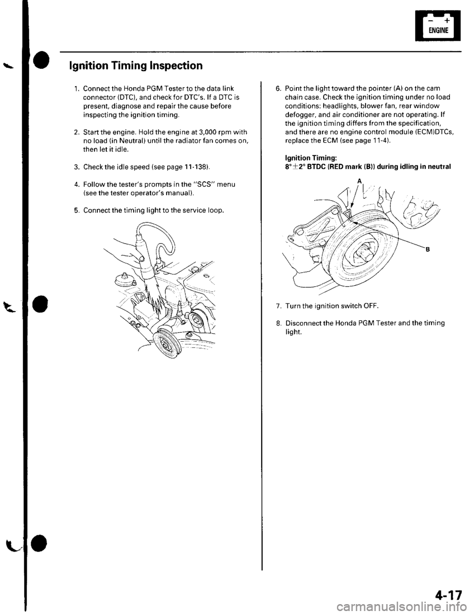
Connect the timing light to the service loop.
o
6. Point the light toward the pointer (A) on the cam
chain case. Check the ignition timing under no load
conditions: headlights, blower fan. rear window
defogger, and air conditioner are not operaling. lf
the ignition timing differs from the specification,
and there are no engine control module {ECM)DTcs,
replace the ECM (see page 11-4)
lgnition Timing:
8"+2" BTDC {RED mark {B)) during idling in neutral
A
7. Turn the ignition switch OFF.
Disconnectthe Honda PGM Tester and thetiming
light.
4-17
Page 59 of 1139

Gharging System
Charging Circuit Troubleshooting (cont'd)
6. Start the engine. Hold the engine at 3,000 rpm with
no load (in Neutral) until the radiator fan comes on,
then let it idle.
7. Raise the engine speed to 2,000 rpm, and hold it
there.
8. Turn the headlights (high beam) on, and measure
voltage at the under-hood fuse/relay box terminal.
ls the voltage between 13.9 and 15.1 v?
YES-Go to step 9.
NO Repair or replace the alternator components
(see page 4-30).1
9. Read the amperage at '13.5 V.
NOTE: Adjust the voltage by turning the blower
motor, rear window defogger, brake lights. etc. ON.
ls the amperage 604 ot morc?
YES-Alternator/regulator operation is OK. I
NO Repair or replace the alternator components(see page 4-30).1
4-24
\,
Alternator Control System Test
NOTE: After troubleshooting, perform the engine
control module (ECM) idle learn procedure (see page
11-139).
1 . Check for proper operation of the electrical load
detector (ELD) by checking the malfunction
indicator lamp (MlL) (see page 1 l-3). lf a DTC is
present, diagnose and repair the cause before
continuing with this test.
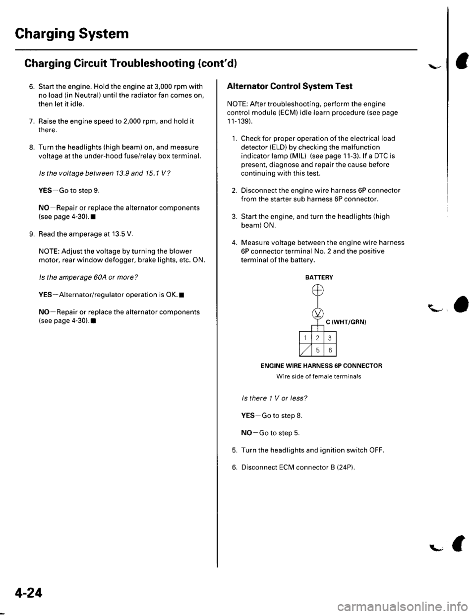
2. Disconnect the engine wire harness 6P connector
from the starter sub harness 6P connector.
3. Start the engine, and turn the headlights (high
beam) ON,
4. Measure voltage between the engine wire harness
6P connector terminal No. 2 and the positive
terminal of lhe battery.
C {WHT/GRN)
ENGINE WIRE HARNESS 6P CONNECTOR
Wire side of female terminals
ls there 1 V or less?
YES Go to step 8.
NO-Go to step 5.
Turn the headlights and ignition switch OFF.
Disconnect ECM connector B (24P).
5.
6.
BATTERY
Page 85 of 1139
18.
19.
Remove the drive belt (see page 4-26).
Remove the lvC line mounting bolt.
20. Remove the radiator cap.
21. Raise the hoist to full height.
22. Remove the front tires/wheels.
23. Remove the splash shield.
o@
24. Loosen the drain plug in the radiatorto drain the
engine coolant (see page 10-6).
25. Drain the transmission fluid (see page 13'3).
26. Drain the engine oil {see page 8-5).
27. Disconnect the stabilizer links (see page 18-18).
28. Disconnect the suspension lower arm ball joints
(see step 3 on page 18-19).
29. Remove the driveshafts {see page 16-3). Coat all
precision finished surfaces with clean engine oil.
Tie plastic bags over the driveshaft ends.
30. Disconnect the air fuel ratio {4,/F) sensor connector
(A) and secondary heated oxygen sensor
(secondary HO2S) connector (B), then remove the
three way catalytic converter {TWC) assembly {C).
31. Remove the lower hose.
(cont'd)
5-5
Page 86 of 1139
Engine Assembly
Engine Removal (cont'd)
32. Lower the hoist.
33. Remove the upper hose (A)and heater hoses (B).
34. Bemove the radiator (see page 10-10).
35. Attach the chain hoist to the engine as shown.
5-6
36. Remove the transmission mount bracket support
bolt and nuts.
37. Remove the upper bracket mounting bolt and nut.
(.g
\a
Page 91 of 1139
7. Loosely tighten the front mount bracket mounting
bolt.
Lower the hoist.
Tighten the upper bracket mounting bolt and nut.
8.
9.
10. Tighten the transmission mount bracket support
bolt and nuts.
12 x 1.25 mm54 N m {5.5 kgt m, 40 lbf.ft}
Raise the hoist to full height.
Tighten the front engine mount bracket mounting
bolt.
'l '1.
't2.
12 x 1.25 rnrn64 N.m {6.5 kgf.m,47 tbt.ftl
13. Lower the hoist.
14. Remove the chain hoist from the engine.
'15. Installthe radiator (see page 10-10).
'16. Raise the hoist to full height.
17. Install a new set ring on the end of each driveshaft,
then install the driveshafts. Make sure each ring"clicks" into place in the differential and
intermediate shaft.
(cont'd)
:l
5-11
Page 92 of 1139
Engine Assembly
18.
Engine Installation {cont'dl
10 x 1.25 mm33 N.m {3.i1kgf.m,25 tbt.ftl
19.
20.
Connect the suspension lower arm ball joints (see
step 6 on page 18-19).
Connect the stabilizer links (see page 18-18).
Install the three way catalytic converter (TWC)
assembly (A); use new gaskets (B) and new self-
locking nuts {C).
\D
21.
-d
,ry6\
8 x 1.25 mm22N.m |.2.2kgl m,16 tbt.ft)
Connect the air fuel ratio (4,/F) sensor connector (D)
and secondary heated oxygen sensor (secondary
HO2S) connector (E).
Install the lower radiator hose.
5-12
va
23. Installthe splash shield.
24.
25.
26.
Lower the hoist.
Installthe drive belt.
Installthe A,/C line mounting bolt.
6 x '!.0 mm9.8 N.m (1.0 kgf.m,7.2 tbt.ftl
. -t- --�- --�--r