Page 17 of 1139

L
v
2-5
oi
Lubrication
a
a
nqlne
|temMeasurementOualificalionStanderd or New Service Limil
Engine oilCapacity5.3 0 (5.6 US qt)for engine overhaul
4.2 0 (4.4 US qt) for oil change, including filter
4.0 0 (4.2 US qt)for oil change, without filter
Oilpumplnner-to outer rotor clearance0.02 0.16 mm {0.001 0.006 in.)0.20 mm (0.008 in.)
Pump housing to outer rotor
clearance
0-15 0.21 mm {0.006-0.008 in.)0.23 mm (0.009 in.)
Pump housing-to-rotor axial
clearance
0.02 0.07 mm (0.001 0.003 in.)0.12 mm (0.005 in.)
Balancer shafts, journal diameterNo. 1 journal, front
shaft
19.938 19.950 mm 10.7850 0.7854 in.)19.92 mm (0.784 in.)
No 1 journal, rear shaft23.938 23.950 mm (0.9424 0.9429 in.)23.92 mm (0.942 in.)
No. 2 journal, front and
rear shaft
32.949 32.961 mm 11.2912 1.2911 in.l32.93 mm (1.296 in.)
Ealancer shafts, journal taper0.005 rnm (0.0002 in.) max.
Balancer shafts, end playFront0.070 0.135 mm (0.0028 0.0053 in.)0.15 mm (0.006 in.)
Rear0.070 0.135 mm (0.0028 0.0053 in.)0.15 mm (0.006 in.)
Balancer shatts, shaft-to'bear;ng
clearance
No. 1 iournal, front
shaft
0.050 0.082 mm (0.0020 0.0032 in.)0.10 mm (0.004 in.)
No. 1 Journal, rear shaft0.050 0.082 mm (0.0020 0.0032 in.) 0.10 mm (0.004 in.i
No. 2 journal, front and
rear shafl
0.060 -0.120 mm (0.0024 0.0047 in.) 0.15 mm (0.006 in.)
Balancer shaft bearings, LD.No. 1 journal, front
shaft
No. 1 iournal, rear shaft
20.000 20.020 mm (0.1814 0.7442 in.l
Z+.OOO ZI.OZO m- tOSa+e- OSa57 ir'.)
20.03 mm (0.789 in.)
24.03 mm (0.946 in.)
No. 2 journal, front and
rear shaft
33.021 33.069 mm (1.3000 1.3019 in.)33.09 mm {1.303 in.)
Reliefvalve, oil pressure with oil
temperature at 176'F (80"C)
At idle70 kPa (0.7 kq?cm , 10 psr) min.
At 3,000 rpm300 kPa {3.1 ksf/cm',44 psi)min.
Standard or New Service Limit
6.7 L (7.1 USCoolant capacity {includes engine,
heater, hoses, and reservoir)
0.53 L (0.56 US
93 123 kPa (0.95 1.25 kqtcm , 14 18 psi)'t69 176'F (76 80'C)Thermostat OPeningtemPerature
8.0 mm {0.31 in.) min.
Turns OFF Subtract 5 15'F (3 8"C)from actual ON
Page 86 of 1139
Engine Assembly
Engine Removal (cont'd)
32. Lower the hoist.
33. Remove the upper hose (A)and heater hoses (B).
34. Bemove the radiator (see page 10-10).
35. Attach the chain hoist to the engine as shown.
5-6
36. Remove the transmission mount bracket support
bolt and nuts.
37. Remove the upper bracket mounting bolt and nut.
(.g
\a
Page 93 of 1139
27. lnstallthe upper radiator hose {A) and heater hoses(B).
Push the engine control module (ECM) connectors
through the bulkhead, then installthe grommet (A).
29. Installthe harness clamps (B).
30. Connect the ECI\4 connectors (A) and main wire
harness connector (B).
Install the throttle cable (see page 11-164), then
adjustthe cable {see page 11-'163).
Installthe cruise control cable (see page 4-44), then
adjust the cable (see page 4-45),
Install the brake booster vacuum hose (A) and the
evaporative emission (EVAP) canister hose (B).
34. Installthe fuel line (see page 11-150).
31.
32.
33.
(cont'd)
5-13
Page 95 of 1139

40. Install the air cleaner housinq.
6x1.0mm12 N m (1.2 kgf.m,8.7 lbt.ft)
Install the air cleaner housing cover (A) and
connect the intake air temperature (lAT) sensor
connector (B),
42. Installthe breather hose (C) and vacuum hose 1D).
41.
43. Installthe intake manifold cover.
6x1.0mm12Nm11.2kgf.m.8.7 tbf.ft)
Installthe battery. Clean the battery posts and
cable terminals with sandpaper, then assemble
them and apply grease to prevent corrosion.
Check that the transmission shifts into gear
smoothly.
Inspect for fuel leaks. Turn the ignition switch ON(ll) {do not operate the starter) so that the fuel pump
runs for about 2 seconds and pressurizes the fuel
line. Repeat this operation two or three times, then
check for fuel leakage at any point in the fuel line.
Refillthe engine with engine oil (see page 8-5).
Refill the transmission with fluid (see page 13-3).
Refill the radiator with engine coolant, and bleed
air from the cooling system with the heater valve
open (see page 10-6).
Perform the engine control module (ECM) idle learnprocedure (see page 11-139).
Inspect the idle speed (see page 1 1-138).
Inspect the ignition timing (see page 4-17).
Check the wheel alignment {see page 18-4).
Enter the anti-theft code for the radio, then enter
the customer's radio station presets.
Set the clock.
YE
44.
41.
]tE
46.
48.
49.
52.
53.
54.
50.
51.
55.
5-15
Page 118 of 1139

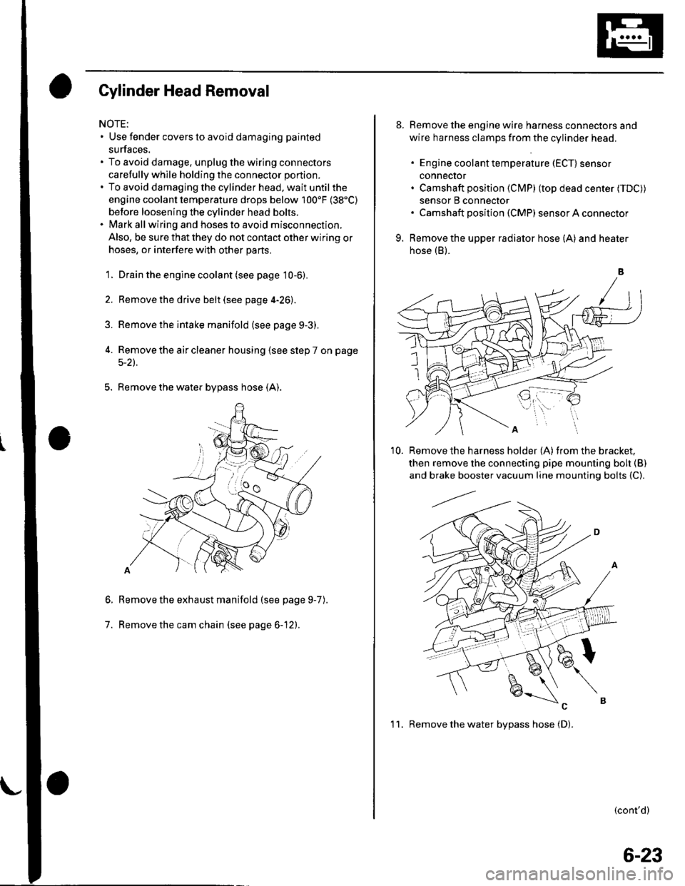
Gylinder Head Removal
NOTE:. Use fender covers to avoid damaging painted
surfaces.
To avoid damage, unplug the wiring connectors
carefully whlle holding the connector portion.
To avoid damaging the cylinder head, wait until the
engine coolant temperature drops below 100'F (38"C)
betore loosening the cylinder head bolts.
Mark all wiring and hoses to avoid misconnection.
Also, be sure that they do not contact other wiring or
hoses, or interfere with other parts.
'1.
2.
3.
Drain the engine coolant (see page 10-6).
Remove the drive belt (see page 4-26).
Remove the intake manifold {see page 9-3).
Remove the air cleaner housing (see step 7 on page
5-2t.
5. Remove the water bypass hose (A).
Remove the exhaust manifold (see page 9-7
Remove the cam chain (see page 6-12).
6.
7.
).
8. Remove the engine wire harness connectors and
wire harness clamps from the cylinder head.
. Engine coolant temperature (ECT) sensor
conneclor. Camshaft position (Cl\4P) (top dead center (TDC))
sensor B connector. Camshaft posilion (CMP) sensor A connector
9. Remove the upper radiator hose (A) and heater
hose (B).
'10. Remove the harness holder (A)from the bracket,
then remove the connecting pipe mounting boh {B)
and brake booster vacuum line mounting bolts {C).
(cont'd)
1 1. Remove the water bvpass hose (D).
6-23
Page 135 of 1139

Cylinder Head
8.
Cylinder Head lnstallation (cont'd)
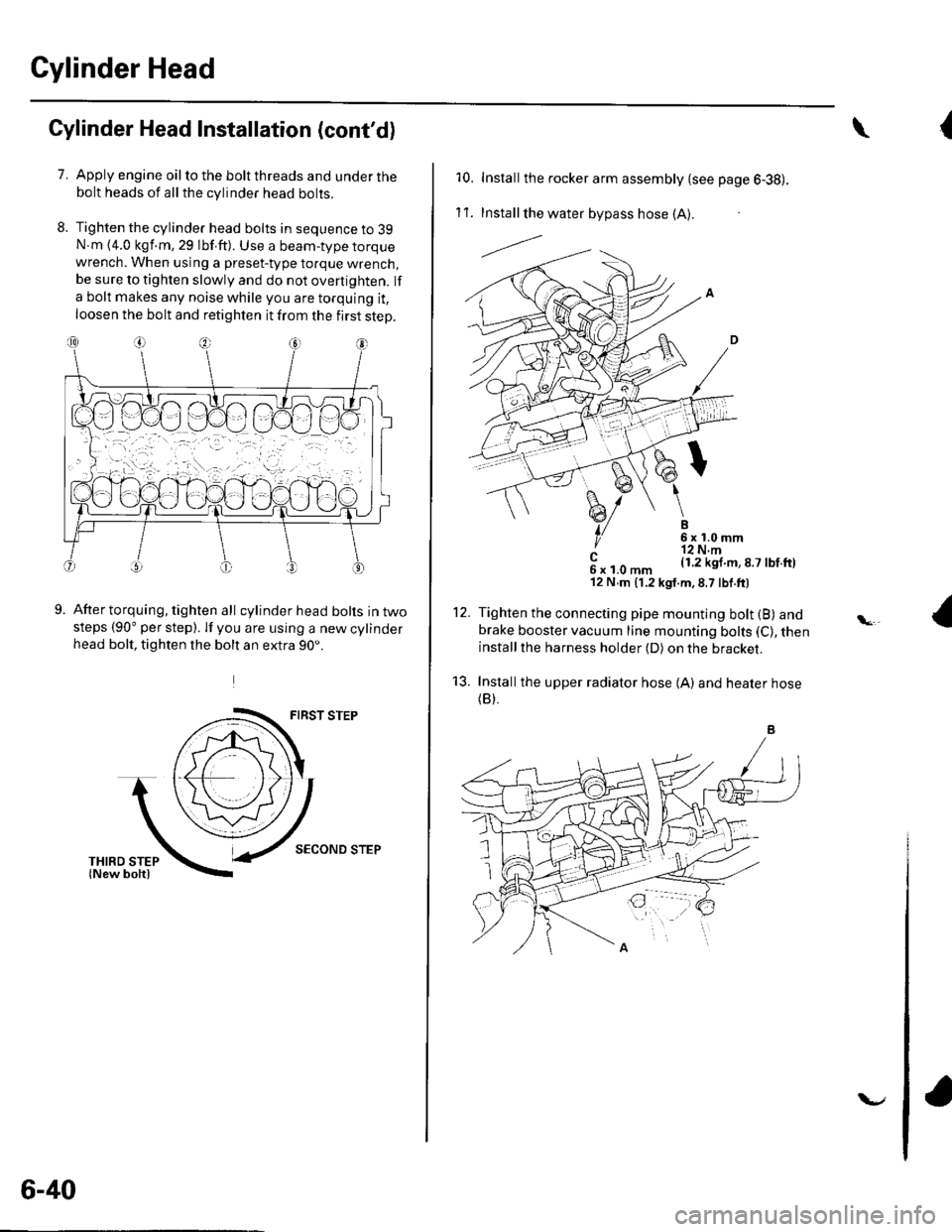
7.Apply engine oil to the bolt threads and under thebolt heads of all the cylinder head bolts.
Tighten the cylinder head bolts in sequence to 39N.m {4.0 kgf.m, 29 lbf.ft). Use a beam-type torquewrench. When using a preset-type torque wrench,be sure to tighten slowly and do not overtighten. lf
a bolt makes any noise while you are torquing it,
loosen the bolt and retighten it from the first step.
9.After torquing, tighten all cylinder head bolts in twosteps (90" per step). lf you are using a new cylinderhead bolt, tighten the bolt an extra 90..
FIRST STEP
SECOND STEP
6-40
v
{\
10. Installthe rocker arm assembly {see page 6-38).
1't .Install the water bypass hose (A).
---l.-.
B6x1.0mm'r2 N.m(1.2 kgl.m,8.7 lbf.ftl
12.
't3.
c6xl.0mm'12 N,m (1.2 kgt.m,8.7 lbf.ft)
Tighten the connecting pipe mounting bolt (B) andbrake booster vacuum line mounting bolts (C), theninstallthe harness holder (D) on the bracket.
Installthe upper radiator hose {A) and heater hose(B).
Page 136 of 1139

14. Installthe water bvpass hose.
15. Installthe air cleaner housing (see step 37 on page
5-15).
16. Installthe intake manifold (see page 9-5).
17. Installthe exhaust manifold (see page 9-7).
'18. Installthe cam chain (see page 6-15).
19. Adjust the valve clearance (seepage6-9).
20. Installthe drive belt (see page 4-26).
21. Clean the battery posts and cable terminals with
sandpaper, then assemble them and apply grease
to prevent corrosion.
22. After installation, checkthatall tubes, hosesand
connectors are installed correctly.
23. Inspectforfuel leaks. Turn the ignition switch ON
{ll) {do not operate the starter) so that the fuel pump
runs for about 2 seconds and pressurizes the fuel
line. Repeat thls operation two or three times, then
check for fuel leakage at any point in the fuel line.
24. Refillthe radiator with engine coolant, and bleed
air from the cooling system with the heater valve
open (see page 10-6).
25. Inspect the idle speed (see page 11-'138).
26. Inspect the ignition timing (see page 4-17).
Gylinder Head Cover lnstallation
1. Thoroughly clean the head cover gasket and the
groove.
2. Installthe head cover gasket (A) in the groove of
the cylinder head cover (B).
Check that the mating surfaces are clean and dry.
Apply liquid gasket. P/N 08718-0009, on the chain
case and the No.5 rocker shaft holder mating areas.
NOTE: Do not install the parts if 5 minutes or more
have elapsed since applying liquid gasket. Instead,
reapply liquid gasket after removing old residue.
(cont'd)
6-41
Page 188 of 1139
lntake Manifold and Exhaust System
Intake Manifold Removal and Installation (cont'd)
9. lnstallthe air cleaner housing cover (A), and
connect the IAT sensor connector (B).
BC
Installthe breather hose (C).
lnstallthe EVAP canister hose (A), brake booster
vacuum hose (B), and vacuum hoses {C).
10.
11.
9-6
\
12. Installthe intake manifold cover.
6x1.0mm12 N.ml.1.2k91.m,8.7 tbf.ftl
Clean up any spilled engine coolant.
After installation, check that all tubes, hoses, and
connectors are installed correctly.
Inspect for fuel leaks. Turn the ignition switch ON
(ll) (do not operate the starter) so that the fuel pump
runs for about 2 seconds and pressurizes the fuel
line. Repeat this operation two or three times, then
check for fuel leakage at any point in the fuel line.
Refill the radiator with engine coolant, and bleed
air from the cooling system with the heater valve
open (see page 10-6).
to.
\-