2002 HONDA CIVIC 11-4
[x] Cancel search: 11-4Page 1090 of 1139

I
I
8. Read the DTC.
ls DTC 11-3 indicated?
YES-Go to step 9.
NO*Shon to another wire in the driver's side
airbag inflator; replace the driver's side airbag (see
page 23-115).I
9. Turn the ignition switch OFF. Disconnect the
battery negative cable. and wait for 3 minutes.
10. Disconnectthe front passenger's side airbag 2P
connector (see step 4 on page 23-21) and both seat
belt buckle tensioner 4P connectors (see step 6 on
page 23-22l,.
11. Disconnect the special tool from the floor wire
harness 2P connector.
12. Disconnect SRS unit connector B {18P)from the
SRS unit {see step 7 on page 23-221.
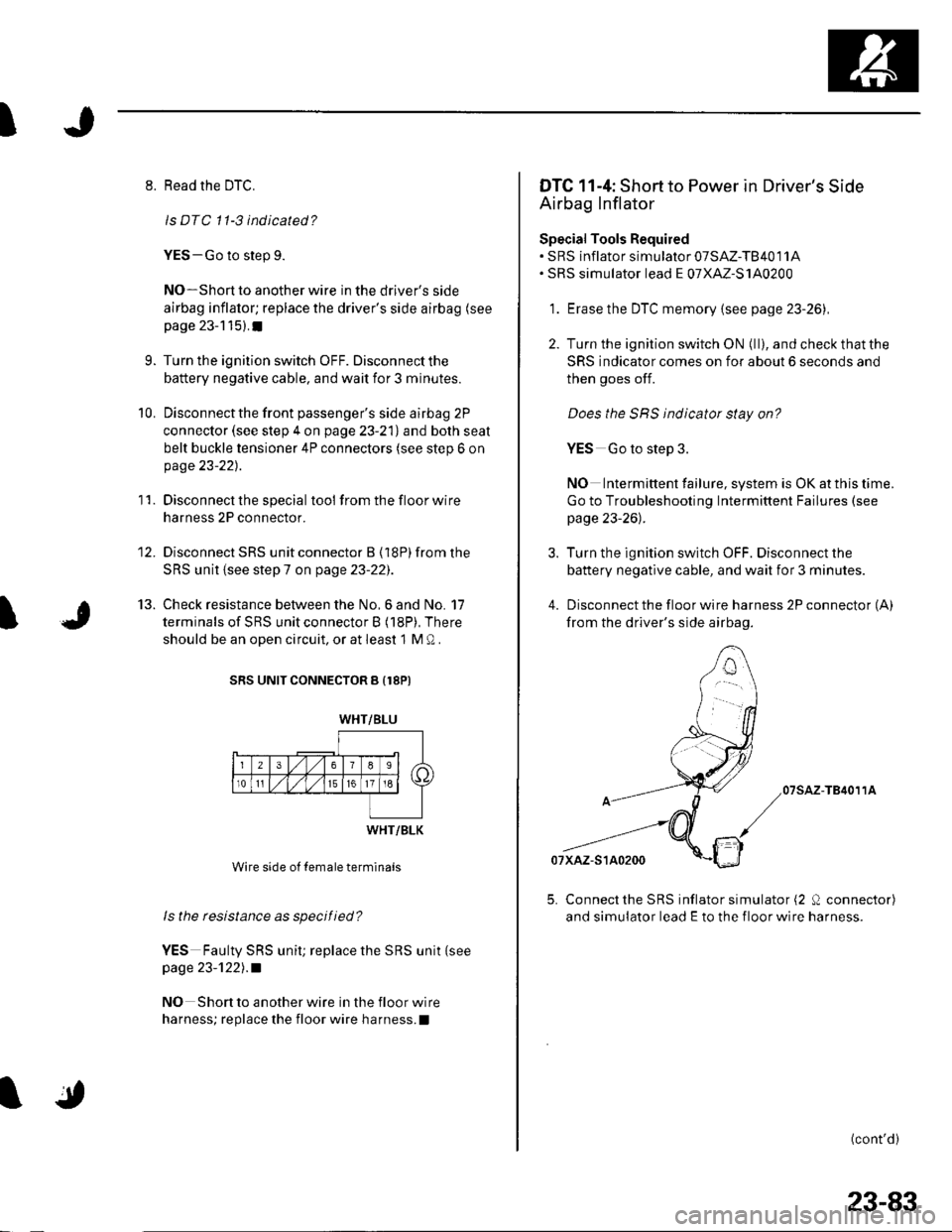
13. Check resistance between the No.6 and No. 17
terminals of SRS unit connector B (18P), There
should be an open circuit, or at least 1 M 0.
SRS UNIT CONNECTOR B {18PI
Wire side of female terminals
ls the resistance as specified?
YES Faulty SRS unit; replace the SRS unit {seepage 23-'t221 .a
NO Shon to another wire in the floor wire
harness; replace the floor wire ha rness.I
WHT/BLU
WHT/BLK
DTG 11-4: Short to Power in Driver's Side
Airbag Inflator
Special Tools Required. SRS inflator simulator 07SAZ-T84011A. SRS simulator lead E o7XAZ-S140200
1. Erase the DTC memory {see page 23-261.
2. Turn the ignition switch ON (ll), and check thatthe
SRS indicator comes on for about 6 seconds and
then goes off.
Does the SBS indicator stay on?
YES Go to step 3.
NO Intermittent failure, system is OK at this time.
Go to Troubleshooting Intermittent Failures (see
page 23-26l,.
3. Turn the ignition switch OFF. Disconnect the
battery negative cable, and wait for 3 minutes.
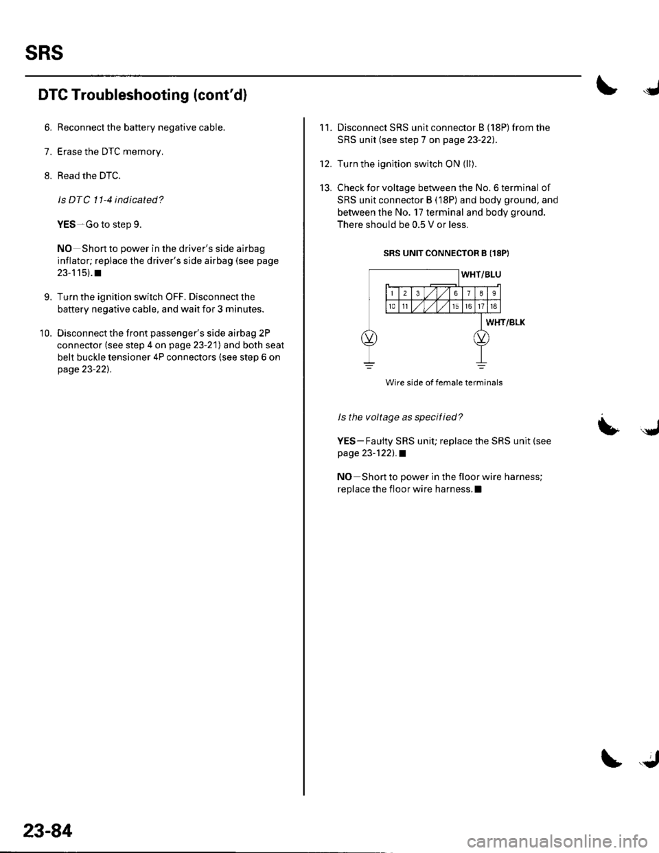
4. Disconnect the floor wire harness 2P connector (A)
from the driver's side airbag.
07sAz-TB4011A
5. Connect the SRS inflator simulator (2 0 connector)
and simulator lead E to the floor wire harness.
(cont'd)
23-83
Page 1091 of 1139

sRs
DTC Troubleshooting (cont'd)
6. Reconnect the battery negative cable.
7. Erase the DTC memory,
8. Read the DTC.
Is DTC 11-4 indicated?
YES-Go to step 9.
NO Short to power in the driver's side airbag
inflator; replace the driver's side airbag (see page
23-115).t
Turn the ignition swilch OFF. Disconnect the
battery negative cable, and wait for 3 minutes.
Disconnect the front passenger's side airbag 2P
connector (see step 4 on page 23-21) and both seat
belt buckle tensioner 4P connectors (see steD 6 on
page 23-221.
9.
'10.
23-84
\.J
11.Disconnect SRS unit connector B (18P) from the
SRS unit (see step 7 on page 23-22l,.
Turn the ignltion switch ON (ll).
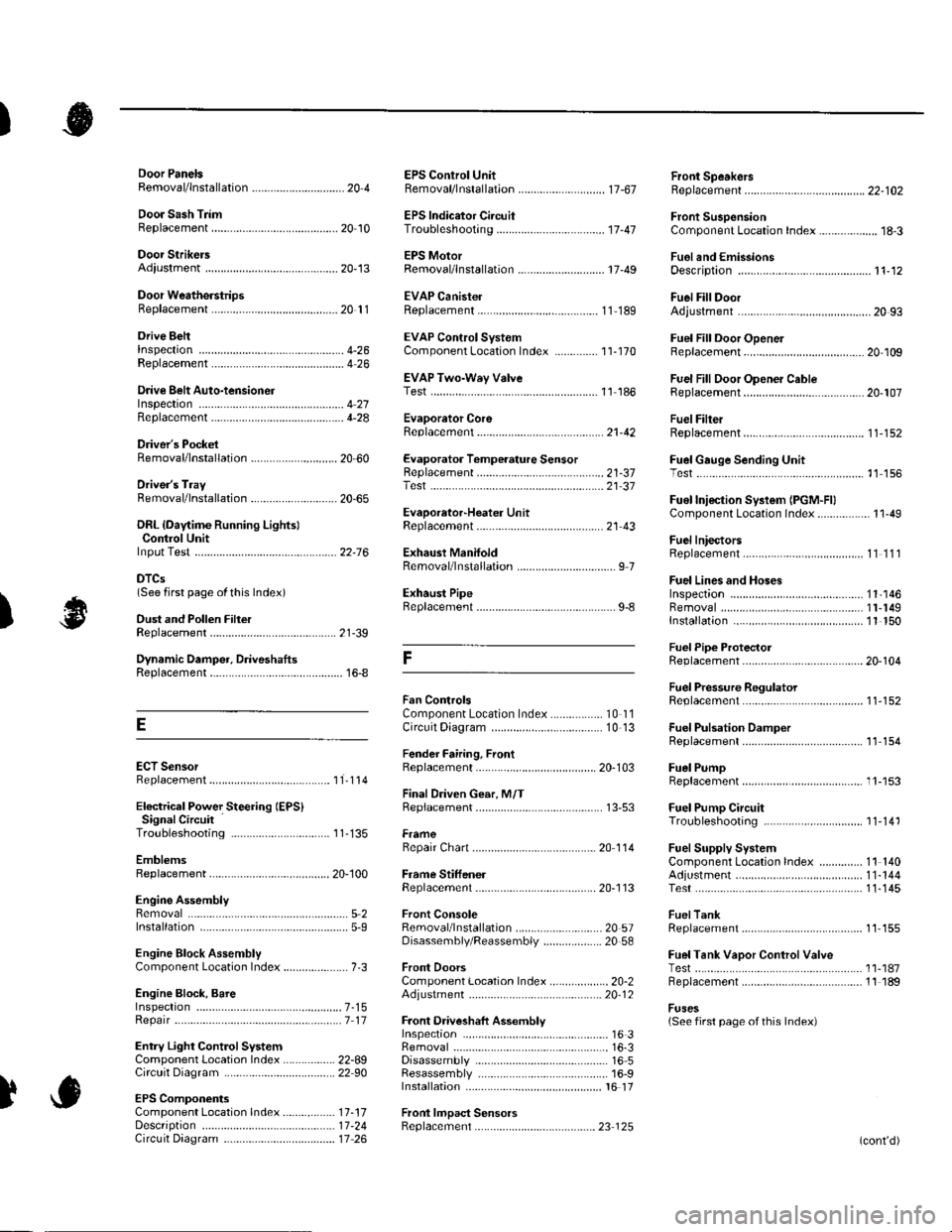
Check for voltage between the No. 6 terminal of
SRS unit connector B (18P) and body ground, and
between the No. 17 terminal and body ground.
There should be 0.5 V or less.
SRS UNIT CONNECTOR B I18P)
WHT/BLK
ls the voltage as specitied?
YES- Faulty SRS uniU replace the SRS unit (see
page 23-1221.a
NO Short to power in the floor wire harness;
replace the floor wire harness.l
't2.
13.
UJ
Page 1135 of 1139

)
Orive BehInspecaron................ 4-26
Door PanelsRemoval/lnstallation -............................. 20-4
Door Sash TrimRep1acement......................................... 20 10
Door StrikersAdiustment ........................................... 20-13
Door Weatherst psBeplacement...........-............................. 20 1 1
EPS Conirol UnitRemoval/1nsta11ation ..................-......... 17-67
EPS Indicator CircuitTroubleshooting ................................... 17 -47
EPS MotorRemoval/lnstallation .-.......................... 17-49
EVAP CanisterRep1acement......................... ......... 11,189
EVAP Control Syst€mComponentLocation Index ..............'11-170
EVAP Two-Wey ValveTest ..........-.............-............................ 11 186
Evaporetor CoreRep1acement........................ . ... 21-42
Evaporator Tomperature SensorReplacement......................................... 21 -37Test..................................... ..........2137
EvaporrtoFHeater UnitReplacement........................................ 21 43
Exhaust ManifoldRemoval/1nsta11ation ................................ I 7
Exhaust Pipe8ep|acement............................................. 9-8
Front SpeakersRep|acement....................................... 22-102
Front SuspensionComponentLocation Index................... 18-3
Fueland EmissionsDescription ........................................... 11-12
Fuel Fill DoorAdjustment ..........-................................ 20 93
Fuel Fill Door OpenetBeplacement........................ . ............ 20.109
Fuel Fill Door Opener CableReplacement....................................... 20- lO7
Fuel FilterReplacement....................................... 1 1-152
Fuel Gauge Sending UnitTest ......................-.-..........-.................. 11'156
Fuel Injection Syslem (PGM"FIlComponent Location 1ndex................. 11-49
Fuel IniectorsRep1acemen1....................................... 1 1 1 1 l
Fuel Lines and HosesInspection .......................................... 1 1'146Removal ....................... . .. . .... 11-149Insta|1ation .......................................... 1 1 150
FuelPipe ProtectolReplacement....................................... 20-104
Fuel Pressure RegulatotReplacement....................................... 1 1-152
Fuel Pulsation DamperReplacemenl................................... 11 154
Fuel PumpReplacement,,,,,.,.,.,,,.,,,,,,,,,,,,.,.,.,,,..,.. 11-153
Fuel Pump CircuitTroubleshooting -.......-....................... 1 1-141
FuelSupply SystemComponent Location lndex .............. 11 140Adjustment................................... 11-144Test........-...-................. ... ............- 11-145
FuelTankBeplacemenl.............. . ..... .. 11 155
Fuel Tank Vapor ControlValveTest ......................-....... ... . . 11-187Replacement,,.,,...,.,,,.,.,,,,... .. .. 11 189
Fuses{See first page ofthis Index)
)
Rep|acement................. ..................... 4 26
Drive Belt Auto-tensionellnspection ............................................... 4 21Rep1acement.................................... ..4-28
Driver's PocketRemoval/lnstallation -........................... 20-60
Driver's TrayRemoval/lnstallation .........................-.- 20-65
DRL {Daytime Running LightslControl Unitlnput Test .................... ........ . . . ......22-16
DTCs(See first page olthis Index)
Dust and Pollen FillerReplacement......................................... 21-39
Dynamic Damper, DriveshaftsReplacement........................................... 16-8
ECT SensorReplacement.,.,,,.,.,,,,,,,,,,,,,,................ 1 1-1 14
El€ctrical Power Steering IEPS)Signal CircuitTroubleshooting ........ ... .. 11-135
EmblemsReplacement......................-................ 20-100
Engine AssemblyRemova1 .................................................... 5 2Installation ............._.................................. 5-9
Engine Block AssemblyComponent Location Inder ..................... 7.3
Engine Block, BareInspect|onRepair
Fan ControlsComponent Location Index................. 10'l 1Circuit Diagram .. ..... . .. . .................. 10 13
Fender Fairing, FrontReplacement...-................................... 20-103
Final Driven Gear. M/TReplacement.... . . ................................ 13-53
FrameRepair Chan............ ... ....................... 20 11 4
Frame StiffenelReplacement......-................................ 20- J'13
Front ConsoleRemoval/lnstallation ............................ 20 5lDisassembJy/Reassemb|y ................... 20 58
Front DoorsComponent Location Index................... 20-2Adiustment ........................................... 20.12
Front Driveshaft AssemblyInspeclion .................... ... ....16 3Remova1...................-...... ... .....16-3Disassembly ............................... .....165Resassemb|y ................................-......... 16-9Insta11arion ........................ ...... ............ l6 17
Front lmpact SensorsRep1acement............................ ...23 125
................7-15................1 11
)
Entry Light Control SystemComponent Location Index ...............-. 22-89Circuit Dia9ram .................................... 22 90
EPS ComponentsComponent Location 1ndex..........-...... 17-!7Description ........................ ...... ..17-24Circuit Diagram11 26(cont'd)
Page 1138 of 1139

Service Manual lndex
(cont'dl
Power Window Switch, Passenger'slnput Test .............-......
Replacement...,-.-.-...,..
Radialor Cap
Rocker Arm AssemblyRemovalD;sassembly/Reassembly
Specifications6-26 (See section 2)22-13022 13222-133..................... 6-27
ComponentLocation Index ..............22 124Circuit Dia9ram .................. ............... 22 125
Ouaner Window Glass8ep1acement ......................................... 20-29
lnstallation6-38
Rocker ArmsTestInspecton6-28
Roof MoldingsReplacement
Seat BeltsComponent Location Index ................... 23-3
Seat 8ehs, FrontReplacementrnspec!on
sRsComponent Location Index ................. 23-13Description ....................................... 23-31Circuit D;agram ... .... ...........2334lnspection/Replacemenl ................... 23 1 126-7
SRS lndicator CircuilTroubleshooting
Startel
Stabilizer BarReplacementFront SuspensionRear Suspension
Stabilizer LinksRemoval/lnstallationFront SuspensionRear Suspension
23 105oSRS UnitReplacement..-.................................... 23-122s
R
1A-1718-30
18 1818-31RadiatorTest......23-9
23-1Replacement ...........
Radiator and Condenser FansCommon CircuitTroubleshooling......... ..... .........21 29
10-310-10Seat Behs, RearReplacement
Seat Cover, FrontReplacement
Seat Cushion Cover, R6ar10-3Replacement
ReplacementTest
Test
20-75
20-84
Overhaul
Starter SolenoidTest..-.-...4-7
Radiator Fan AssemblyTestSeat, Driver'sRemovaf/lnstaf lation ............................ 20 1 1Disassembly/Reassemb1y ................... 20-73
Sedt, Faont Passenger'sDisassembly/Reassemb1y ................... 20-74
Seat, RearRemoval/lnstallation ............................ 20-80
Seat-back Cover, Reer
Starting SystemComponent Location Index...............-..... 4-3CircuitDia9ram ........................................ 4 4
\'{........................ r0-4
Radiator Fan CircuitTroubleshooting
Radiator Fan SwhchReplacementTest
Radiator Fan Switch CircuitTroubleshooting
Rear Air OutletReplacement
Circuil DiagramTest
Rear Window D€rogger WiresRepair
RearWindow GlassReplacement
Troubleshooting10-14
10-1710-17
10 16
17 -3
11-4
17-9
SteeringComponent Location Index................-..Inspectaon ...................
Steering ColumnRemoval/lnstallationReplacementInspection11 11
17-5117 5517 63
20 68
Seat-back Latch, ReaI2Q-104Replacement
Seat-back Striker. RearReplacement
Steering GearboxRemovalOverhaulRear Window DefoggerComponentLocalion Index ..............22 104lnstallation
Steering Hanger BeamReplacement
Steering LinkageInspefiron
Steering LockReplacement
Steering Rack GuideAdiustment
22-10522 106
22-106
SeatsComponent Location Index....-............ 20-70
Shift ForksInspectton13,21
20-25
2l-3621 36
21 25
Disassembly/Reassembly ................... 13-22
Shitt Lever TrimRemoval/lnstallation ............................ 20 61
.....11-12
SecirculationReplacementControl Motor17-13Test.....
Recirculation Control Motor CircuitTroubleshooting
Side Airbag, Drivel'sReplacement
Side lmpact SensorsReplacement
Spark Plugs
23-115
23 123
Side Marker LightRep1acement......................................... 22-A3
17417-6Disassembly/Reassembly ..................... 17 71nsta11ation .............................................. 17-8
SublramesReplacement
Removal
RefrigerantReplacement ..-.-.-...................... 21 53, 54, 55Test ........................................................ 21-56
Retrigerant OilReplacement...............................-........... 21-6. .._..4_19
20 112