2002 HONDA CIVIC tow
[x] Cancel search: towPage 3 of 1139

)
General Information
Ghassis and Paint Codes
-2002 Model ................. 1-2
Chassis and Paint Codes
-2003 Model ................. 1-3
ldentification Number Locations ........ 1-4
Warning/Caution Label Locations ...... 1-5
Under-hood Emission
Control Label ........... .... 1-7
Lift and Support Points .........,....,.......,. 1-8
Towing ...... 1-9
Pafts Marking Locations ...................... 1-10
Page 11 of 1139

Towing
lf the vehicle needs to be towed, call a professional
towing service. Never tow the vehicle behind another
vehicle with just a rope or chain. lt is very dangerous.
Emergency Towing
There are three popular methods of towing a vehicle.
Flat-bed Equipment The operator loads the vehicle
on the back of a truck. This is the best way of
transporting the vehicle.
To accommodate flat-bed equipment. the vehicle is
equipped with towing hooks (A)and tie down hooks {B).
The towing hook can be used with a winch to pull the
vehicle onto the truck, and the tie down hooks slots can
be used to secure the vehicle to truck.
1-9
Wheel Lift Equipment The tow truck uses two
pivoting arms that go under the tires (front or rear) and
lifts them off the ground. The other two wheels remain
on the ground. This is an acceptable way of towing the
vehicle.
Sling-type Equipment The tow truck uses metal
cables with hooks on the ends. These hooks go around
parts of the frame or suspension and the cables lift that
end of the vehicle off the ground. The vehicle's
suspension and body can be seriously damaged if this
method of towing is attemPted.
lf the vehicle cannot be transported by flat-bed, it
should be towed with the front wheels off the ground lf
due to damage, the vehicle must be towed with the
front wheels on the ground, do the following:
. Release the parking brake.. shift the transmission in Neutral.
It is best to tow the vehicle no farther than 50 miles (80
km), and keep the speed below 35 mph (55 km/h).
. lmproper towing preparation will damage the
transmission. Follow the above procedure exactly. lf
you cannot shift the transmission, the vehicle must
be transDorted on a flat-bed.. Trying to lift or tow the vehicle by the bumpers will
cause serious damage, The bumpers are not
designed to support the vehicle's weight.
Page 32 of 1139

Maintenance Schedule
Listed by Distance/Time for Severe Conditions
Service at the indicated distance or time, whichever comes first. Use this schedule if the vehicle is driven MAINLY in Canada or in any of thetollowing conditions; il only OCCASIONALLY driven in these conditions, use the Normal Conditions schedule (see page 3-4).Severe Driving Conditions. Driving less than 5 miles {8 km) per trip or, in freezing temperatures, driving less than 10 miles (16 km) per trip. Driving in extremely hot (over 90"F/32"C) conditions. Extensive idl;ng or long periods of stop and go driving, such as a taxi or a commercial delivery vehicle.. Trailer towing, driving with a car-top carrier, or driving in mountainous conditions.. Driving on muddy, dusty, or de'iced roads
Replace transmission fluid. Use Honda MTF {see page 13 3).
Inspect valve clearance. (cold) (see page 6 32): lntake: 0.21 0.25 mm (0.008 0.010 in.) Exhaust: 0.28 0.32 mm (0.011 0.013 in.)Replace spark plugs.Use IZFR6K 1 1 (N GK) or SKJ20DR'M 1 1 {DENSO)
km/ 6 yearsReplace transmission fluid. Use Honda MTF (see page 13 3).
mil 192,000 km/ 10 years, then every 60,000 mi/ 96,000 km/ 5 yearsReplace coolant (see page 10-6). Capacity: 5.0 015.3 US qt) Use Honda All Season Antifreeze/coo lant Type 2.
3-6
Page 35 of 1139

Listed by Maintenance ltem for Severe Conditions
Use this schedule if the vehicle is driven MAINLY in Canada or in anv of the followina conditions.NOTE: it only OCCASIONALLY driven in theseconditions, use the Normal Conditions schedute.Sovere Driving Conditions. Driving less than 5 miles (8 km) per trip or, in lreezing temperatures, driving less than. Driving in extremely hot over 90 "F 132 'C)conditions.10 miles (16 km) per trip.
. Extensive idling, or long periods ot stop-and-go-driving, such as a taxi or a commercial delivery vehicle.. Trailer towing, driving with a cartop carrier, or driving in mountainous conditions.. Driving on muddy, dusty, or de iced roads.
Service at the indicated distance or time,whichever comes first.miles x 1,000102030405060708090100110120
km x 1,0001648648096112128144160176192
months122436486072
Replace engine oilReplace every 5,000 miies 18,000 km)or 6 months
Rotate tires{Checktire intlation and condition at leastonce per monthiaoaaoaaoaaao
Replace engine oil fiher
Inspect front and rear brakes
Lubricate all locks, hinges, and latches
Visually inspect the following items:. Tie rod ends, steering gearbox and boots. Suspension components' Driveshaft boots
Checl parking brale adjuslmentaaOaoa
Visually inspect the following items:. Brake hoses and lines {including ABSi. Allfluid levels and condition oflluids. Exhaust system*. Fuel lines and connections*. Lights and controls, vehicle underbody
Inspect and adjust drive behoaoa
Replace dust and pollen filter"o't'
Replace transmission lluidaa
Service the following items atthe recommended interuals
Replace air cleaner elementEvery 15,000 miies (24,000 km) in dusty conditions, otheMise use normal schedule.
Replace spark plugsEvery 110,000 miles (176,000 km)
Inspect valve clearanceInspect every 110,000 miles (176,000 km), otheMise adiust only if noisy.
Inspect idle speed'Every 160,000 miles (256,000 km)or8 vears
Replace engine coolantAt 120,000 miles (192,000 km) of 10 years,lhen every 60,000 miles (96,000 km)or 5
Replace brake fluidEvery 3 years
* : According to state and federal regulations, failure to do the maintenance items marked with asterisk 1*)will not void customer's emissionswarranties. However, Honda recommends that all maintenance service be done at the recommended interval to ensure long{erm reliabilitv.
NOTE 1: Replace the dust and pollen filter at 15,000 miles/24,000 km if the vehicle is driven mostly in urban areas that have high concentrationsof soot in the air from industrv and diesel-Dowered vehicles.
t,
3-9
Page 52 of 1139

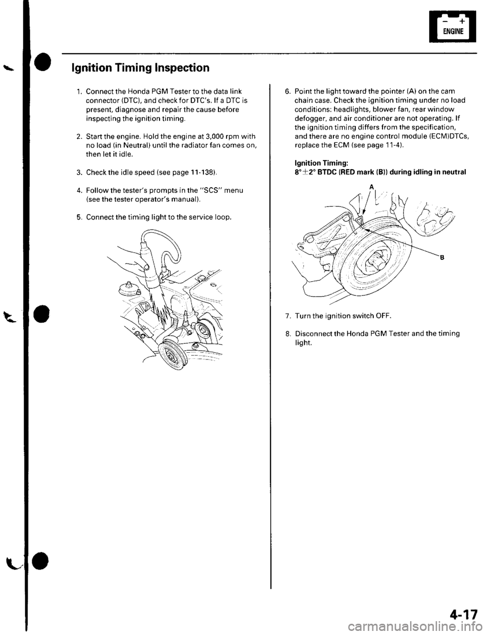
lgnition Timing Inspection
1.
4.
5.
Connect the Honda PGM Tester to the data link
connector (DTC), and check for DTC'S. lf a DTC is
present, diagnose and repair the cause before
inspecting the ignition timing.
Startthe engine. Hold the engine at 3,000 rpm with
no load (in Neutral) until the radiator fan comes on,
then let it idle.
Check the idle speed (see page 11-138).
Follow the tester's prompts in the "SCS" menu
{see the tester operator's manual),
Connect the timing light to the service loop.
o
6. Point the light toward the pointer (A) on the cam
chain case. Check the ignition timing under no load
conditions: headlights, blower fan. rear window
defogger, and air conditioner are not operaling. lf
the ignition timing differs from the specification,
and there are no engine control module {ECM)DTcs,
replace the ECM (see page 11-4)
lgnition Timing:
8"+2" BTDC {RED mark {B)) during idling in neutral
A
7. Turn the ignition switch OFF.
Disconnectthe Honda PGM Tester and thetiming
light.
4-17
Page 128 of 1139

Valve Guide Replacement
Special Tools Required. Valve guide driver, 5.5 mm 07742-0010100. Valve guide reamer, 5.5 mm 07HAH-PJ7o108
1.Inspect valve stem-to-guide clearance (see page 6-
32t.
As illustrated below, use a commercially available
air-impact valve guide driver (A) modified to fit the
diameter of the valve guides. In most cases, the
same procedure can be done using the special tool
and a conventional hammer.
10.8 mm{0.,|2 in.)
3. Select the proper replacement guides, and chill
lhem in the freezer section of a refriqerator for
about an hour.
4. Use a hot plate or oven to evenly heat the cylinder
head to 300'F (150"C). Monitor the temperature
with a cooking thermometer. Do not getthe head
hotterthan 300'F (150"C); excessive heat may
loosen the valve seats.
-_|Jfillr-.-4fi'11., -
tT
7.
Working from the camshaft side. use the driver and
an aar hammerto drive the guide about 2 mm (0.1
in.)towards the combustion chamber. This will
knock off some of the carbon and make removal
easier. Hold the air hammer directly in line with the
valve guide to prevent damaging the driver.
Turn lhe head over, and drive the guide out toward
the camshaft side of the head.
lf a valve guide won't move, drill it out with a I mm
(5/16 inch) bit. then try again. Drill guides only in
extreme cases;you could damage the cylinder
head if the guide breaks.
Remove the new guide(s) from the freezer, one at a
time, as vou need them.
(cont'd)
6-33
Page 132 of 1139

Valves, Springs, and Valve Seals Installation
Special Tools Required
Valve spring compressor attachment 07VAE-00101 0A
1. Coat the valve stems with engine oil. lnstall the
valves in the valve guides.
2. Check that the valves move up and down smoothly.
Installthe spring seats on the cylinder head.
Install the new valve seals (A) using the valve guide
seal installer (B).
NOTE: The exhaust valve seal (C) has a black spring(D), and the intake valve seal (E) has a white spring(F). They are not interchangeable.
6.
lnstallthe valve spring. Place the end ofthe valve
spring with closely wound coils toward the cylinder
n eao.
Install the valve retainer.
Installthe valve spring compressor, Compress the
spring, and install the valve keepers. Remove the
valve spring compressor.
Lightly tap the end of each valve stem two or three
times with a plastic mallet (A) to ensure proper
seating of the valve and valve keepers. Tap the
valve stem only along its axis so you do not bend
the stem.
7.
6-37
Page 143 of 1139

Connecting Rod and Crankshaft End Play Inspection
1.Remove the oil pump (see page 8-9).
Remove the baffle plates (see step 6 on page 1 -12).
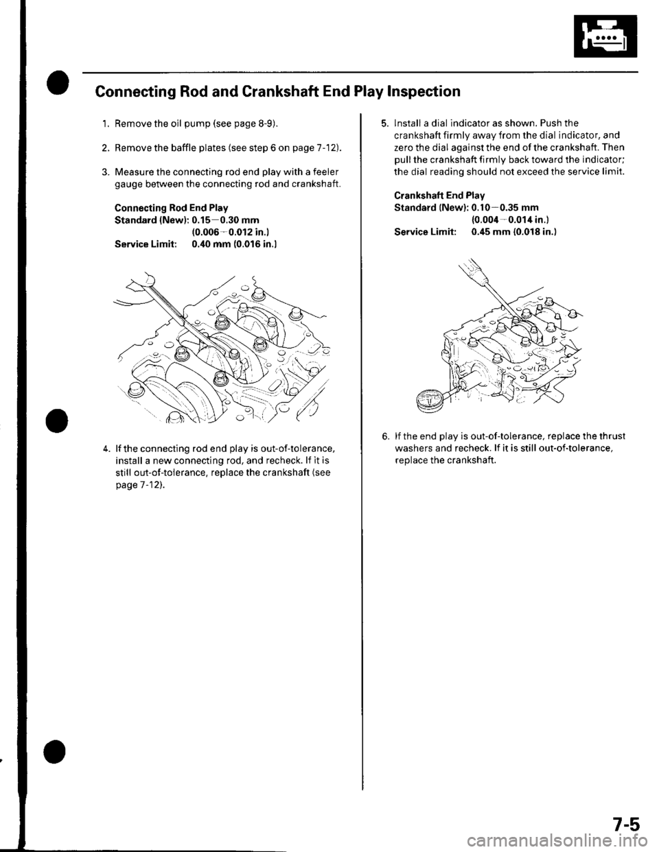
3. Measure the connecting rod end play with a feeler
gauge between the connecting rod and crankshaft.
Connecting Rod End Play
Standard {New): 0.15 0.30 mm(0.006-0.012 in.l
Service Limit 0.40 mm (0.016 in.l
4.lf the connecting rod end play is out-of-tolerance,
install a new connecting rod, and recheck. lf it is
still out-of-tolerance, replace the crankshaft (see
page 7 -12],.
5. lnstall a dial indicator as shown. Push the
crankshaft firmly away from the dial indicator, and
zero the dial against the end of the crankshaft. Then
pull the crankshaft firmly back toward the indicator;
the dial reading should not exceed the service limit.
Crankshaft End Plav
Standard lNew): 0.10-0.35 mm
{0.004-0.014 in.l
Service Limit: 0.45 mm {0.018 in.)
lf the end play is out-of-tolerance, replace the thrust
washers and recheck. lf it is still out-of-tolerance,
replace the crankshaft.
7-5