2002 HONDA CIVIC wheel
[x] Cancel search: wheelPage 7 of 1139

!
..r'
, I O warning/cautionLabelLocations
NOTE: FRONT PASSENGER AIRBAG WARNING TAG(CHILD SEAT) is installed on the glove box on the U.S.
mooet.
Passenger's Compartment:
SRS INFORMATIONU.S. model
SRS WARNINGINFORMATION
FRONT PASSENGERMODULE DANGER
MONITORNOTICE
SIDE AIRBAG CAUTIONLocated on driver'sano passen9er sdoorjamb (not shown)
SIDE MODULEDANGER
,/
FRONTSEATBELTTENSIONERCAUTION
Steering Wheel:
DRIVER MODULEDANGER
CABLE REELCAUTION
(cont'd)
1-5
Page 10 of 1139

General Information
Lift and Support Points
NOTE: If you are going to remove heavy componentssuch as suspension or the fuel tank from the rear of thevehicle, first supportthe front ofthe vehicle with tallsafety stands. When substantialweight is removed
from the rear of the vehicle, the center of gravity canchange and cause the vehicle to tip forward on the hoist.
Frame Hoist
1. Position the hoist lift blocks (A), or safety stands,under the vehicle's front support points (B) and rearsupport points (C).
2. Raise the hoist a few inches, and rock the vehiclegently to be sure it is firmly supported.
3. Raise the hoistto full height, and inspectthe liftpoints for solid contact with the lift blocks.
Safety Stands
To support the vehicle on safety stands. use the samesuppon points (B and C) as for a frame hoist, Alwaysuse satety stands when working on or under anyvehicle that is supported only by a jack.
1-8
Floor Jack
1. Set the parking brake.
2. Block the wheels that are not being lifted.
3. When lifting the rear of the vehicle. put thegearshift Iever in reverse.
4. Position the floor jack under the front jacking
bracket (A) or rear jacking bracket (B), center thejacking bracket in the jack lift ptatform (C), and jack
up the vehicle high enough to fit the safety standsunder it.
c
Position the safety stands underthe support points
and adjust them so the vehicle will tevet.
Lower the vehicle onto the stands.
0
Jt
Page 11 of 1139

Towing
lf the vehicle needs to be towed, call a professional
towing service. Never tow the vehicle behind another
vehicle with just a rope or chain. lt is very dangerous.
Emergency Towing
There are three popular methods of towing a vehicle.
Flat-bed Equipment The operator loads the vehicle
on the back of a truck. This is the best way of
transporting the vehicle.
To accommodate flat-bed equipment. the vehicle is
equipped with towing hooks (A)and tie down hooks {B).
The towing hook can be used with a winch to pull the
vehicle onto the truck, and the tie down hooks slots can
be used to secure the vehicle to truck.
1-9
Wheel Lift Equipment The tow truck uses two
pivoting arms that go under the tires (front or rear) and
lifts them off the ground. The other two wheels remain
on the ground. This is an acceptable way of towing the
vehicle.
Sling-type Equipment The tow truck uses metal
cables with hooks on the ends. These hooks go around
parts of the frame or suspension and the cables lift that
end of the vehicle off the ground. The vehicle's
suspension and body can be seriously damaged if this
method of towing is attemPted.
lf the vehicle cannot be transported by flat-bed, it
should be towed with the front wheels off the ground lf
due to damage, the vehicle must be towed with the
front wheels on the ground, do the following:
. Release the parking brake.. shift the transmission in Neutral.
It is best to tow the vehicle no farther than 50 miles (80
km), and keep the speed below 35 mph (55 km/h).
. lmproper towing preparation will damage the
transmission. Follow the above procedure exactly. lf
you cannot shift the transmission, the vehicle must
be transDorted on a flat-bed.. Trying to lift or tow the vehicle by the bumpers will
cause serious damage, The bumpers are not
designed to support the vehicle's weight.
Page 21 of 1139

Y
2-9
o
o
a
0 10 mm (0 0.39 in.)Rotational olav measured at outside
29 N (3.0 kgf.6.6lbs)Starting load measured at outside
Angle of rack guide screw loosened
n
ItemMeasurementOualiticationStandard or New Service Limit
WheelalignmentCamberFront0'00' 45'
Rear0'45'- 45
CasterFront1"33'�11"
TotalToelryttRear
0-3 mm (0::0.12 in.)
lN 2 ' , mm (0.08 "' ,, in.)
Frontwheel turning anglelnside wheel37'40'-2'
Outside wheel29'50'(Reference)
Aluminum wheel runoutAxial0 0.7 mm (0 0.03 in.) 2.0 mm (0.08 in.)
Radial0 - 0.7 mm (0 0.03in.) l.5mm{0.06in.)
WheelbearingEnd playFront0 0.05 mm (0 0.002 in.)
Rear0 0.05 mm (0 0.002 in.)
Page 24 of 1139

cont'
ItemMeasuremeniOualificationSpecilicationSTEERINGTypeElectric, Power assisted rack and pinion
Overall ratio15.1Turns,lock to-lock
Steering wheel diameter360 mm (14.2 in)SUSPENSIONTypeIndependent srrul with stabiliTer. coil springRearDouble wishboneShock absorberFrontTelescopic, hydraulic. nitrogen gas-frlled
RearTelescopic, hydraulic, nitrogen gas,filledWHEEL
ALIGNMENT
CamberFront0"00'
Bear0.45'�
CasterFront1'33'�TotaltoeFront0 mm (0 in.)
RearIn 2 mm (1/16 in.)BRAKESType of service brakeFrontPowerassisted self-adjusling ventilated disc
BearPower-assisted self-adjusting solid discType of parking brakeMechanical actuating, rear wheelsPad friction surface areaFront45 cm'(7.0 sq in.)x2
Rear28 cm'(4.3 sq in.) x 2TIRESSize offront and reartiresPl95/60 815 88VSize o{ spare tireT125r0 D15 95MAIR
CONDITIONING
CompressorTypeScroll
Number of
cylinders
Capacity85.7 m015.23 cu in.)/rev.
Maximum speed12,000 rpm
Lubricant capacity130 m0 {4 1/3 floz)
LubricanttypeSP-10 (P/N 38897'P13-A01AH or38899-P13 A01)CondenserTypeCorrugated finEvaporatorTvpeCorrugated fin
BlowerTypeSirocco fan
Motor type220 Wl12 V
Speed control4 Speeo
Maximum capacity480 m" 116.900 cu ft)/hTemperature controlAirmixtype
Compressor clutchTvpeDry, single plate, poly-V belt drive
Electricalpower
cons!mptron at
68"F (20.C)
42 W maximum at 12 V
RefrigerantTypeHFC 134a (R-134a)
Capacity500 550 g (17.6 19.4 oz)
Design Specifications
C
aL
2-12
../ a
Page 40 of 1139

Starter Circuit Troubleshooting
NOTE:. Airtemperature must be between 59'and 100'F (15'
and 38'C) during this procedure.
. After this test, or any subsequent repair, reset the
engine controle module (ECM) to clear any diagnostlc
trouble codes (DTCS) {see page 11-4).. The battery must be in good condition and fully
charged.. lf you disconnect the baftery, do the ECM idle learn
procedure (see page 11-139).
Recommended Procedure:. Use a starter system tester.. Connect and operate the equipment in accordance
with the manuf acturer's instructions.
Alternate Procedure
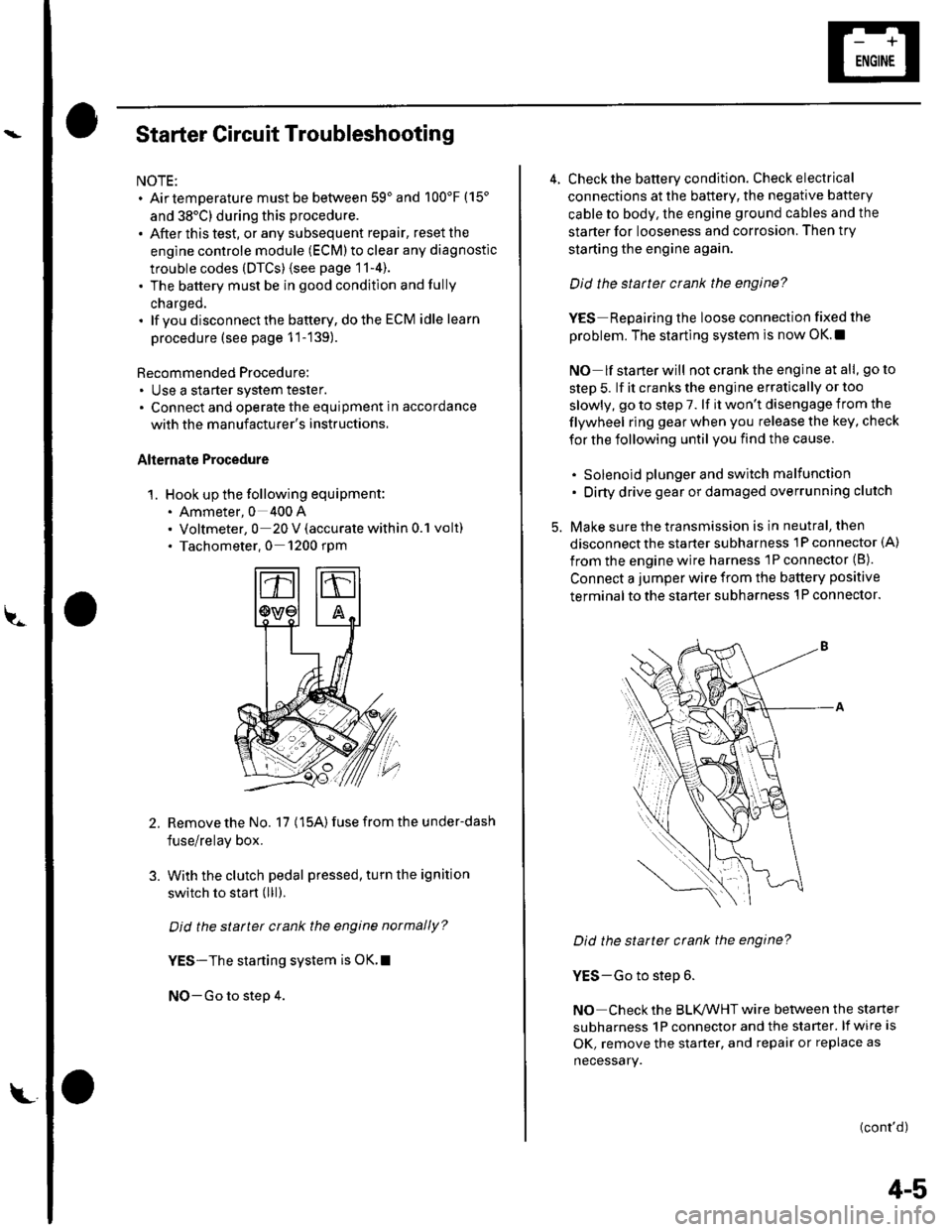
1. Hook up the following equipment:. Ammeter, 0 400 A. Voltmeter, 0 20 V (accurate within 0.1 volt). Tachometer,0 1200 rpm
2.Remove the No. 17 (15A) fuse from the under-dash
fuse/relay box.
With the clutch pedal pressed, turn the ignition
switch to start (lll).
Did the starter crank the engine normally?
YES-The starting system is OK.I
NO-Go to step 4.
3.
L
4-5
4. Check the battery condition. Check electrical
connections at the battery, the negative baftery
cable to body, the engine ground cables and the
starter for looseness and corrosion. Then try
starting the engine again.
Did the statter crank the engine?
YES Repairing the loose connection fixed the
problem. The starting system is now OK.!
NO lf starterwill notcranktheengine atall, goto
step 5. lf it cranks the engine erratically or too
slowly, go to step 7. lf it won't disengage from the
flywheel ring gear when you release the key, check
for the following until you find the cause.
. Solenoid plunger and switch malfunction. Dirty drive gear or damaged overrunning clutch
5. Make sure the transmission is in neutral, then
disconnect the starter subharness 1P connector (A)
from the engine wire harness 'lP connector (B).
Connect a jumper wire from the battery positive
terminal to the starter subharness 'l P connector.
Did the starter crank the engine?
YES-Go to step 6.
NO Check the BLK,ANHT wire between the starter
subharness 1P connector and the starter. lf wire is
OK, remove the starter, and repair or replace as
necessary.
(cont'd)
Page 41 of 1139

Starting System
Starter Circuit Troubleshooting
(cont'dl
6. Check the following items in the order listed untilyou find the open circuit.
. Check the BLIVWHT wire and connectors
between the under-dash fuse/relay box and theignition switch, and between the under-dash
fuse/relay box and the starter.. Check the ignition switch {see page 22-53).. Check the clutch interlock switch and connector.. Check the starter cut relay (see page 22-51).. Check LT GRN wire between the starter cut relayl
under-dash fuse/relay box and the clutch
interlock switch.. Check the BLK wire between the clutch interlock
switch and G501.
7, Check the cranking voltage and current draw.
ls ctanking voltage greatet than or equal to 8.7 V
and current draw less than or equal to 230 A?
YES-Go to step 8.
NO Replace the starter. or remove and
disassemble it, and check these items until you find
the cause.
. Starter armature dragging. Shorted armatu re winding. Excessive drag in engine
8. Check the engine speed while cranking the engine.
ls the engine speed above 100 tpm?
YES Go to step 9.
NO-Replace the starter, or remove and
disassemble it, and check for the following untilyou find the cause.
. Excessively worn starter brushes. Open circuit in commutator brushes. Open circuit in starter armature commutator
segments. Dirty or damaged helical splines or drive gear. Faulty drive gear clutch
9. Remove the starter, and inspect its drive gear andthe flywheel ring gear for damage. Replace anydamaged pans.I
4-6
Clutch Interlock Switch Test
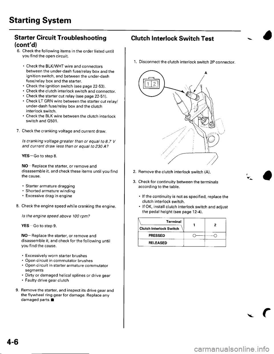
1. Disconnect the clutch interlock switch 2P connector.
2. Remove the clutch interlock switch (A).
Check for continuity between the terminals
according to the table.
. lf the continuity is not as specified, replace the
clutch interlock switch.. lf OK, install clutch interlock switch and adjust
the pedal height (see page 12-4l..
Terminal
Cl","f ri"t.tf ."tS""*Jrl2
PRESSEDo--- --o
RELEASED
Page 49 of 1139

Starting System
Starter Overhaul (cont'dl
Planetary Gear Inspection
16. Check the planetary gears (A) and ring gear {B).Replace them if they are worn or damaged.
Overrunning Cluich Inspection
17. Slide the overrunning clutch along the shaft.
Replace it if it does not slide smoothly.
18. Rotate the overrunning clutch (A) both ways.
Does it lock in one direction and rotate smoothly inreverse? lf it does not lock in either direction or it
locks in both directions, replace it.
lf the starter drive gear (B) is worn or damaged,
replace the overrunning clutch assembly; the gear
is not available separately.
Check the condition of the flywheel ring gear.
Replace it if the starter drive gear teeth are
oamageo.
19.
4-14
i.-
Starter Reassembly
20, Pry back each brush spring with a screwdriver, thenposition the brush about halfway out of its holder,
and release the spring to hold it there.
NOTE: To seatthe new brushes. slip a strip of #5OO
or # 600 sandpaper. with the grit side out, be&veen
the commutator and each brush, and smoothly
rotate the armature. The contact surface of the
brushes will be sanded to the same contour as the
commutator.
21lnstallthe armature in the housing, and installthe
brush holder. Next, pry back each brush spring
again, and push the brush down until it seats
against the commutator, then release the spring
against the end of the brush.
s
Install the starter end cover to retain the brush
holder.