2002 HONDA CIVIC ECU
[x] Cancel search: ECUPage 1024 of 1139
I
J
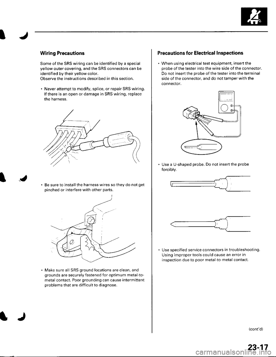
Wiring Precautions
Some of the SRS wiring can be identified by a special
yellow outer covering, and the SRS connectors can be
identified by their yellow color.
Observe the instructions described in this section.
. Never attempt to modify. splice, or repair SRS wiring.
lf there is an open or damage in SRS wiring, replace
the harness.
Be sure to install the harness wires so they do not get
Dinched or interfere with other Darts.
Make sure all SRS ground locations are clean, and
grounds are securely fastened for optimum metal-to-
metal contact. Poor grounding can cause intermittent
problems that are difficult to diagnose.
Precautions for Electrical Inspections
. When using electricaltest equipment, insertthe
probe of the tester into the wire side of the connector.
Do not insert the probe of the tester into the terminal
side of the connector, and do not tamper with the
connector.
Use a U-shaped probe. Do not insert the probe
forcibly.
Use specified service connectors in tro u bleshooting.
Using improper tools cou ld cause an error in
inspection due to poor metal-to-metal contact.
(cont'd)
23-17
Page 1033 of 1139
sRs
General Troubleshooting Information (cont'dl
Erasing the DTG Memory
Specisl Tool Required
SCS service connector 07PAz-0010100
To erase the DTC(S)from the SRS unit, use a Honda
PGM Tester {see lhe Honda PGfM Tester SRS Vehicle
System Supplement) or the following procedure.
1. Make sure the ignition switch is OFF.
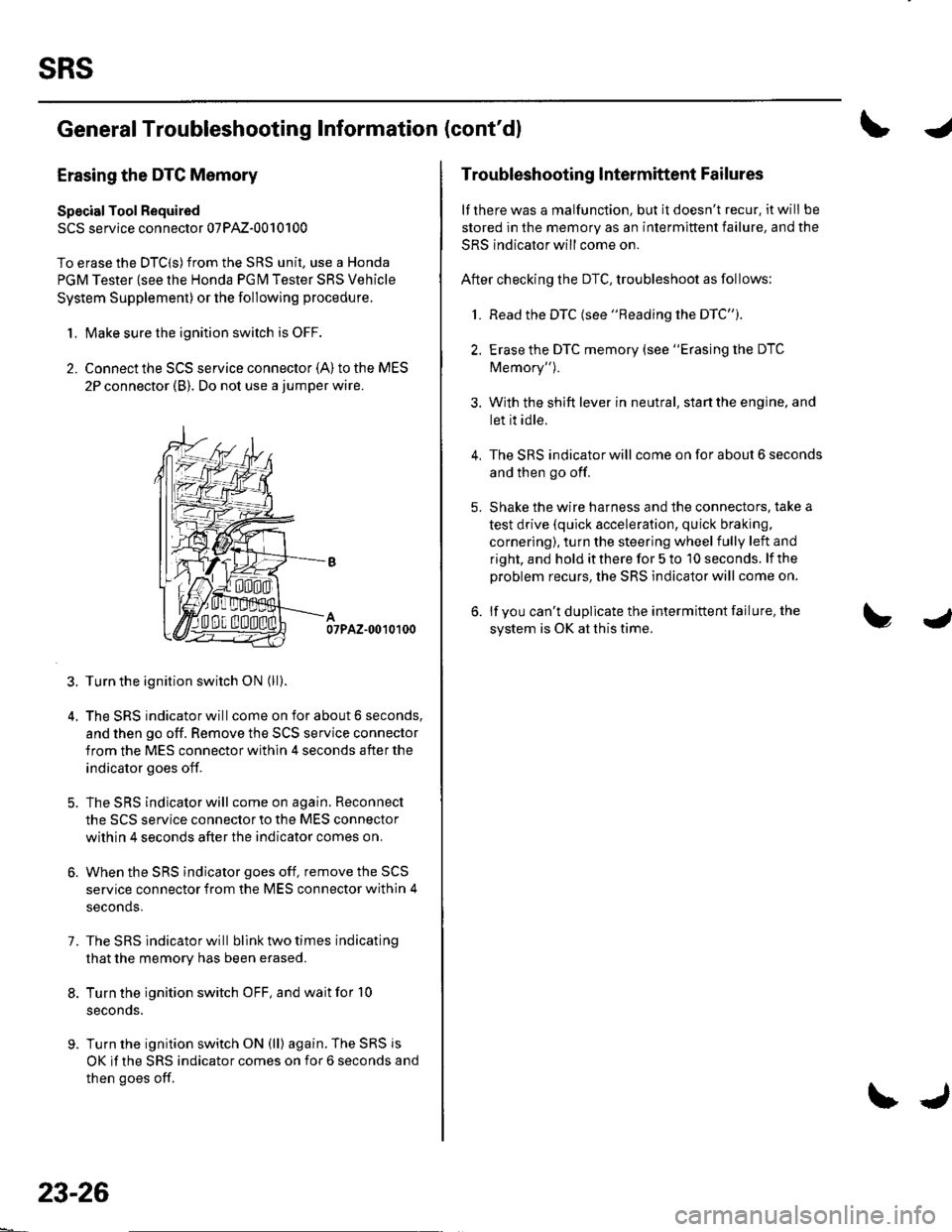
2. Connect the SCS service connector {A) to the MES
2P connector (B). Do not use a jumper wire.
07PAZ-0010100
3. Turn the ignition switch ON (ll).
4. The SRS indicator will come on for about 6 seconds,
and then go off. Remove the SCS service connector
from the MES connector within 4 seconds after the
indicator goes off.
5. The SRS indicator will come on again. Reconnect
the SCS service connector to the MES connector
within 4 seconds after the indicator comes on.
6. When the SRS indicator goes off, remove the SCS
service connector from the MES connector within 4
seconds.
7. The SRS indicator will bllnk two times indicating
that the memory has been erased.
8. Turn the ignition switch OFF, and wait for '10
seconds.
9. Turn the ignition switch ON (ll) again. The SRS js
OK if the SRS indicator comes on for 6 seconds and
then goes off.
23-26
\J
Troubleshooting lntermittent Failures
lf there was a malfunction, but it doesn't recur. it will be
stored in the memory as an intermittent failure, and the
SRS indicator will come on.
After checking the DTC, troubleshoot as follows:
1. Read the DTC (see "Reading the DTC").
2. Erase the DTC memory (see "Erasing the DTC
Memory").
3. With the shift lever in neutral, start the engine, and
let it idle.
The SRS indicator will come on for about 6 seconds
and then go off.
Shake the wire harness and the connectors. take a
test drive (quick acceleration, quick braking,
cornering), turn the steering wheel fully left and
right, and hold it there for 5 to '10 seconds. lf the
problem recurs, the SRS indicator will come on.
lf you can't duplicate the intermittent failure, the
system is OK at this time.
4.
Page 1038 of 1139
ISystem Description
SRS Components
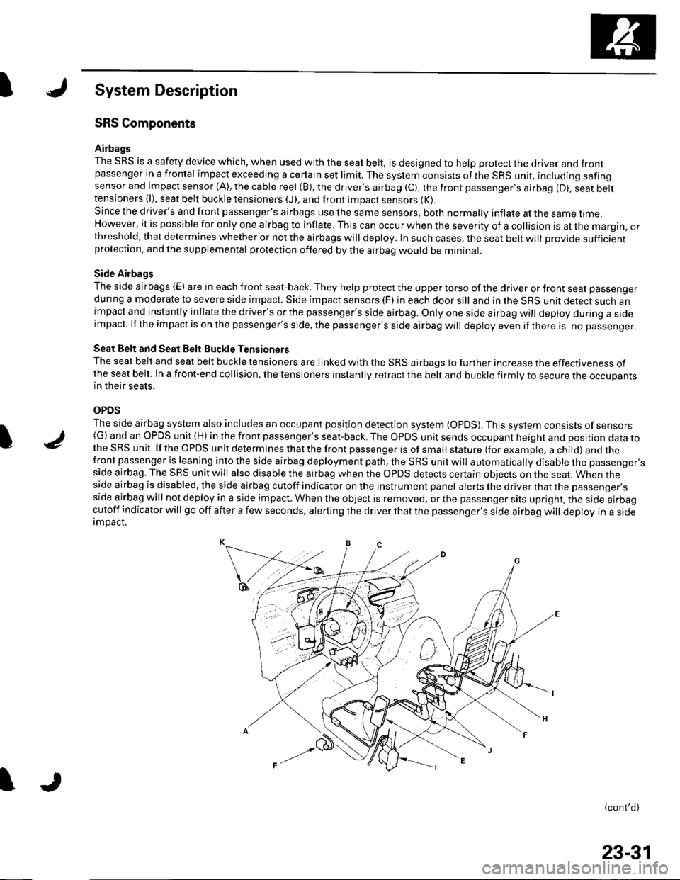
Airbags
The SRS is a safety device which, when used with the seat belt, is designed to help protect the driver and frontpassenger in a frontal impact exceeding a certain set limit. The system consists ofthe SRS unit, including safingsensor and impact sensor (A), the cable reel (B), the driver's airbag (C), the front passenger,s airbag (D). seat belttensioners (l), seat belt buckle tensioners (J), and front impact sensors (K).
Since the driver's and front passenger's airbags use the same sensors, both normally inflate at the same ttme.However, it is possible for only one airbag to inflate. This can occur when the severity of a collision is at the margin, orthreshold, that determines whether or not the airbags will deploy. In such cases, the seat belt will provide sufficientprotection, and the supplemental protection offered by the airbag would be mininal.
Side Airbags
The side airbags (E) are in each front seat-back. They help protect the upper torso of the driver or front seat passenger
during a moderate to severe side impact. Side impact sensors (F) in each door sill and in the SRS unit detect such animpact and instantly inflate the driver's or the passenger's side airbag. Only one side airbag will deploy during a sideimpacl. lf the impact is on the passenger's side, the passenger's side airbag will deploy even if there is no passenger.
Seat Belt and Seat Belt Buckle Tensioners
The seat belt and seat belt buckle tensioners are linked with the SRS airbags to further increase the effectiveness ofthe seat belt. ln a front-end collision, the tensioners instantly retract the belt and buckle firmly to secure the occupantsin their seats.
OPDS
The side airbag system also includes an occupant position detection system (OpDS). This system consists of sensors(G)and an OPDS unit (H) in the front passenger's seat-back. The OPDS unit sends occupant heighl and position data tothe SRS unit. lf the OPDS unit determines that the front passenger is of small stature (for example, a child) and thefront passenger is leaning into the side airbag deployment path, the SRS unit will automatically disable the passenger'sside airbag. The SRS unit will also disable the airbag when the OPDS detects certain obiects on the seat. When theside airbag is disabled, the side airbag cutoff indicator on the instrument panel alerts the driver that the passenger'sside airbag will not deploy in a side impact. When the object is removed, or the passenger sits upright, the side airbagcutoff indicator will go off after a few seconds, alerting the driver that the passenger's side airbag will deploy in a sideimDact.
(cont'd)
I
23-31
Page 1120 of 1139
A
\'l9
Driver's Airbag Replacement
Removal
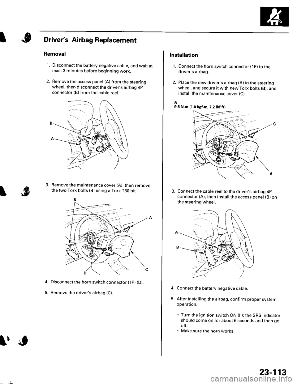
1. Disconnectthe battery negative cable, and wait atleast 3 minutes before beginning work.
2. Remove the access panel (A) from the steering
wheel, then disconnect the driver's airbag 4p
connector (B)from the cable reel.
Remove the maintenance cover (A), then remove
the two Torx bolts (B) using a Torx T3O bit.
Disconnect the horn switch connector (1P) (D).
Remove the driver's airbag (C).5.
lfc
23-113
Installation
1. Connect lhe horn switch connector (1P) to thedriver's airbag.
2. Place the new driver's airbag (A) inthesteering
wheel, and secure it with new Torx bohs (B), and
installthe maintenance cover (C).
a9.8 N.m {1.0 kgf.m, 7.2 lbt.ft)
Connect the cable reel to the driver's airbag 4P
connector (A), then installthe access panel (B) on
the steering wheel.
Connect the battery negative cable.
After installing the airbag, confirm proper system
operation:
. Turn the ignition switch ON (ll); the SRS indicator
should come on for about 6 seconds and then go
off.. Make sure the horn works.
4.
5.
Page 1122 of 1139
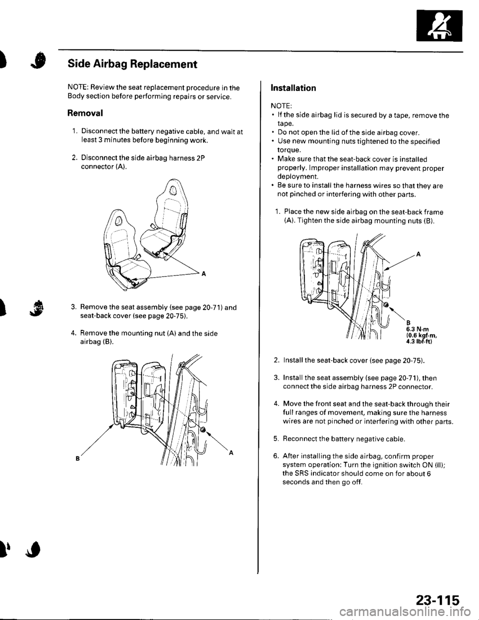
)Side Airbag Replacement
)
NOTE: Review the seat replacement pro6edure in the
Body section before pertorming repairs or service.
Removal
1. Disconnectthe battery negative cable, and wait atleast 3 minutes before beginning work.
2. Disconnect the side airbag harness 2P
connector {A).
Remove the seat assembly (see page 20-71) and
seat-back cover (see page 20-75).
Remove the mounting nut (A) and the side
airbag (B).
3.
l,o
23-115
Installation
NOTE:. lf the side airbag lid issecured byatape, removelhe
rape.. Do not open the lid of the side airbag cover.. Use new mounting nuts tightened to the specified
torque.. Make sure that the seat-back cover is installedproperly, lmproper installation may prevent proper
deployment.. Be sure to install the harness wires so that they arenot pinched or interfering with other parts.
1. Place the new side airbag on the seat-back frame(A). Tighten the side airbag mounting nuts (B).
2. Installthe seat-back cover {see page 20-75).
3. Installthe seat assembly (see page 20-71), then
connect the side airbag harness 2P connector.
4. Move the front seat and the seat-back through their
full ranges of movement, making sure the harness
wires are not pinched or interfering with other parts.
5. Reconnect the battery negative cable.
6. After installing the side airbag, confirm proper
system operation;Turn the ignition switch ON (ll);
the SRS indicator should come on for about 6
seconds and then go off.
Page 1123 of 1139
sRs
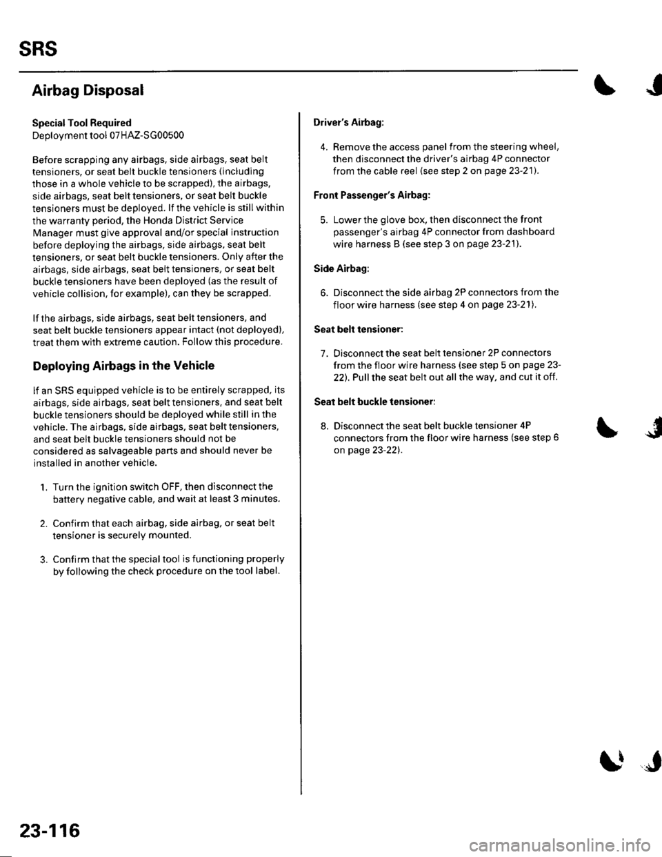
Airbag Disposal
Special Tool Required
Deployment tool 07HAz-SG00500
Before scrapping any airbags, side airbags, seat belt
tensioners, or seat belt buckle tensioners (including
those in a whole vehicle to be scrapped), the airbags,
side airbags, seat belt tensioners, or seat belt buckle
tensioners must be deployed. lf the vehicle is still within
the warranty period, the Honda District Service
Manager must give approval and/or special instruction
before deploying the airbags, side airbags, seat belt
tensioners, or seat belt buckle tensioners. Only after the
airbags, side airbags, seat belt tensioners, or seat belt
buckle tensioners have been deployed (as the result of
vehicle collision, for example), can they be scrapped.
lf the airbags, side airbags, seat belt tensioners, and
seat belt buckle tensioners appear intact (not deployed),
treat them with extreme caution. Follow this Drocedure.
Deploying Airbags in the Vehicle
lf an SRS equipped vehicle is to be entirely scrapped, its
airbags, side airbags. seat belt tensioners. and seat belt
buckle tensioners should be deoloved while still in the
vehicle. The airbags, side airbags, seat belttensioners,
and seat belt buckle tensioners should not be
considered as salvageable parts and should never be
installed in another vehicle.
1. Turn the ignition switch OFF, then disconnect the
battery negative cable, and wait at least 3 minutes.
2. Confirm that each airbag, side airbag, or seat belt
tensioner is securely mounted.
3. Conf irm that the specia I tool isfunctioning properly
by following the check procedure on the tool label.
23-116
$J
Driver's Airbag:
4. Remove the access panel f rom the steering wheel,
then disconnect the driver's airbag 4P connector
from the cable reel (see step 2 on page 23-21).
Front Passenger's Airbag:
5. Lowerthe glove box, then disconnectthe front
passenger's airbag 4P connector from dashboard
wire harness B (see step 3 on page 23-211.
Side Airbag:
6. Disconnect the side airbag 2P connectors from the
floor wire harness (see step 4 on page 23-211.
Seat belt tensioner:
7. Disconnect the seat belt tensioner 2P connectors
from the floor wire harness {see step 5 on page 23-
22). Pull the seat belt out all the way, and cut it off.
Seat belt buckle tensioner:
8, Disconnect the seat belt buckle tensioner 4P
connectors from the floor wire harness (see step 6
on page 23-221.
Page 1124 of 1139
)
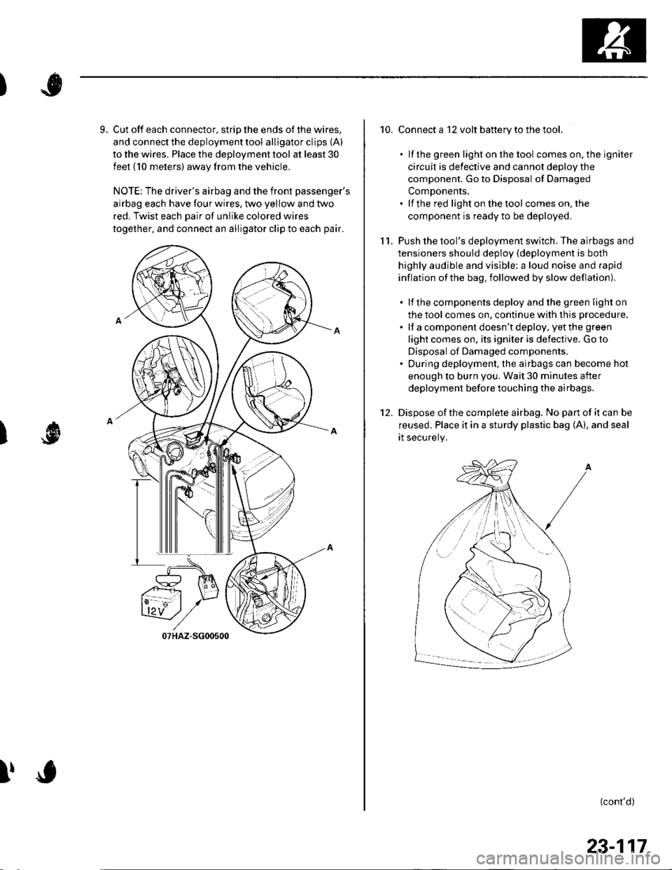
9. Cut off each connector, strip the ends of the wires,
and connect the deployment tool alligator clips (A)
to the wires. Place the deployment tool at least 30
feet (10 meters) away from the vehicle.
NOTE: The driver's airbag and the front passenger's
airbag each have four wires, two yellow and two
red. Twist each Dair of unlike colored wires
together, and connect an alligator clip to each pair.
I
!
10. Connect a 12 volt battery to the tool.
. lf the green light on the tool comes on, the igniter
circuit is defective and cannot deDlov the
component. Go to Disposal of Damaged
ComDonents.. lf the red light on the tool comes on, the
component is ready to be deployed.
11. Push the tool's deployment switch. The airbags and
tensioners should deploy (deployment is both
highly audible and visible: a loud noise and rapid
inflation of the bag, followed by slow deflation).
. lf the components deploy and the green light on
the tool comes on, continue with this procedure.
. lf a component doesn't deploy, yet the green
light comes on, its igniter is defective. Go to
Disposal of Damaged components.. During deployment, the airbags can become hot
enough to burn you. Wait 30 minutes after
deployment before touching the airbags.
12. Dispose ofthe complete airbag. No pan of it can be
reused. Place it in a sturdy plastic bag (A), and seal
rt securery.
(cont'd)
/:
i'..-':
23-117
Page 1136 of 1139
Service Manual Index
(cont'dl
Gauge A3semblyReplacement......................................... 22 64
Gaug€sComponent Location Index ..........-...... 22 54How-to lnformation ........................22-56Circuit Diagram22-54
Heater Valve CableAdjustment ...................... .................... ?1-46
High Mount Brake Light8ep|acement......................................... 22 82
Hood
lmmobilizer SystemComponent Location In dex .............. 22-162
\
G
Description
Genoral Information(See seclion 1)
Glove BoxRemoval/1nsta11ation .......................-.... 20-63
GrilleReplacement...........-............................. 20-94
Hood lnsulatorReplacement......................................... 20-89
Hood LatchRep1acement................... ..........20 108
Hood Opener CableComponentLocation Index ..............20 105Replacement ................ . . ........... .....20 106
Hood SealBeplacement.-...........................-........... 20-88
HornTesVReplacement . . ................ ...... 22-122
CircuitDiagram ...........................22-164Troubleshooting ............................ 22,165
Inner Fender, FronlRepf acemenl....................................... 20-102
Inside Rearview MirrorReplacement..........-.............................. 20 16
Instrument PanelRemoval/1nsta11ation................. ....... 20-59
Intake Air Bypass ControlThermal ValveTesr................................ ..... ..11-161
Intake Air SystemComponent Location Index ...-.-........ 11-159
Intake ManitoldRemoval/1nsta11ation ................................ I 2
lntermediate Shaft AssemblyRemova1 ................-.-...-......................... 16-19Disassemb|y................... ... ......-.... 16,20Resassemb|y ........................................ 16 22Installation .........-...-.............................. 16-24
Keyless Entry Transmitter
Adjuslment
H
Adiustment .......
Hatch Handle
Horn SwitchTest ............-........
HornsComponent Location IndexCirc!it Diagram
H02S. SecondaryReplacement
..............22-120Replacement
22-122
22 12120-110
20-'110Hatch LatchReplacement$
K
Hatch Latch Switch
.... 11 113
HubsReplacement. ... .................................. 1A 26Test
Test
Replacement
Hatch Support StrutsBeplacement.....
Hatch WeatherstrioReplacement....
Hazard Warning Switchtest
ldle ControlSystemComponentLocation Index .............. 11-129Inspection,.,.........-.......,.,.,,,,,,.,,,.,.,..... 1'l 138
lgnition CoillslBemoval/lnstallation ...............-.............. 4 18
22-161Test ...................................................... 22 161
Keyless Entry/Security Alarm SystemComponenl Location Index .............. 22 150Circuil Diagram ................. . .............. 22 151
Keyless Receiver Unitlnput Test ............................................ 22-153
Knock SensorReplacement......-................................ 1 1 115
KnucklesReplacementFront Suspensron ............................. 18-1 1Rear Suspension ........ .................-... 18-28
Repair ...............
H.tch Lock Actuator22-159
Hatch Lock CylinderRep|acement....................................... 20,111
Hatch SpoilerIAT {lntake Air Temperature} SensorReplacement.,.........-...'11 115
20-91
20-92
.................... 22_88lgnition Key LightTest,,.,,,,.,...,......-.
H6adlightAdjustmentlgnition Key Switch
....................... 22-91
....................... 22-91..22-78TestReQ\ace$entlgnition SwitchTest .,,,.,.,.,,,,.,.,.......22-53License Plate LightReplacement...........-... - ... .....22-83
License TrimReplacement..................-...-..........-....... 20-98
Lights, ExteriorComponent Localion Index.................22 68
Lights,InteriorComponent Location Index................. 22-94CircuitDiagram .. .. ...... .... 22-95
HcadlightsCircuit Diagram .............................. 22-71, 72
HeadlinerRemoval/lnstallalion ............................ 20-54
Heater ControlPanelRemoval/1nsta11ation ............................ 21-38
Heater Control Power and Ground CircuitsTroubfeshooting......... .......................21-27
lgnition SystemComponent Location Index ................... 4-15CircuitDia9ram .................................... 4'161nspection ............................................... 4-17
lmmobilizer Control Unit-Receiver
J
22-161