2002 FORD F150 engine
[x] Cancel search: enginePage 5 of 32
Breathing hydrocarbon gases (CNG or LPG) or air which lacks
oxygen due to the presence of hydrocarbon gases can result in
headache, dizziness and weakness in the arms and legs. In severe
cases, prolonged breathing of hydrocarbon gases can cause suffocation.
In the event of illness due to inhaling hydrocarbon gases, immediately
move the victim to fresh air and contact medical emergency personnel.
Use caution when servicing or maintaining any of the components of
your Gaseous Fuel Injection System.
Do not modify the gaseous fuel injection system configuration or
components. Do not replace the gaseous fuel injection system
components with parts not designed for use with your Bi-fuel vehicle.
Components designed for use in your CNG or LPG Bi-fuel vehicle
consist of special materials and are calibrated especially for your
vehicle. Failure to use the correct components may cause damage to
the engine and fuel system or possible personal injury.
Service to the gaseous fuel injection system components must be
conducted only at qualified dealerships by qualified service
technicians. Failure to do so may cause damage to the engine and fuel
system components or possible personal injury.
Any modification to your Gaseous Fuel Injection System voids the Ford
New Vehicle Limited Warranty.
Do not use liquefied natural gas (LNG) or a CNG that is derived
from a process such as flashing (heating LNG). Failure to use the
correct type of fuel may cause damage to the engine and fuel
system components.
If the vehicle is involved in an accident or fire that damages any
portion of the gaseous fuel injection system, the damaged
components MUST be replaced and the complete system tested by
a qualified service technician before the vehicle is operated
again.
Introduction
5
Page 8 of 32
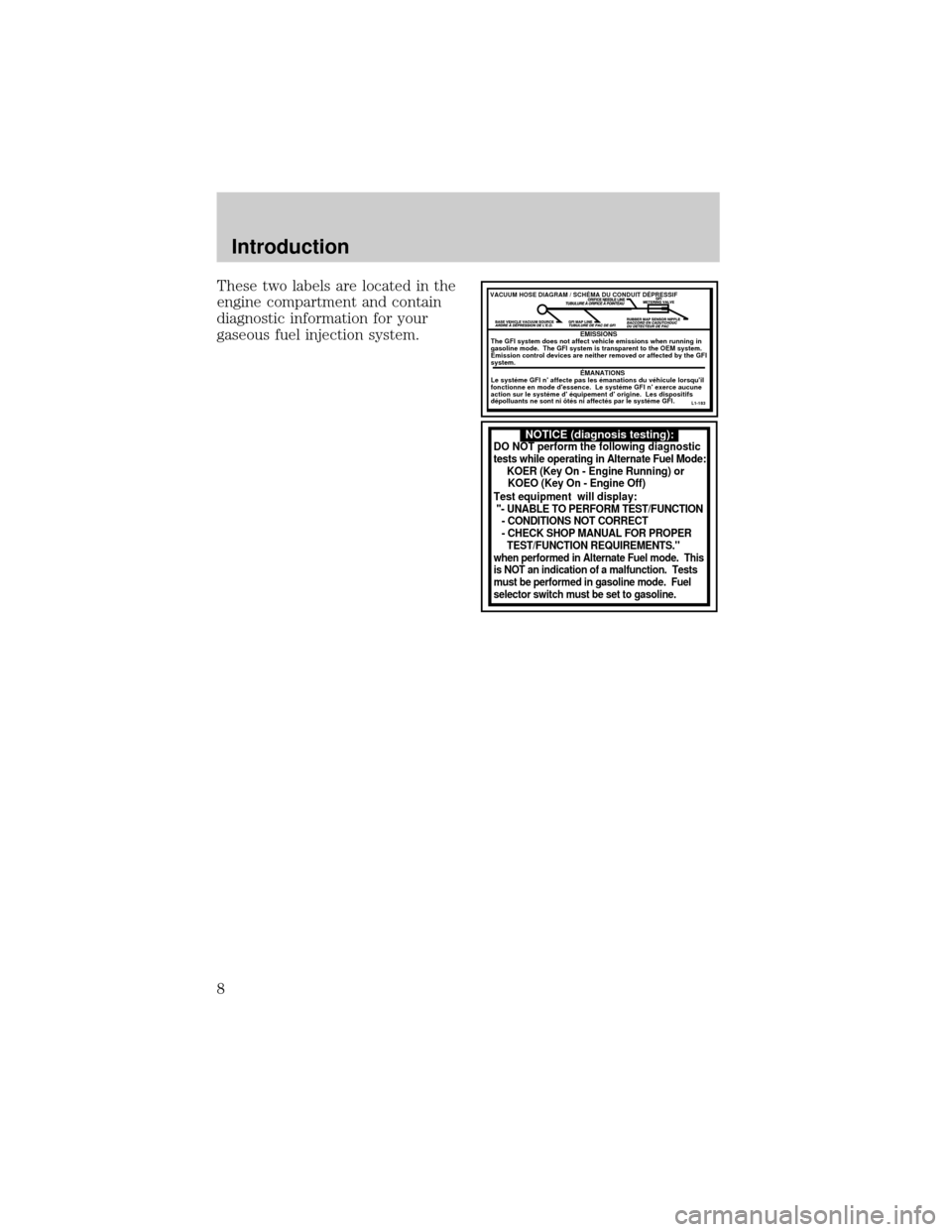
These two labels are located in the
engine compartment and contain
diagnostic information for your
gaseous fuel injection system.
NOTICE (diagnosis testing):DO NOT perform the following diagnostic
tests while operating in Alternate Fuel Mode:
KOER (Key On - Engine Running) or
KOEO (Key On - Engine Off)
Test equipment will display:
"- UNABLE TO PERFORM TEST/FUNCTION
- CONDITIONS NOT CORRECT
- CHECK SHOP MANUAL FOR PROPER
TEST/FUNCTION REQUIREMENTS."
when performed in Alternate Fuel mode. This
is NOT an indication of a malfunction. Tests
must be performed in gasoline mode. Fuel
selector switch must be set to gasoline.
VACUUM HOSE DIAGRAM / SCHÉMA DU CONDUIT DÉPRESSIF
EMISSIONS
The GFI system does not affect vehicle emissions when running in
gasoline mode. The GFI system is transparent to the OEM system.
Emission control devices are neither removed or affected by the GFI
system.
ÉMANATIONS
Le systéme GFI n' affecte pas les émanations du véhicule lorsqu'il
fonctionne en mode d'essence. Le systéme GFI n' exerce aucune
action sur le systéme d' équipement d' origine. Les dispositifs
dépolluants ne sont ni ôtés ni affectés par le systéme GFI.
L1-183
Introduction
8
Page 9 of 32
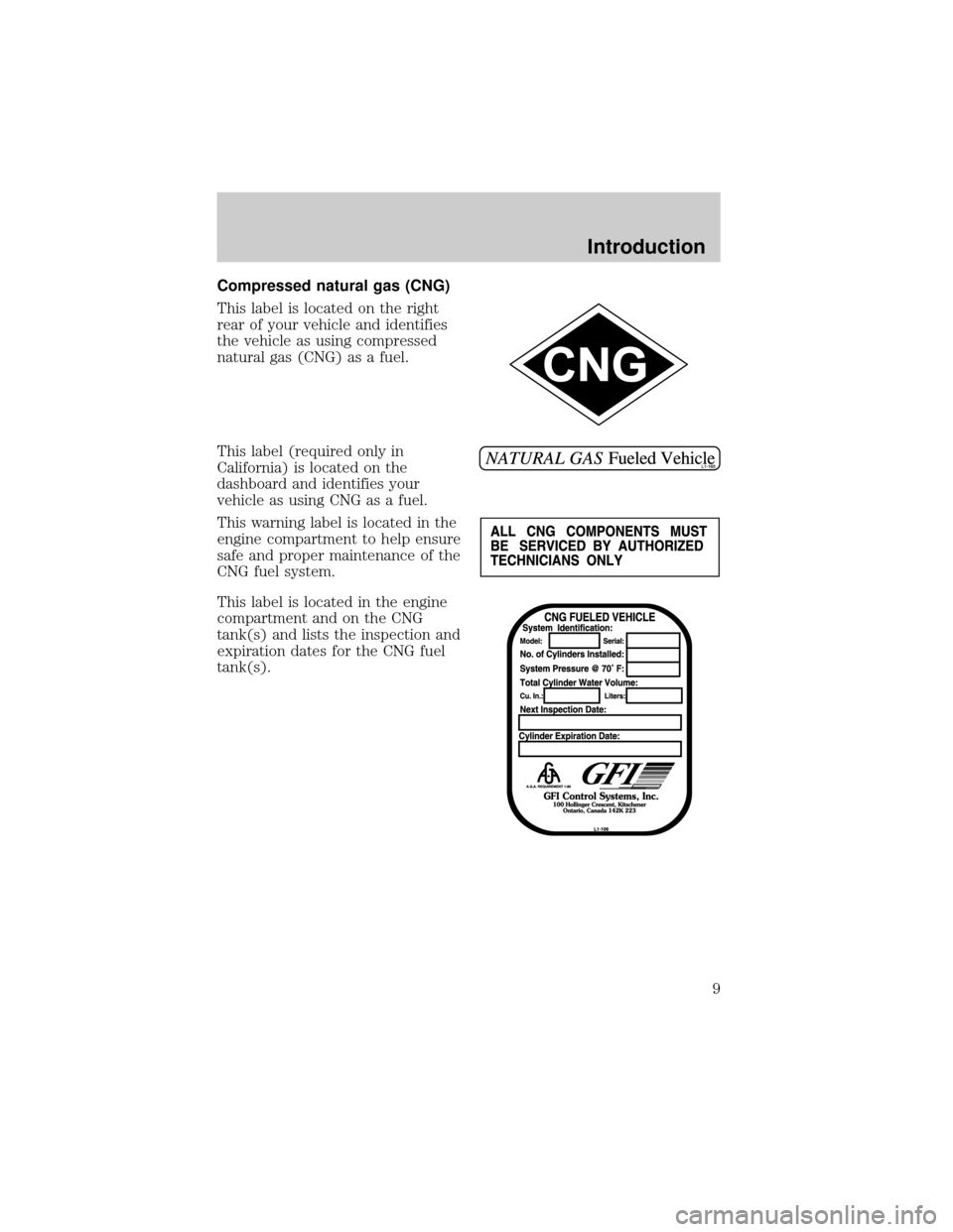
Compressed natural gas (CNG)
This label is located on the right
rear of your vehicle and identifies
the vehicle as using compressed
natural gas (CNG) as a fuel.
This label (required only in
California) is located on the
dashboard and identifies your
vehicle as using CNG as a fuel.
This warning label is located in the
engine compartment to help ensure
safe and proper maintenance of the
CNG fuel system.
This label is located in the engine
compartment and on the CNG
tank(s) and lists the inspection and
expiration dates for the CNG fuel
tank(s).
Introduction
9
Page 10 of 32
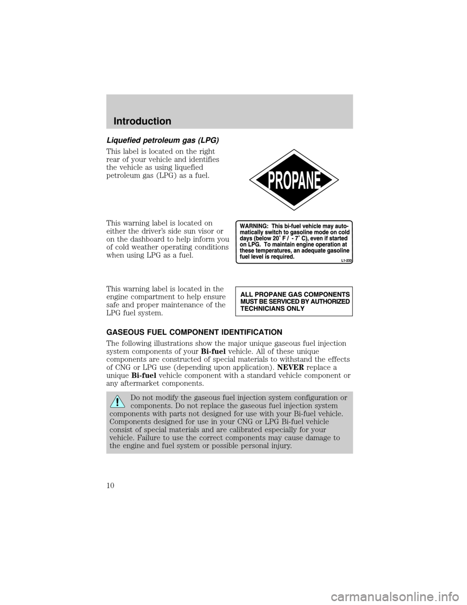
Liquefied petroleum gas (LPG)
This label is located on the right
rear of your vehicle and identifies
the vehicle as using liquefied
petroleum gas (LPG) as a fuel.
This warning label is located on
either the driver's side sun visor or
on the dashboard to help inform you
of cold weather operating conditions
when using LPG as a fuel.
This warning label is located in the
engine compartment to help ensure
safe and proper maintenance of the
LPG fuel system.
GASEOUS FUEL COMPONENT IDENTIFICATION
The following illustrations show the major unique gaseous fuel injection
system components of yourBi-fuelvehicle. All of these unique
components are constructed of special materials to withstand the effects
of CNG or LPG use (depending upon application).NEVERreplace a
uniqueBi-fuelvehicle component with a standard vehicle component or
any aftermarket components.
Do not modify the gaseous fuel injection system configuration or
components. Do not replace the gaseous fuel injection system
components with parts not designed for use with your Bi-fuel vehicle.
Components designed for use in your CNG or LPG Bi-fuel vehicle
consist of special materials and are calibrated especially for your
vehicle. Failure to use the correct components may cause damage to
the engine and fuel system or possible personal injury.
Introduction
10
Page 11 of 32
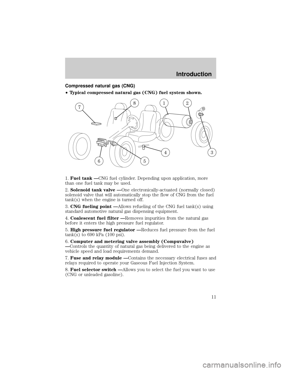
Compressed natural gas (CNG)
²Typical compressed natural gas (CNG) fuel system shown.
1.Fuel tank ÐCNG fuel cylinder. Depending upon application, more
than one fuel tank may be used.
2.Solenoid tank valve ÐOne electronically-actuated (normally closed)
solenoid valve that will automatically stop the flow of CNG from the fuel
tank(s) when the engine is turned off.
3.CNG fueling point ÐAllows refueling of the CNG fuel tank(s) using
standard automotive natural gas dispensing equipment.
4.Coalescent fuel filter ÐRemoves impurities from the natural gas
before it enters the high pressure fuel regulator.
5.High pressure fuel regulator ÐReduces fuel pressure from the fuel
tank(s) to 690 kPa (100 psi).
6.Computer and metering valve assembly (Compuvalve)
ÐControls the quantity of natural gas being delivered to the engine as
vehicle speed and load requirements demand.
7.Fuse and relay module ÐContains the necessary electrical fuses and
relays required to operate your Gaseous Fuel Injection System.
8.Fuel selector switch ÐAllows you to select the fuel you want to use
(CNG or unleaded gasoline).
Introduction
11
Page 12 of 32
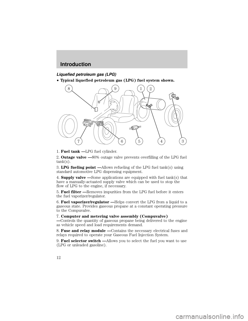
Liquefied petroleum gas (LPG)
²Typical liquefied petroleum gas (LPG) fuel system shown.
1.Fuel tank ÐLPG fuel cylinder.
2.Outage valve Ð80% outage valve prevents overfilling of the LPG fuel
tank(s).
3.LPG fueling point ÐAllows refueling of the LPG fuel tank(s) using
standard automotive LPG dispensing equipment.
4.Supply valve ÐSome applications are equipped with fuel tank(s) that
have a manually-actuated supply valve which can be used to stop the
flow of LPG to the engine, if necessary.
5.Fuel filter ÐRemoves impurities from the LPG fuel before it enters
the fuel vaporizer/regulator.
6.Fuel vaporizer/regulator ÐHelps convert the LPG from a liquid to a
gaseous state. Provides gaseous propane at a constant operating pressure
to the Compuvalve.
7.Computer and metering valve assembly (Compuvalve)
ÐControls the quantity of gaseous propane being delivered to the engine
as vehicle speed and load requirements demand.
8.Fuse and relay module ÐContains the necessary electrical fuses and
relays required to operate your Gaseous Fuel Injection System.
9.Fuel selector switch ÐAllows you to select the fuel you want to use
(LPG or unleaded gasoline).
192
35467
8
Introduction
12
Page 13 of 32
FUEL SELECTOR SWITCH
This booklet supplements your Owner's Guide and is part of the owner's
portfolio. It describes the operation of yourBi-fuelvehicle and how it
differs from a standard gasoline powered vehicle. Therefore it is very
important that you read this guide and thoroughly familiarize yourself
and others operating the vehicle with this information.
The fuel selector switch allows you to select which fuel yourBi-fuel
vehicle will operate on.
The fuel selector switch only operates when the vehicle is at a
stop with the ignition in the OFF position. If the fuel selector
switch is moved while the vehicle is running, the gaseous fuel
injection system will NOT automatically change fuel modes and
no damage to the vehicle will occur. Except for vehicles equipped
with the LPG extended-range fuel tank system, the fuel selector
switch will allow you to switch between the two LPG fuel tanks
while you are driving.
Prior to starting the vehicle (with the ignition in the OFF position),
determine which fuel you would like to use and press the rocker switch
located on the dash panel.
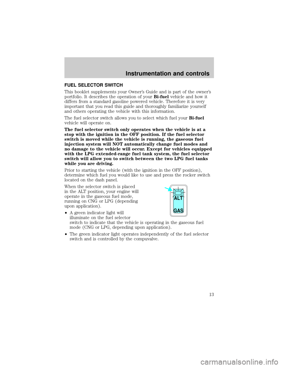
When the selector switch is placed
in the ALT position, your engine will
operate in the gaseous fuel mode,
running on CNG or LPG (depending
upon application).
²A green indicator light will
illuminate on the fuel selector
switch to indicate that the vehicle is operating in the gaseous fuel
mode (CNG or LPG, depending upon application).
²The green indicator light operates independently of the fuel selector
switch and is controlled by the compuvalve.
ALT
GAS
Instrumentation and controls
13
Page 14 of 32
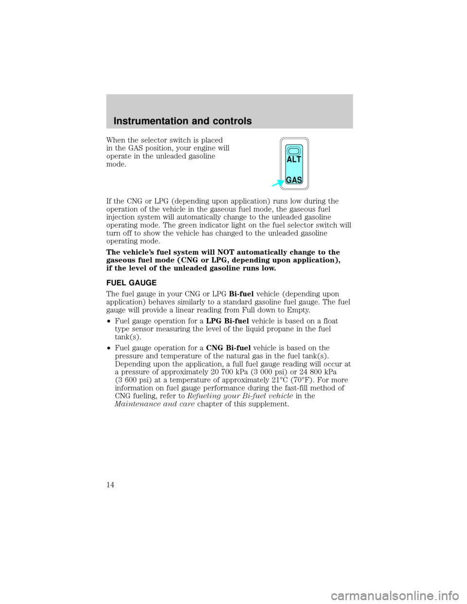
When the selector switch is placed
in the GAS position, your engine will
operate in the unleaded gasoline
mode.
If the CNG or LPG (depending upon application) runs low during the
operation of the vehicle in the gaseous fuel mode, the gaseous fuel
injection system will automatically change to the unleaded gasoline
operating mode. The green indicator light on the fuel selector switch will
turn off to show the vehicle has changed to the unleaded gasoline
operating mode.
The vehicle's fuel system will NOT automatically change to the
gaseous fuel mode (CNG or LPG, depending upon application),
if the level of the unleaded gasoline runs low.
FUEL GAUGE
The fuel gauge in your CNG or LPGBi-fuelvehicle (depending upon
application) behaves similarly to a standard gasoline fuel gauge. The fuel
gauge will provide a linear reading from Full down to Empty.
²Fuel gauge operation for aLPG Bi-fuelvehicle is based on a float
type sensor measuring the level of the liquid propane in the fuel
tank(s).
²Fuel gauge operation for aCNG Bi-fuelvehicle is based on the
pressure and temperature of the natural gas in the fuel tank(s).
Depending upon the application, a full fuel gauge reading will occur at
a pressure of approximately 20 700 kPa (3 000 psi) or 24 800 kPa
(3 600 psi) at a temperature of approximately 21ÉC (70ÉF). For more
information on fuel gauge performance during the fast-fill method of
CNG fueling, refer toRefueling your Bi-fuel vehiclein the
Maintenance and carechapter of this supplement.
ALT
GAS
Instrumentation and controls
14