2002 FORD EXPLORER ignition
[x] Cancel search: ignitionPage 196 of 312
Special loading instructions for owners of pickup trucks and
utility-type vehicles
For important information regarding safe operation of this type
of vehicle, see thePreparing to drive your vehiclesection in
theDrivingchapter of this owner guide.
Loaded vehicles, with a higher center of gravity, may handle
differently than unloaded vehicles. Extra precautions, such as
slower speeds and increased stopping distance, should be taken when
driving a heavily loaded vehicle.
Your vehicle has the capability to haul more cargo and people than most
passenger cars. Depending upon the type and placement of the load,
hauling cargo and people may raise the center of gravity of the vehicle.
Calculating the load your vehicle can carry/tow
1. Use the appropriate maximum gross combined weight rating (GCWR)
chart to find the maximum GCWR for your type engine and rear axle
ratio.
2. Weigh your vehicle as you customarily operate the vehicle without
cargo. To obtain correct weights, try taking your vehicle to a shipping
company or an inspection station for trucks.
3. Subtract your loaded vehicle weight from the maximum GCWR on the
following charts. This is the maximum trailer weight your vehicle can tow
and must fall below the maximum shown under maximum trailer weight
on the chart.
DRIVING THROUGH WATER
Do not drive quickly through standing water, especially if the depth is
unknown. Traction or brake capability may be limited and if the ignition
system gets wet, your engine may stall. Water may also enter your
engine's air intake and severely damage your engine.
If driving through deep or standing water is unavoidable, proceed very
slowly. Never drive through water that is higher than the bottom of the
hubs (for trucks) or the bottom of the wheel rims (for cars).
Once through the water, always try the brakes. Wet brakes do not stop the
vehicle as effectively as dry brakes. Drying can be improved by moving
your vehicle slowly while applying light pressure on the brake pedal.
Driving
196
Page 206 of 312
Roadside coverage beyond basic warranty
In the United States, you may purchase additional roadside assistance
coverage beyond this period through the Ford Auto Club by contacting
your Ford or Lincoln Mercury dealer.
Similarly in Canada, you may purchase additional coverage beyond the
basic coverage period by consulting the Ford Roadside Assistance Club
brochure or by calling 1±877±294±CLUB (1±877±294±2582).
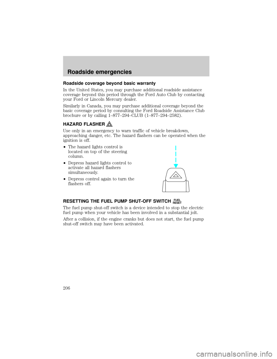
HAZARD FLASHER
Use only in an emergency to warn traffic of vehicle breakdown,
approaching danger, etc. The hazard flashers can be operated when the
ignition is off.
²The hazard lights control is
located on top of the steering
column.
²Depress hazard lights control to
activate all hazard flashers
simultaneously.
²Depress control again to turn the
flashers off.
RESETTING THE FUEL PUMP SHUT-OFF SWITCH
FUEL
RESET
The fuel pump shut-off switch is a device intended to stop the electric
fuel pump when your vehicle has been involved in a substantial jolt.
After a collision, if the engine cranks but does not start, the fuel pump
shut-off switch may have been activated.
Roadside emergencies
206
Page 207 of 312

The fuel pump shut-off switch is
located in the passenger's foot well,
by the kick panel.
Use the following procedure to reset the fuel pump shut-off switch.
1. Turn the ignition to the OFF position.
2. Check the fuel system for leaks.
3. If no fuel leak is apparent, reset the fuel pump shut-off switch by
pushing in on the reset button.
4. Turn the ignition to the ON position. Pause for a few seconds and
return the key to the OFF position.
5. Make a further check for leaks in the fuel system.
FUSES AND RELAYS
Fuses
If electrical components in the
vehicle are not working, a fuse may
have blown. Blown fuses are
identified by a broken wire within
the fuse. Check the appropriate
fuses before replacing any electrical
components.
15
Roadside emergencies
207
Page 214 of 312

The high-current fuses are coded as follows:
Fuse/Relay
LocationFuse Amp
RatingPower Distribution Box
Description
1 60A** PJB
2 20A** Door Locks
3 20A** GCC Pusher Fan (export only)
4 30A** Heated Backlight
5 40A** ABS
6 60A** Circuit Breaker
7 20A** Power Point #2
8 Ð Not Used
9 20A** Power Point #1
10 20A** ABS Module
11 40A** PTEC
12 50A** Ignition Relay
13 30A** Trailer Tow Battery
14 10A* Fog Lamps
15 5A* Memory
16 15A* Headlamp Switch
17 20A*4 x 4 (v-batt 2)
18 20A*4 x 4 (v-batt 1)
19 20A** High Beam Relay
20 30A** Electric Brake
21 Ð Not Used
22 20A** Autolmap; Low Beam
23 30A** Ignition Switch
24 10A* Rear Fog Lamps
25 20A* Security Module (horns)
26 15A* Fuel Pump
27 20A* Trailer Tow Lamps
28 10A* Daytime Running Lamps (DRL)
29 60A** PJB
30 Ð Not Used
31 Ð Not Used
32 Ð Not Used
33 30A** Auxiliary Blower Motor
Roadside emergencies
214
Page 215 of 312

Fuse/Relay
LocationFuse Amp
RatingPower Distribution Box
Description
34 30A** Power Seats
35 Ð Not Used
36 40A** Blower Motor
37 15A* A/C Clutch
38 15A* Coil On Plug
39 15A* High Beam
40 15A* PTEC Power
41 15A* HEGO, UMV, CMS, PTEC
42 10A* Right Low Beam
43 10A* Left Low Beam
44 10A* High Beam Relay
45 7.5A* Right High Beam (export only)
46 15A* Injectors
47 Ð Daytime Running Lamps Relay,
GCC Pusher Fan (export)
48 Ð Fuel Pump Relay
49 Ð High Beam Relay
50 Ð Fog Lamp Relay
51 Ð Autolamp Relay
52 Ð A/C Clutch Relay
53 Ð Park Lamp Relay (export)
54 Ð Wiper Run / Park Relay
55 Ð Blower Motor Relay
56 Ð Starter Relay
57 Ð PTEC Relay
58 Ð Ignition Relay
59 Ð Wiper High/Low Relay
60 Ð PCM Diode
61 Ð A/C Clutch Diode
67 30A CB Delayed accessory
* Mini Fuses ** Maxi Cartridge Fuses
Roadside emergencies
215
Page 264 of 312
If you have run out of fuel:
²You may need to cycle the ignition from OFF to ON several times after
refueling, to allow the fuel system to pump the fuel from the tank to
the engine.
²Your ªCheck Engineº indicator may come on. For more information on
the ªCheck Engineº indicator, refer to theInstrumentationchapter.
Fuel Filler Cap
Your fuel tank filler cap has an indexed design with a 1/8 turn on/off
feature.
When fueling your vehicle:
1. Turn the engine off.
2. Carefully turn the filler cap counterclockwise 1/8 of a turn until it
stops.
3. Pull to remove the cap from the fuel filler pipe.
4. To install the cap, align the tabs on the cap with the notches on the
filler pipe.
5. Turn the filler cap clockwise 1/8 of a turn until it stops.
If the ªCheck Fuel Capº indicator comes on and stays on after you start
the engine, the fuel filler cap may not be properly installed. Turn off the
engine, remove the fuel filler cap, align the cap properly and reinstall it.
If you must replace the fuel filler cap, replace it with a fuel filler
cap that is designed for your vehicle. The customer warranty may
be void for any damage to the fuel tank or fuel system if the
correct genuine Ford or Motorcraft fuel filler cap is not used.
The fuel system may be under pressure. If the fuel filler cap is
venting vapor or if you hear a hissing sound, wait until it stops
before completely removing the fuel filler cap. Otherwise, fuel may
spray out and injure you or others.
If you do not use the proper fuel filler cap, excessive pressure or
vacuum in the fuel tank may damage the fuel system or cause
the fuel cap to disengage in a collision, which may result in possible
personal injury.
Maintenance and care
264
Page 265 of 312
Fuel Filter
For fuel filter replacement, see your dealer or a qualified service
technician. Refer to the scheduled maintenance guide for the appropriate
intervals for changing the fuel filter.
Replace the fuel filter with an authorized Motorcraft part. The
customer warranty may be void for any damage to the fuel system
if an authorized Motorcraft fuel filter is not used.
ESSENTIALS OF GOOD FUEL ECONOMY
Measuring techniques
Your best source of information about actual fuel economy is you, the
driver. You must gather information as accurately and consistently as
possible. Fuel expense, frequency of fillups or fuel gauge readings are
NOT accurate as a measure of fuel economy. We do not recommend
taking fuel economy measurements during the first 1 600 km (1 000
miles) of driving (engine break-in period). You will get a more accurate
measurement after 3 000 km±5 000 km (2 000 miles-3 000 miles).
Filling the tank
The advertised fuel capacity of the fuel tank on your vehicle is equal to
the rated refill capacity of the fuel tank as listed in theRefill Capacities
section of theCapacities and specificationschapter.
The advertised capacity is the amount of the indicated capacity and the
empty reserve combined. Indicated capacity is the difference in the
amount of fuel in a full tank and a tank when the fuel gauge indicates
empty. Empty reserve is the small amount of fuel remaining in the fuel
tank after the fuel gauge indicates empty.
The amount of usable fuel in the empty reserve varies and should
not be relied upon to increase driving range. When refueling your
vehicle after the fuel gauge indicates empty, you might not be
able to refuel the full amount of the advertised capacity of the
fuel tank due to the empty reserve still present in the tank.
For consistent results when filling the fuel tank:
²Turn the engine/ignition switch to the off position prior to refueling,
an error in the reading will result if the engine is left running.
²Use the same filling rate setting (low Ð medium Ð high) each time
the tank is filled.
Maintenance and care
265
Page 268 of 312
²Using fuel blended with alcohol may lower fuel economy.
²Fuel economy may decrease with lower temperatures during the first
12±16 km (8±10 miles) of driving.
²Driving on flat terrain offers improved fuel economy as compared to
driving on hilly terrain.
²Transmissions give their best fuel economy when operated in the top
cruise gear and with steady pressure on the gas pedal.
²Four-wheel-drive operation (if equipped) is less fuel efficient than
two-wheel-drive operation.
²Close windows for high speed driving.
EPA window sticker
Every new vehicle should have the EPA window sticker. Contact your
dealer if the window sticker is not supplied with your vehicle. The EPA
window sticker should be your guide for the fuel economy comparisons
with other vehicles.
It is important to note the box in the lower left corner of the window
sticker. These numbers represent the Range of L/100 km (MPG)
expected on the vehicle under optimum conditions. Your fuel economy
may vary depending upon the method of operation and conditions.
EMISSION CONTROL SYSTEM
Your vehicle is equipped with various emission control components and a
catalytic converter which will enable your vehicle to comply with
applicable exhaust emission standards. To make sure that the catalytic
converter and other emission control components continue to work
properly:
²Use only the specified fuel listed.
²Avoid running out of fuel.
²Do not turn off the ignition while your vehicle is moving, especially at
high speeds.
²Have the items listed in your scheduled maintenance guide performed
according to the specified schedule.
The scheduled maintenance items listed in the scheduled maintenance
guide are essential to the life and performance of your vehicle and to its
emissions system.
Maintenance and care
268