2002 DODGE RAM drain bolt
[x] Cancel search: drain boltPage 1359 of 2255
(5) Vacuum leak ? Check condition of banjo fit-
tings, banjo bolts, and sealing washers. If leaks are
not present, a leak exists within VP-44 pump.
Replacement of VP-44 requires authorization.DIAGNOSIS AND TESTING - AIR IN FUEL
SYSTEM
Air will enter the fuel system whenever fuel supply
lines, separator filters, injection pump, high-pressure
lines or injectors are removed or disconnected. Air
trapped in the fuel system can result in hard start-
ing, a rough running engine, engine misfire, low
power, excessive smoke and fuel knock. After service
is performed, air must be bled from the system
before starting the engine.
Inspect the fuel system from the fuel transfer
pump to the injectors for loose connections. Leaking
fuel is an indicator of loose connections or defective
seals. Air can also enter the fuel system between the
fuel tank and the transfer pump. Inspect the fuel
tank and fuel lines for damage that might allow air
into the system.
For air bleeding, refer to the Air Bleed Procedure.
DIAGNOSIS AND TESTING - FUEL SUPPLY
RESTRICTIONS
LOW-PRESSURE LINES
Fuel supply line restrictions or a defective fuel
transfer pump can cause starting problems and pre-
vent engine from accelerating. The starting problems
include; low power and/or white fog like exhaust.
Test all fuel supply lines for restrictions or block-
age. Flush or replace as necessary. Bleed fuel system
of air once a fuel supply line has been replaced. Refer
to Air Bleed Procedure for procedures.
To test for fuel line restrictions, a vacuum restric-
tion test may be performed. Refer to Fuel Transfer
Pump Pressure Test.
HIGH-PRESSURE LINES
Restricted (kinked or bent) high-pressure lines can
cause starting problems, poor engine performance,
engine mis-fire and white smoke from exhaust.
Examine all high-pressure lines for any damage.
Each radius on each high-pressure line must be
smooth and free of any bends or kinks.
Replace damaged, restricted or leaking high-pres-
sure fuel lines with correct replacement line.
CAUTION: All high-pressure fuel lines must be
clamped securely in place in holders. Lines cannot
contact each other or other components. Do not
attempt to weld high-pressure fuel lines or to repair
lines that are damaged. If line is kinked or bent, it
must be replaced. Use only recommended lines
when replacement of high-pressure fuel line is nec-
essary.
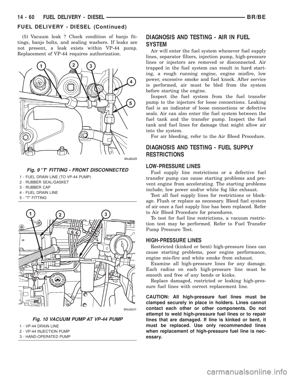
Fig. 9(T(FITTING - FRONT DISCONNECTED
1 - FUEL DRAIN LINE (TO VP-44 PUMP)
2 - RUBBER SEAL/GASKET
3 - RUBBER CAP
4 - FUEL DRAIN LINE
5-9T9FITTING
Fig. 10 VACUUM PUMP AT VP-44 PUMP
1 - VP-44 DRAIN LINE
2 - VP-44 INJECTION PUMP
3 - HAND-OPERATED PUMP
14 - 60 FUEL DELIVERY - DIESELBR/BE
FUEL DELIVERY - DIESEL (Continued)
Page 1360 of 2255
STANDARD PROCEDURE
STANDARD PROCEDURES - WATER DRAINING
AT FUEL FILTER
Refer to Fuel Filter/Water Separator removal/in-
stallation for procedures.
STANDARD PROCEDURES - CLEANING FUEL
SYSTEM PARTS
CAUTION: Cleanliness cannot be overemphasized
when handling or replacing diesel fuel system com-
ponents. This especially includes the fuel injectors,
high-pressure fuel lines and fuel injection pump.
Very tight tolerances are used with these parts. Dirt
contamination could cause rapid part wear and pos-
sible plugging of fuel injector nozzle tip holes. This
in turn could lead to possible engine misfire.
Always wash/clean any fuel system component
thoroughly before disassembly and then air dry.
Cap or cover any open part after disassembly.
Before assembly, examine each part for dirt, grease
or other contaminants and clean if necessary. When
installing new parts, lubricate them with clean
engine oil or clean diesel fuel only.
STANDARD PROCEDURE - AIR BLEED
A certain amount of air becomes trapped in the
fuel system when fuel system components on the
supply and/or high-pressure side are serviced or
replaced. Primary air bleeding is accomplished using
the electric fuel transfer (lift) pump. If the vehicle
has been allowed to run completely out of fuel, the
fuel injectors must also be bled as the fuel injection
pumpis notself-bleeding (priming).
Servicing or replacing components on the fuel
return side will not require air bleeding.
WARNING: DO NOT BLEED AIR FROM THE FUEL
SYSTEM OF A HOT ENGINE.
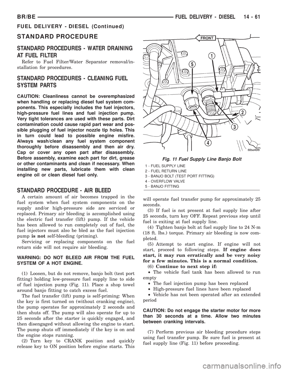
(1) Loosen, but do not remove, banjo bolt (test port
fitting) holding low-pressure fuel supply line to side
of fuel injection pump (Fig. 11). Place a shop towel
around banjo fitting to catch excess fuel.
The fuel transfer (lift) pump is self-priming: When
the key is first turned on (without cranking engine),
the pump operates for approximately 2 seconds and
then shuts off. The pump will also operate for up to
25 seconds after the starter is quickly engaged, and
then disengaged without allowing the engine to start.
The pump shuts off immediately if the key is on and
the engine stops running.
(2) Turn key to CRANK position and quickly
release key to ON position before engine starts. Thiswill operate fuel transfer pump for approximately 25
seconds.
(3) If fuel is not present at fuel supply line after
25 seconds, turn key OFF. Repeat previous step until
fuel is exiting at fuel supply line.
(4) Tighten banjo bolt at fuel supply line to 24 N´m
(18 ft. lbs.) torque. Primary air bleeding is now com-
pleted.
(5) Attempt to start engine. If engine will not
start, proceed to following steps.If engine does
start, it may run erratically and be very noisy
for a few minutes. This is a normal condition.
(6)Continue to next step if:
²The vehicle fuel tank has been allowed to run
empty
²The fuel injection pump has been replaced
²High-pressure fuel lines have been replaced
²Vehicle has not been operated after an extended
period
CAUTION: Do not engage the starter motor for more
than 30 seconds at a time. Allow two minutes
between cranking intervals.
(7) Perform previous air bleeding procedure steps
using fuel transfer pump. Be sure fuel is present at
fuel supply line (Fig. 11) before proceeding.
Fig. 11 Fuel Supply Line Banjo Bolt
1 - FUEL SUPPLY LINE
2 - FUEL RETURN LINE
3 - BANJO BOLT (TEST PORT FITTING)
4 - OVERFLOW VALVE
5 - BANJO FITTING
BR/BEFUEL DELIVERY - DIESEL 14 - 61
FUEL DELIVERY - DIESEL (Continued)
Page 1386 of 2255
(2) Thoroughly clean area around transfer pump
and fuel lines of any contamination.
(3) Remove starter motor. Refer to Starter Remov-
al/Installation in 8, Starting System for procedures.
(4) Place a drain pan below the pump.
(5) Disconnect fuel line quick-connect fitting at
fuel supply line (Fig. 64) at rear of pump.
(6) Remove support bracket bolt at top of pump
(Fig. 64).
(7) Remove front and rear banjo bolts at pump
(Fig. 64).
(8) Disconnect electrical connector at side of pump
(Fig. 64).
(9) Remove three pump bracket nuts (Fig. 64) and
remove pump from vehicle.
INSTALLATION
The fuel transfer pump (fuel lift pump) is located
on left side of engine, below and rearward of fuel fil-
ter (Fig. 64).
(1) Install new gaskets to fuel supply line/support
bracket and banjo bolt at rear of pump. Install line
and banjo bolt to pump.Do nottighten banjo bolt at
this time.
(2) Install new gaskets to fuel line and banjo bolt
at front of pump.
(3) Position 3 pump studs into pump mounting
bracket and install 3 nuts.Do nottighten nuts at
this time.
(4) Install support bracket bolt (Fig. 64).Do not
tighten bolt at this time.
(5) Tighten 3 pump nuts to 12 N´m (9 ft. lbs.)
torque.
(6) Tighten both banjo bolts to 24 N´m (18 ft. lbs.)
torque.
(7) Tighten support bracket bolt 12 N´m (9 ft. lbs.)
torque.
(8) Connect electrical connector to pump (Fig. 64).
(9) Connect fuel line quick-connect fitting to fuel
supply line at rear of pump.
(10) Install starter motor. Refer to Starter Remov-
al/Installation in 8, Starting for procedures.
(11) Connect both negative battery cables at both
batteries.
(12) Bleed air at fuel supply line at side of fuel
injection pump. Refer to the Air Bleed Procedure.
(13) Start engine and check for leaks.
OVERFLOW VALVE
DESCRIPTION
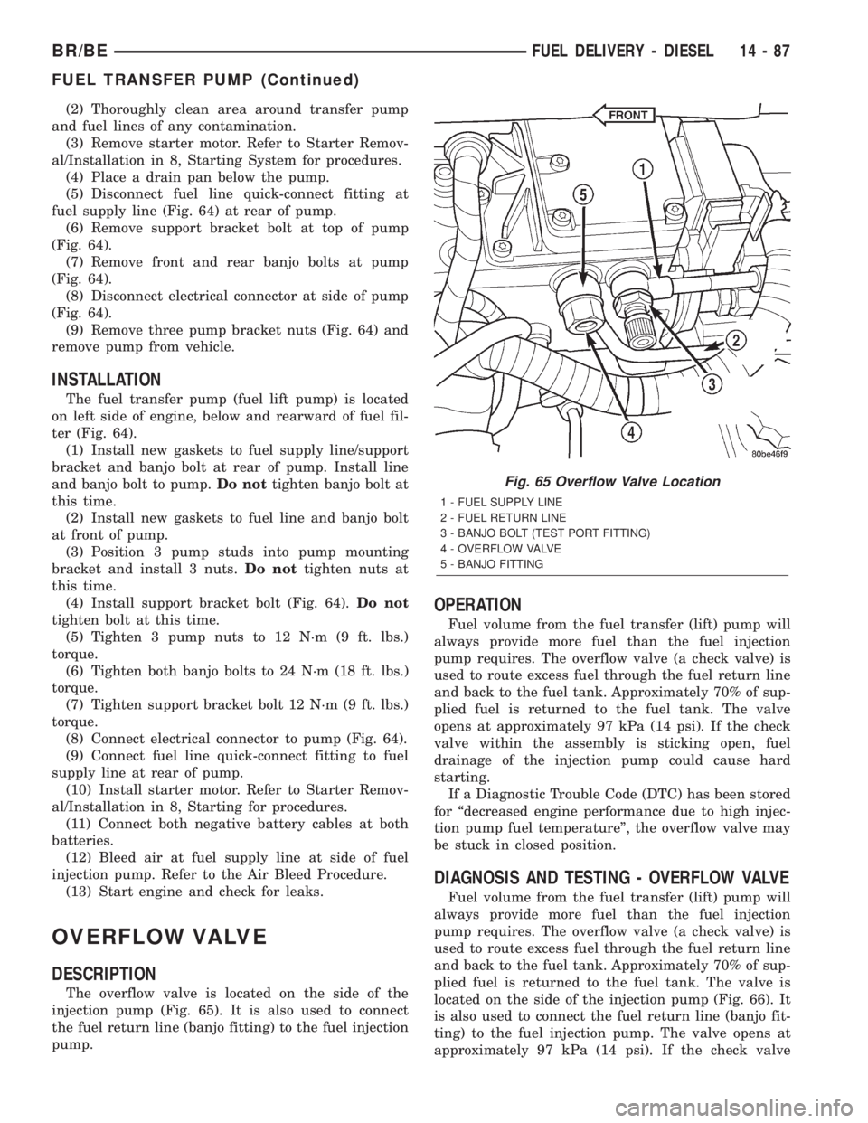
The overflow valve is located on the side of the
injection pump (Fig. 65). It is also used to connect
the fuel return line (banjo fitting) to the fuel injection
pump.
OPERATION
Fuel volume from the fuel transfer (lift) pump will
always provide more fuel than the fuel injection
pump requires. The overflow valve (a check valve) is
used to route excess fuel through the fuel return line
and back to the fuel tank. Approximately 70% of sup-
plied fuel is returned to the fuel tank. The valve
opens at approximately 97 kPa (14 psi). If the check
valve within the assembly is sticking open, fuel
drainage of the injection pump could cause hard
starting.
If a Diagnostic Trouble Code (DTC) has been stored
for ªdecreased engine performance due to high injec-
tion pump fuel temperatureº, the overflow valve may
be stuck in closed position.
DIAGNOSIS AND TESTING - OVERFLOW VALVE
Fuel volume from the fuel transfer (lift) pump will
always provide more fuel than the fuel injection
pump requires. The overflow valve (a check valve) is
used to route excess fuel through the fuel return line
and back to the fuel tank. Approximately 70% of sup-
plied fuel is returned to the fuel tank. The valve is
located on the side of the injection pump (Fig. 66). It
is also used to connect the fuel return line (banjo fit-
ting) to the fuel injection pump. The valve opens at
approximately 97 kPa (14 psi). If the check valve
Fig. 65 Overflow Valve Location
1 - FUEL SUPPLY LINE
2 - FUEL RETURN LINE
3 - BANJO BOLT (TEST PORT FITTING)
4 - OVERFLOW VALVE
5 - BANJO FITTING
BR/BEFUEL DELIVERY - DIESEL 14 - 87
FUEL TRANSFER PUMP (Continued)
Page 1388 of 2255
WATER IN FUEL SENSOR
DESCRIPTION
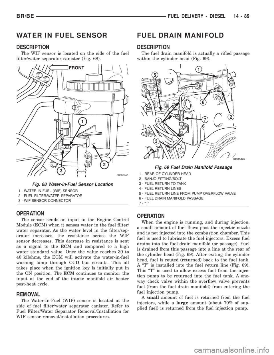
The WIF sensor is located on the side of the fuel
filter/water separator canister (Fig. 68).
OPERATION
The sensor sends an input to the Engine Control
Module (ECM) when it senses water in the fuel filter/
water separator. As the water level in the filter/sep-
arator increases, the resistance across the WIF
sensor decreases. This decrease in resistance is sent
as a signal to the ECM and compared to a high
water standard value. Once the value reaches 30 to
40 kilohms, the ECM will activate the water-in-fuel
warning lamp through CCD bus circuits. This all
takes place when the ignition key is initially put in
the ON position. The ECM continues to monitor the
input at the end of the intake manifold air heater
post-heat cycle.
REMOVAL
The Water-In-Fuel (WIF) sensor is located at the
side of fuel filter/water separator canister. Refer to
Fuel Filter/Water Separator Removal/Installation for
WIF sensor removal/installation procedures.
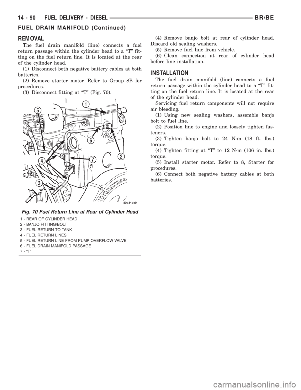
FUEL DRAIN MANIFOLD
DESCRIPTION
The fuel drain manifold is actually a rifled passage
within the cylinder head (Fig. 69).
OPERATION
When the engine is running, and during injection,
a small amount of fuel flows past the injector nozzle
and is not injected into the combustion chamber. This
fuel is used to lubricate the fuel injectors. Excess fuel
drains into the fuel drain manifold (or passage). Fuel
is drained from this passage into a line at the rear of
the cylinder head (Fig. 69). After exiting the cylinder
head, fuel is routed (returned) back to the fuel tank.
A ªTº is installed into the fuel return line (Fig. 69).
This ªTº is used to allow excess fuel from the injec-
tion pump to be returned into the fuel tank. A one-
way check valve within the overflow valve prevents
fuel (from the fuel drain manifold) from entering the
fuel injection pump.
Asmallamount of fuel is returned from the fuel
injectors, while alargeamount (about 70% of sup-
plied fuel) is returned from the fuel injection pump.
Fig. 68 Water-in-Fuel Sensor Location
1 - WATER-IN-FUEL (WIF) SENSOR
2 - FUEL FILTER/WATER SEPARATOR
3 - WIF SENSOR CONNECTOR
Fig. 69 Fuel Drain Manifold Passage
1 - REAR OF CYLINDER HEAD
2 - BANJO FITTING/BOLT
3 - FUEL RETURN TO TANK
4 - FUEL RETURN LINES
5 - FUEL RETURN LINE FROM PUMP OVERFLOW VALVE
6 - FUEL DRAIN MANIFOLD PASSAGE
7 - ªTº
BR/BEFUEL DELIVERY - DIESEL 14 - 89
Page 1389 of 2255
REMOVAL
The fuel drain manifold (line) connects a fuel
return passage within the cylinder head to a ªTº fit-
ting on the fuel return line. It is located at the rear
of the cylinder head.
(1) Disconnect both negative battery cables at both
batteries.
(2) Remove starter motor. Refer to Group 8B for
procedures.
(3) Disconnect fitting at ªTº (Fig. 70).(4) Remove banjo bolt at rear of cylinder head.
Discard old sealing washers.
(5) Remove fuel line from vehicle.
(6) Clean connection at rear of cylinder head
before line installation.
INSTALLATION
The fuel drain manifold (line) connects a fuel
return passage within the cylinder head to a ªTº fit-
ting on the fuel return line. It is located at the rear
of the cylinder head.
Servicing fuel return components will not require
air bleeding.
(1) Using new sealing washers, assemble banjo
bolt to fuel line.
(2) Position line to engine and loosely tighten fas-
teners.
(3) Tighten banjo bolt to 24 N´m (18 ft. lbs.)
torque.
(4) Tighten fitting at ªTº to 12 N´m (106 in. lbs.)
torque.
(5) Install starter motor. Refer to 8, Starter for
procedures.
(6) Connect both negative battery cables at both
batteries.
Fig. 70 Fuel Return Line at Rear of Cylinder Head
1 - REAR OF CYLINDER HEAD
2 - BANJO FITTING/BOLT
3 - FUEL RETURN TO TANK
4 - FUEL RETURN LINES
5 - FUEL RETURN LINE FROM PUMP OVERFLOW VALVE
6 - FUEL DRAIN MANIFOLD PASSAGE
7 - ªTº
14 - 90 FUEL DELIVERY - DIESELBR/BE
FUEL DRAIN MANIFOLD (Continued)
Page 1393 of 2255
SPECIFICATIONS
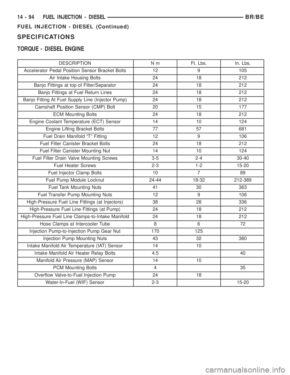
TORQUE - DIESEL ENGINE
DESCRIPTION N m Ft. Lbs. In. Lbs.
Accelerator Pedal Position Sensor Bracket Bolts 12 9 105
Air Intake Housing Bolts 24 18 212
Banjo Fittings at top of Filter/Separator 24 18 212
Banjo Fittings at Fuel Return Lines 24 18 212
Banjo Fitting At Fuel Supply Line (Injector Pump) 24 18 212
Camshaft Position Sensor (CMP) Bolt 20 15 177
ECM Mounting Bolts 24 18 212
Engine Coolant Temperature (ECT) Sensor 14 10 124
Engine Lifting Bracket Bolts 77 57 681
Fuel Drain Manifold ªTº Fitting 12 9 106
Fuel Filter Canister Bracket Bolts 24 18 212
Fuel Filter Canister Mounting Nut 14 10 124
Fuel Filter Drain Valve Mounting Screws 3-5 2-4 30-40
Fuel Heater Screws 2-3 1-2 15-20
Fuel Injector Clamp Bolts 10 7 89
Fuel Pump Module Locknut 24-44 18-32 212-389
Fuel Tank Mounting Nuts 41 30 363
Fuel Transfer Pump Mounting Nuts 12 9 106
High-Pressure Fuel Line Fittings (at Injectors) 38 28 336
High-Pressure Fuel Line Fittings (at Pump) 24 18 212
High-Pressure Fuel Line Clamps-to-Intake Manifold 24 18 212
Hose Clamps at Intercooler Tube 8 6 72
Injection Pump-to-Injection Pump Gear Nut 170 125
Injection Pump Mounting Nuts 43 32 380
Intake Manifold Air Temperature (IAT) Sensor 14 10
Intake Manifold Air Heater Relay Bolts 4.5 40
Manifold Air Pressure (MAP) Sensor 14 10
PCM Mounting Bolts 4 35
Overflow Valve-to-Fuel Injection Pump 24 18
Water-In-Fuel (WIF) Sensor 2-3 15-20
14 - 94 FUEL INJECTION - DIESELBR/BE
FUEL INJECTION - DIESEL (Continued)
Page 1427 of 2255
REMOVAL
(1) Place the front wheels in a straight-ahead posi-
tion.
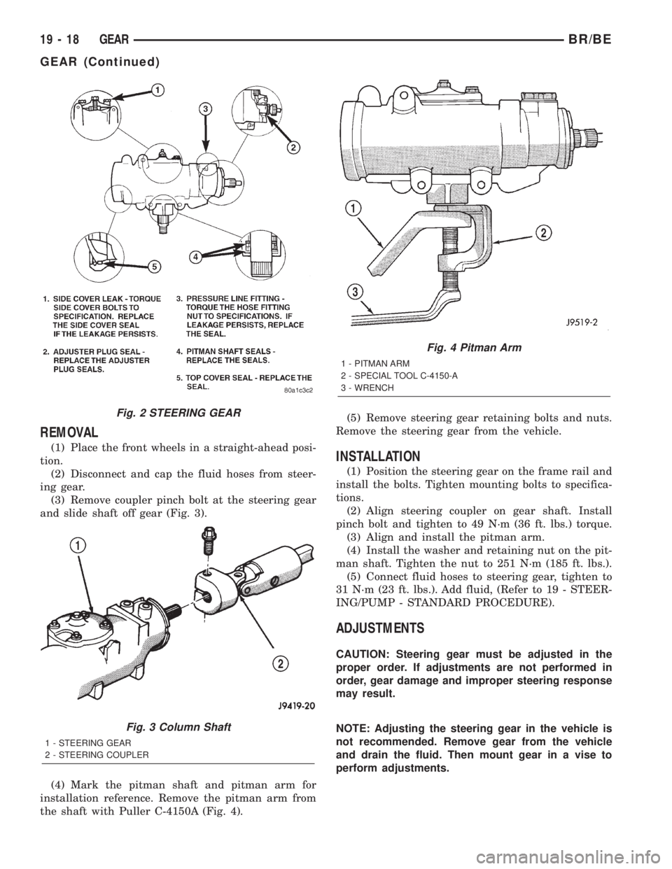
(2) Disconnect and cap the fluid hoses from steer-
ing gear.
(3) Remove coupler pinch bolt at the steering gear
and slide shaft off gear (Fig. 3).
(4) Mark the pitman shaft and pitman arm for
installation reference. Remove the pitman arm from
the shaft with Puller C-4150A (Fig. 4).(5) Remove steering gear retaining bolts and nuts.
Remove the steering gear from the vehicle.INSTALLATION
(1) Position the steering gear on the frame rail and
install the bolts. Tighten mounting bolts to specifica-
tions.
(2) Align steering coupler on gear shaft. Install
pinch bolt and tighten to 49 N´m (36 ft. lbs.) torque.
(3) Align and install the pitman arm.
(4) Install the washer and retaining nut on the pit-
man shaft. Tighten the nut to 251 N´m (185 ft. lbs.).
(5) Connect fluid hoses to steering gear, tighten to
31 N´m (23 ft. lbs.). Add fluid, (Refer to 19 - STEER-
ING/PUMP - STANDARD PROCEDURE).
ADJUSTMENTS
CAUTION: Steering gear must be adjusted in the
proper order. If adjustments are not performed in
order, gear damage and improper steering response
may result.
NOTE: Adjusting the steering gear in the vehicle is
not recommended. Remove gear from the vehicle
and drain the fluid. Then mount gear in a vise to
perform adjustments.
Fig. 2 STEERING GEAR
Fig. 3 Column Shaft
1 - STEERING GEAR
2 - STEERING COUPLER
Fig. 4 Pitman Arm
1 - PITMAN ARM
2 - SPECIAL TOOL C-4150-A
3 - WRENCH
19 - 18 GEARBR/BE
GEAR (Continued)
Page 1444 of 2255
(3) Plug the return line port/ports at the pump.
(4) Position the return line/lines into a large con-
tainer to catch the fluid.
(5) While an assistant is filling the pump reservoir
start the engine.
(6) With the engine running at idle turn the wheel
back and forth.
NOTE: Do not contact or hold the wheel against the
steering stops.
(7) Run a quart of fluid through the system then
stop the engine and install the return line/lines.
(8) Fill the system with fluid and perform Steering
Pump Initial Operation, (Refer to 19 - STEERING/
PUMP - STANDARD PROCEDURE).
(9) Start the engine and run it for fifteen minutes
then stop the engine.
(10) Remove the return line/lines from the pump
and plug the pump port/ports.
(11) Pour fresh fluid into the reservoir and check
the draining fluid for contamination. If the fluid is
still contaminated, disassemble and clean the steer-
ing gear and flush the system again.
(12) Install the return line/lines and perform
Steering Pump Initial Operation, (Refer to 19 -
STEERING/PUMP - STANDARD PROCEDURE).
REMOVAL
REMOVAL - GASOLINE ENGINE
(1) Remove the serpentine drive belt, (Refer to 7 -
COOLING/ACCESSORY DRIVE/DRIVE BELTS -
REMOVAL) OR (Refer to 7 - COOLING/ACCESSORY
DRIVE/DRIVE BELTS - REMOVAL).
(2) Remove the hoses from the power steering
pump and cap the fittings.
(3) Remove battery ground cable and unthread
stud from cylinder head, do not remove from bracket.
(4) Loosen upper bracket bolt and remove the
lower bracket to engine block bolts.
(5) Pivot the pump assembly past the coolant tube.
(6) Remove the upper stud and remove upper bolt
from cylinder head.
(7) Remove steering pump and mounting bracket
from engine as an assembly.
(8) Remove the pump pulley with Puller C-4333, to
access pump attaching bolts, (Refer to 19 - STEER-
ING/PUMP/PULLEY - REMOVAL).
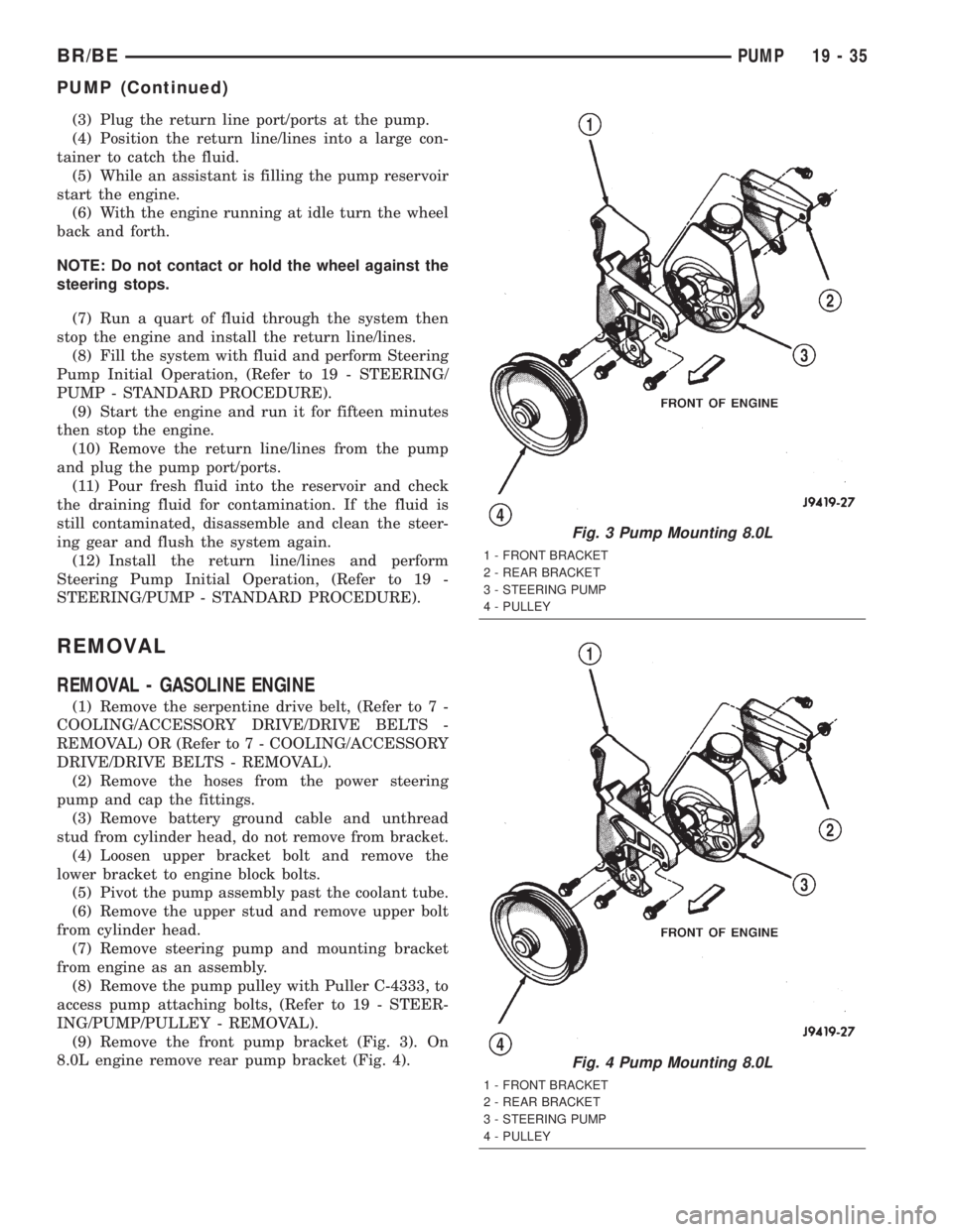
(9) Remove the front pump bracket (Fig. 3). On
8.0L engine remove rear pump bracket (Fig. 4).
Fig. 3 Pump Mounting 8.0L
1 - FRONT BRACKET
2 - REAR BRACKET
3 - STEERING PUMP
4 - PULLEY
Fig. 4 Pump Mounting 8.0L
1 - FRONT BRACKET
2 - REAR BRACKET
3 - STEERING PUMP
4 - PULLEY
BR/BEPUMP 19 - 35
PUMP (Continued)