2002 DODGE RAM parts list
[x] Cancel search: parts listPage 4 of 2255
VEHICLE EMISSION CONTROL
INFORMATION (VECI)
DESCRIPTION
Vehicles equipped with 5.9L V-8 LDC-gas powered
engines have a vehicle emission control information
(VECI) label.
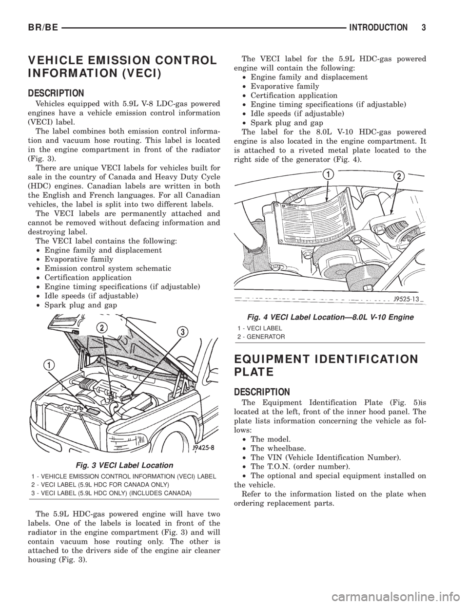
The label combines both emission control informa-
tion and vacuum hose routing. This label is located
in the engine compartment in front of the radiator
(Fig. 3).
There are unique VECI labels for vehicles built for
sale in the country of Canada and Heavy Duty Cycle
(HDC) engines. Canadian labels are written in both
the English and French languages. For all Canadian
vehicles, the label is split into two different labels.
The VECI labels are permanently attached and
cannot be removed without defacing information and
destroying label.
The VECI label contains the following:
²Engine family and displacement
²Evaporative family
²Emission control system schematic
²Certification application
²Engine timing specifications (if adjustable)
²Idle speeds (if adjustable)
²Spark plug and gap
The 5.9L HDC-gas powered engine will have two
labels. One of the labels is located in front of the
radiator in the engine compartment (Fig. 3) and will
contain vacuum hose routing only. The other is
attached to the drivers side of the engine air cleaner
housing (Fig. 3).The VECI label for the 5.9L HDC-gas powered
engine will contain the following:
²Engine family and displacement
²Evaporative family
²Certification application
²Engine timing specifications (if adjustable)
²Idle speeds (if adjustable)
²Spark plug and gap
The label for the 8.0L V-10 HDC-gas powered
engine is also located in the engine compartment. It
is attached to a riveted metal plate located to the
right side of the generator (Fig. 4).
EQUIPMENT IDENTIFICATION
PLATE
DESCRIPTION
The Equipment Identification Plate (Fig. 5)is
located at the left, front of the inner hood panel. The
plate lists information concerning the vehicle as fol-
lows:
²The model.
²The wheelbase.
²The VIN (Vehicle Identification Number).
²The T.O.N. (order number).
²The optional and special equipment installed on
the vehicle.
Refer to the information listed on the plate when
ordering replacement parts.
Fig. 3 VECI Label Location
1 - VEHICLE EMISSION CONTROL INFORMATION (VECI) LABEL
2 - VECI LABEL (5.9L HDC FOR CANADA ONLY)
3 - VECI LABEL (5.9L HDC ONLY) (INCLUDES CANADA)
Fig. 4 VECI Label LocationÐ8.0L V-10 Engine
1 - VECI LABEL
2 - GENERATOR
BR/BEINTRODUCTION 3
Page 154 of 2255
(13) Install the fill hole plug and tighten to 34 N´m
(25 ft. lbs.).
(14) Remove support and lower vehicle.
DIFFERENTIAL - POWR-LOK
DIAGNOSIS AND TESTING - POWR-LOKT
WARNING: WHEN SERVICING VEHICLES WITH A
POWR-LOKTDIFFERENTIAL DO NOT USE THE
ENGINE TO TURN THE AXLE AND WHEELS. BOTH
REAR WHEELS MUST BE RAISED AND THE VEHI-
CLE SUPPORTED. THE AXLE CAN EXERT ENOUGH
FORCE IF ONE WHEEL IS IN CONTACT WITH A
SURFACE TO CAUSE THE VEHICLE TO MOVE.
The differential can be tested without removing the
differential case by measuring rotating torque. Make
sure brakes are not dragging during this measure-
ment.
(1) Place blocks in front and rear of both front
wheels.
(2) Raise one rear wheel until it is completely off
the ground.
(3) Engine off, transmission in neutral, and park-
ing brake off.
(4) Remove wheel and bolt Special Tool 6790 or
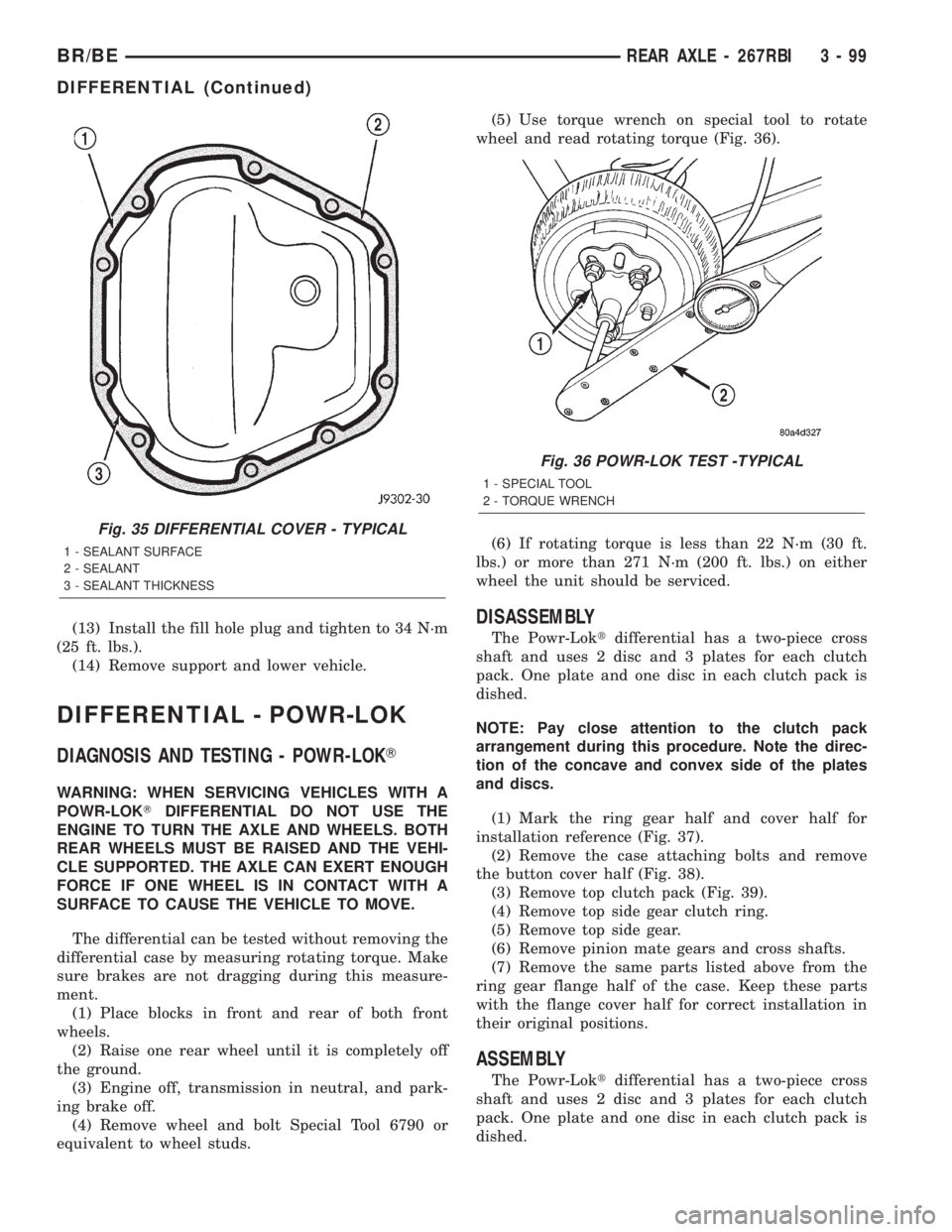
equivalent to wheel studs.(5) Use torque wrench on special tool to rotate
wheel and read rotating torque (Fig. 36).
(6) If rotating torque is less than 22 N´m (30 ft.
lbs.) or more than 271 N´m (200 ft. lbs.) on either
wheel the unit should be serviced.
DISASSEMBLY
The Powr-Loktdifferential has a two-piece cross
shaft and uses 2 disc and 3 plates for each clutch
pack. One plate and one disc in each clutch pack is
dished.
NOTE: Pay close attention to the clutch pack
arrangement during this procedure. Note the direc-
tion of the concave and convex side of the plates
and discs.
(1) Mark the ring gear half and cover half for
installation reference (Fig. 37).
(2) Remove the case attaching bolts and remove
the button cover half (Fig. 38).
(3) Remove top clutch pack (Fig. 39).
(4) Remove top side gear clutch ring.
(5) Remove top side gear.
(6) Remove pinion mate gears and cross shafts.
(7) Remove the same parts listed above from the
ring gear flange half of the case. Keep these parts
with the flange cover half for correct installation in
their original positions.
ASSEMBLY
The Powr-Loktdifferential has a two-piece cross
shaft and uses 2 disc and 3 plates for each clutch
pack. One plate and one disc in each clutch pack is
dished.
Fig. 35 DIFFERENTIAL COVER - TYPICAL
1 - SEALANT SURFACE
2 - SEALANT
3 - SEALANT THICKNESS
Fig. 36 POWR-LOK TEST -TYPICAL
1 - SPECIAL TOOL
2 - TORQUE WRENCH
BR/BEREAR AXLE - 267RBI 3 - 99
DIFFERENTIAL (Continued)
Page 183 of 2255
(12) Fill the differential with Mopar Hypoid Gear
Lubricant or equivalent to bottom of the fill plug
hole.
(13) Install fill hole plug and tighten to 34 N´m (25
ft. lbs.).
(14) Remove support and lower vehicle.
DIFFERENTIAL - TRAC-LOK
DIAGNOSIS AND TESTING - TRAC-LOKT
The most common problem is a chatter noise when
turning corners. Before removing a Trac-lokŸ unit
for repair, drain, flush and refill the axle with the
specified lubricant. A container of Mopar Trac-lokŸ
Lubricant (friction modifier) should be added after
repair service or during a lubricant change.
After changing the lubricant, drive the vehicle and
make 10 to 12 slow, figure-eight turns. This maneu-
ver will pump lubricant through the clutches. This
will correct the condition in most instances. If the
chatter persists, clutch damage could have occurred.
DIFFERENTIAL TEST
The differential can be tested without removing the
differential case by measuring rotating torque. Make
sure brakes are not dragging during this measure-
ment.
(1) Place blocks in front and rear of both front
wheels.
(2) Raise one rear wheel until it is completely off
the ground.
(3) Engine off, transmission in neutral, and park-
ing brake off.
(4) Remove wheel and bolt Special Tool 6790 or
equivalent tool to studs.
(5) Use torque wrench on special tool to rotate
wheel and read rotating torque.
(6) If rotating torque is less than 22 N´m (30 ft.
lbs.) or more than 271 N´m (200 ft. lbs.) on either
wheel the unit should be serviced.
DISASSEMBLY
The Trac-Loktdifferential on this axle has a one-
piece cross shaft and uses one dished disc, regular 5
disc and 7 plates.
NOTE: Pay attention to the clutch pack arrangement
during disassembly. Note the direction of the con-
cave and convex side of the plates and discs.
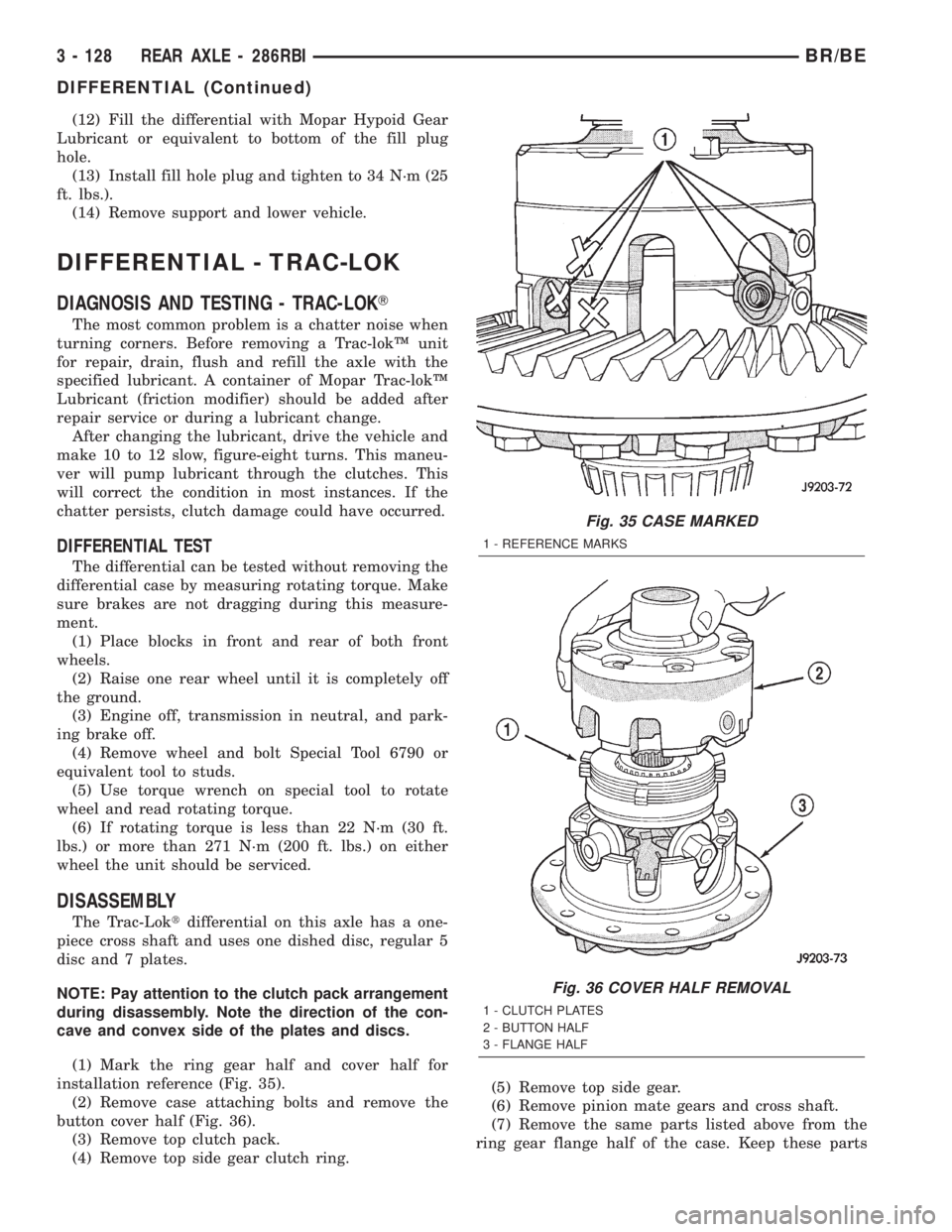
(1) Mark the ring gear half and cover half for
installation reference (Fig. 35).
(2) Remove case attaching bolts and remove the
button cover half (Fig. 36).
(3) Remove top clutch pack.
(4) Remove top side gear clutch ring.(5) Remove top side gear.
(6) Remove pinion mate gears and cross shaft.
(7) Remove the same parts listed above from the
ring gear flange half of the case. Keep these parts
Fig. 35 CASE MARKED
1 - REFERENCE MARKS
Fig. 36 COVER HALF REMOVAL
1 - CLUTCH PLATES
2 - BUTTON HALF
3 - FLANGE HALF
3 - 128 REAR AXLE - 286RBIBR/BE
DIFFERENTIAL (Continued)
Page 602 of 2255
(9) If the vehicle is equipped with an automatic
transmission, install and tighten the two screws that
secure the ACM trim cover to the ACM mounting
bracket. Tighten the screws to 2.2 N´m (20 in. lbs.).
(10) If the vehicle is equipped with a manual
transmission, reinstall the center floor console onto
the floor panel transmission tunnel. (Refer to 23 -
BODY/INTERIOR/CENTER CONSOLE - INSTALLA-
TION).
(11) Do not reconnect the battery negative cable at
this time. The airbag system verification test proce-
dure should be performed following service of any
airbag system component. (Refer to 8 - ELECTRI-
CAL/RESTRAINTS - STANDARD PROCEDURE -
VERIFICATION TEST).
CHILD TETHER
REMOVAL
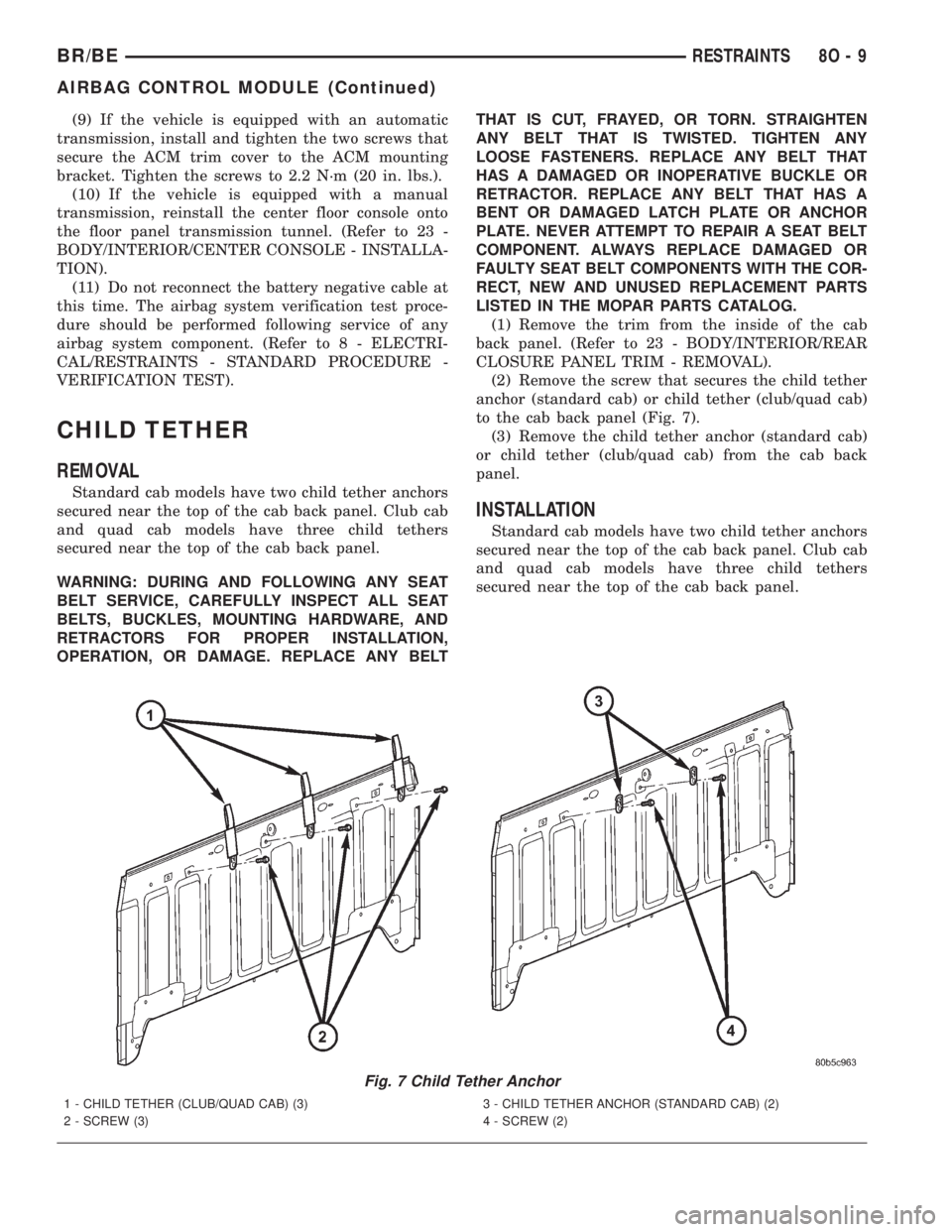
Standard cab models have two child tether anchors
secured near the top of the cab back panel. Club cab
and quad cab models have three child tethers
secured near the top of the cab back panel.
WARNING: DURING AND FOLLOWING ANY SEAT
BELT SERVICE, CAREFULLY INSPECT ALL SEAT
BELTS, BUCKLES, MOUNTING HARDWARE, AND
RETRACTORS FOR PROPER INSTALLATION,
OPERATION, OR DAMAGE. REPLACE ANY BELTTHAT IS CUT, FRAYED, OR TORN. STRAIGHTEN
ANY BELT THAT IS TWISTED. TIGHTEN ANY
LOOSE FASTENERS. REPLACE ANY BELT THAT
HAS A DAMAGED OR INOPERATIVE BUCKLE OR
RETRACTOR. REPLACE ANY BELT THAT HAS A
BENT OR DAMAGED LATCH PLATE OR ANCHOR
PLATE. NEVER ATTEMPT TO REPAIR A SEAT BELT
COMPONENT. ALWAYS REPLACE DAMAGED OR
FAULTY SEAT BELT COMPONENTS WITH THE COR-
RECT, NEW AND UNUSED REPLACEMENT PARTS
LISTED IN THE MOPAR PARTS CATALOG.
(1) Remove the trim from the inside of the cab
back panel. (Refer to 23 - BODY/INTERIOR/REAR
CLOSURE PANEL TRIM - REMOVAL).
(2) Remove the screw that secures the child tether
anchor (standard cab) or child tether (club/quad cab)
to the cab back panel (Fig. 7).
(3) Remove the child tether anchor (standard cab)
or child tether (club/quad cab) from the cab back
panel.
INSTALLATION
Standard cab models have two child tether anchors
secured near the top of the cab back panel. Club cab
and quad cab models have three child tethers
secured near the top of the cab back panel.
Fig. 7 Child Tether Anchor
1 - CHILD TETHER (CLUB/QUAD CAB) (3)
2 - SCREW (3)3 - CHILD TETHER ANCHOR (STANDARD CAB) (2)
4 - SCREW (2)
BR/BERESTRAINTS 8O - 9
AIRBAG CONTROL MODULE (Continued)
Page 603 of 2255
WARNING: DURING AND FOLLOWING ANY SEAT
BELT SERVICE, CAREFULLY INSPECT ALL SEAT
BELTS, BUCKLES, MOUNTING HARDWARE, AND
RETRACTORS FOR PROPER INSTALLATION,
OPERATION, OR DAMAGE. REPLACE ANY BELT
THAT IS CUT, FRAYED, OR TORN. STRAIGHTEN
ANY BELT THAT IS TWISTED. TIGHTEN ANY
LOOSE FASTENERS. REPLACE ANY BELT THAT
HAS A DAMAGED OR INOPERATIVE BUCKLE OR
RETRACTOR. REPLACE ANY BELT THAT HAS A
BENT OR DAMAGED LATCH PLATE OR ANCHOR
PLATE. NEVER ATTEMPT TO REPAIR A SEAT BELT
COMPONENT. ALWAYS REPLACE DAMAGED OR
FAULTY SEAT BELT COMPONENTS WITH THE COR-
RECT, NEW AND UNUSED REPLACEMENT PARTS
LISTED IN THE MOPAR PARTS CATALOG.
(1) Position the child tether anchor (standard cab)
or child tether (club/quad cab) onto the cab back
panel (Fig. 7).
(2) Install and tighten the screw that secures the
child tether anchor (standard cab) or child tether
(club/quad cab) onto the cab back panel. Tighten the
screw to 13.5 N´m (120 in. lbs.).
(3) Reinstall the trim onto the inside of the cab
back panel. (Refer to 23 - BODY/INTERIOR/REAR
CLOSURE PANEL TRIM - INSTALLATION).
CLOCKSPRING
DESCRIPTION
The clockspring assembly is secured with two inte-
gral plastic latches onto the steering column lock
housing near the top of the steering column, behind
the steering wheel. The clockspring consists of a flat,
round molded plastic case with a stubby tail that
hangs below the steering column and contains a con-
nector receptacle and a long pigtail wire with connec-
tor that face toward the instrument panel. Within
the plastic housing is a spool-like molded plastic
rotor with a large exposed hub. The upper surface of
the rotor hub has a large center hole, two large flats,
two auto-locking tabs, and three short pigtail wires
with connectors that face toward the steering wheel.
The lower surface of the rotor hub has two integral
turn signal cancelling cam lobes. Within the plastic
case and wound around the rotor spool is a long rib-
bon-like tape that consists of several thin copper wire
leads sandwiched between two thin plastic mem-
branes. The outer end of the tape terminates at the
connector receptacle and pigtail wire that face the
instrument panel, while the inner end of the tape
terminates at the pigtail wires on the hub of the
clockspring rotor that face the steering wheel.
Service replacement clocksprings are shipped pre-
centered and with a piece of tape covering theengaged auto-locking tabs. The auto-locking tabs
secure the centered clockspring rotor to the clock-
spring case during shipment, but these tabs are auto-
matically disengaged once the clockspring is installed
on the steering column. (Refer to 8 - ELECTRICAL/
RESTRAINTS/CLOCKSPRING - STANDARD PRO-
CEDURE - CLOCKSPRING CENTERING).
The clockspring cannot be repaired. If the clock-
spring is faulty, damaged, or if the driver airbag has
been deployed, the clockspring must be replaced.
OPERATION
The clockspring is a mechanical electrical circuit
component that is used to provide continuous electri-
cal continuity between the fixed instrument panel
wire harness and the electrical components mounted
on or in the rotating steering wheel. On this model
the rotating electrical components include the driver
airbag, the horn switch, the speed control switches,
and the remote radio switches if the vehicle is so
equipped. The clockspring case is positioned and
secured to the upper steering column lock housing by
two integral plastic latches. The connector receptacle
on the tail of the fixed clockspring housing connect
the clockspring to the vehicle electrical system
through a take out with connector from the instru-
ment panel wire harness. The lower clockspring pig-
tail on the tail of the clockspring housing connect the
clockspring driver airbag circuits to a separate take
out and connector of the instrument panel wire har-
ness located near the lower instrument panel rein-
forcement, below the steering column. The
clockspring rotor is movable and is keyed to the hub
of the steering wheel by two large flats that are
molded into the rotor hub. The two lobes on the
lower surface of the clockspring rotor hub contact a
turn signal cancel actuator of the multi-function
switch to provide automatic turn signal cancellation.
The pigtail wires on the upper surface of the clock-
spring connect the clockspring to the horn switch, the
two speed control switches, and the remote radio
switches on vehicles that are so equipped.
Like the clockspring in a timepiece, the clockspring
tape has travel limits and can be damaged by being
wound too tightly during full stop-to-stop steering
wheel rotation. To prevent this from occurring, the
clockspring must be centered when it is installed on
the steering column. Centering the clockspring
indexes the clockspring spool to the movable steering
components so that the tape can operate within its
designed travel limits. However, if the clockspring is
removed from the steering column or if the steering
shaft is disconnected from the steering gear, the
clockspring spool can change position relative to the
movable steering components and must be re-cen-
tered following completion of the service or the tape
8O - 10 RESTRAINTSBR/BE
CHILD TETHER (Continued)
Page 611 of 2255

ELECTRICAL/RESTRAINTS/CLOCKSPRING -
REMOVAL) and (Refer to 19 - STEERING/COLUMN
- REMOVAL).
WARNING: DISABLE THE AIRBAG SYSTEM
BEFORE ATTEMPTING ANY STEERING WHEEL,
STEERING COLUMN, OR INSTRUMENT PANEL
COMPONENT DIAGNOSIS OR SERVICE. DISCON-
NECT AND ISOLATE THE BATTERY NEGATIVE
(GROUND) CABLE, THEN WAIT TWO MINUTES FOR
THE AIRBAG SYSTEM CAPACITOR TO DISCHARGE
BEFORE PERFORMING FURTHER DIAGNOSIS OR
SERVICE. THIS IS THE ONLY SURE WAY TO DIS-
ABLE THE AIRBAG SYSTEM. FAILURE TO TAKE
THE PROPER PRECAUTIONS COULD RESULT IN
ACCIDENTAL AIRBAG DEPLOYMENT AND POSSI-
BLE PERSONAL INJURY.
WARNING: USE EXTREME CARE TO PREVENT ANY
FOREIGN MATERIAL FROM ENTERING THE DRIVER
AIRBAG, OR BECOMING ENTRAPPED BETWEEN
THE DRIVER AIRBAG CUSHION AND THE DRIVER
AIRBAG TRIM COVER. FAILURE TO OBSERVE THIS
WARNING COULD RESULT IN OCCUPANT INJURIES
UPON AIRBAG DEPLOYMENT.
WARNING: THE DRIVER AIRBAG TRIM COVER
MUST NEVER BE PAINTED. REPLACEMENT TRIM
COVERS ARE SERVICED IN THE ORIGINAL COL-
ORS. PAINT MAY CHANGE THE WAY IN WHICH THE
MATERIAL OF THE TRIM COVER RESPONDS TO AN
AIRBAG DEPLOYMENT. FAILURE TO OBSERVE
THIS WARNING COULD RESULT IN OCCUPANT
INJURIES UPON AIRBAG DEPLOYMENT.
(1) Assemble the driver airbag trim cover onto the
airbag housing. (Refer to 8 - ELECTRICAL/RE-
STRAINTS/DRIVER AIRBAG - ASSEMBLY).
(2) When installing the driver airbag, reconnect
the clockspring driver airbag pigtail wire harness
connector to the airbag inflator connector receptacle
by pressing straight in on the connector (Fig. 10). You
can be certain that the connector is fully engaged by
listening carefully for a distinct, audible click as the
connector snaps into place.
(3) Reconnect the clockspring horn switch pigtail
wire harness connector to the horn switch feed pig-
tail wire connector, which is located on the back of
the driver airbag.
(4) Carefully position the driver airbag in the
steering wheel. Be certain that the clockspring pig-
tail wires in the steering wheel hub area are not
pinched between the driver airbag and the steering
wheel.(5) From the underside of the steering wheel,
install and tighten the two screws that secure the
driver airbag to the steering wheel armature.
Tighten the screws to 10.2 N´m (90 in. lbs.).
(6) Do not reconnect the battery negative cable at
this time. The airbag system verification test proce-
dure should be performed following service of any
airbag system component. (Refer to 8 - ELECTRI-
CAL/RESTRAINTS - STANDARD PROCEDURE -
VERIFICATION TEST).
FRONT SEAT BELT &
RETRACTOR
REMOVAL
REMOVAL - STANDARD CAB
WARNING: DURING AND FOLLOWING ANY SEAT
BELT SERVICE, CAREFULLY INSPECT ALL SEAT
BELTS, BUCKLES, MOUNTING HARDWARE, AND
RETRACTORS FOR PROPER INSTALLATION,
OPERATION, OR DAMAGE. REPLACE ANY BELT
THAT IS CUT, FRAYED, OR TORN. STRAIGHTEN
ANY BELT THAT IS TWISTED. TIGHTEN ANY
LOOSE FASTENERS. REPLACE ANY BELT THAT
HAS A DAMAGED OR INOPERATIVE BUCKLE OR
RETRACTOR. REPLACE ANY BELT THAT HAS A
BENT OR DAMAGED LATCH PLATE OR ANCHOR
PLATE. NEVER ATTEMPT TO REPAIR A SEAT BELT
COMPONENT. ALWAYS REPLACE DAMAGED OR
FAULTY SEAT BELT COMPONENTS WITH THE COR-
RECT, NEW AND UNUSED REPLACEMENT PARTS
LISTED IN THE MOPAR PARTS CATALOG.
(1) Move the front seats to their most forward
position for easiest access to the front shoulder belt
lower seat belt anchor plate, the retractor, and the
B-pillar.
(2) Remove the screw that secures the lower seat
belt anchor plate to the floor panel near the base of
the B-pillar.
(3) Unsnap and lift the front shoulder belt turning
loop cover to access the screw that secures the turn-
ing loop to the height adjuster (Fig. 15).
(4) Remove the screw that secures the shoulder
belt turning loop to the height adjuster.
(5) Remove the shoulder belt turning loop from the
height adjuster.
(6) Remove the trim from the B-pillar. (Refer to 23
- BODY/INTERIOR/B-PILLAR TRIM - REMOVAL).
(7) Disengage the front seat shoulder belt turning
loop and lower seat belt anchor plate from the B-pil-
lar trim.
8O - 18 RESTRAINTSBR/BE
DRIVER AIRBAG (Continued)
Page 612 of 2255

(8) Remove the screw that secures the retractor to
the B-pillar.
(9) Remove the front shoulder belt and retractor
from the B-pillar.
REMOVAL - CLUB/QUAD CAB
The front seat shoulder belt and retractor are inte-
gral to the driver and passenger front seat backs on
club cab and quad cab models.
WARNING: DURING AND FOLLOWING ANY SEAT
BELT SERVICE, CAREFULLY INSPECT ALL SEAT
BELTS, BUCKLES, MOUNTING HARDWARE, AND
RETRACTORS FOR PROPER INSTALLATION,
OPERATION, OR DAMAGE. REPLACE ANY BELT
THAT IS CUT, FRAYED, OR TORN. STRAIGHTEN
ANY BELT THAT IS TWISTED. TIGHTEN ANY
LOOSE FASTENERS. REPLACE ANY BELT THAT
HAS A DAMAGED OR INOPERATIVE BUCKLE OR
RETRACTOR. REPLACE ANY BELT THAT HAS A
BENT OR DAMAGED LATCH PLATE OR ANCHOR
PLATE. NEVER ATTEMPT TO REPAIR A SEAT BELT
COMPONENT. ALWAYS REPLACE DAMAGED OR
FAULTY SEAT BELT COMPONENTS WITH THE COR-
RECT, NEW AND UNUSED REPLACEMENT PARTS
LISTED IN THE MOPAR PARTS CATALOG.
(1) Remove the trim cover from the front seat back
frame. (Refer to 23 - BODY/SEATS/SEAT BACK
COVER - REMOVAL).
(2) Remove the screws that secure the retractor
cover to the seat back frame.
(3) Remove the retractor cover from the seat back
frame.
(4) Remove the two screws that secure the seat
belt retractor to the seat back frame (Fig. 16).(5) Remove the front shoulder belt and retractor
from the seat back frame.
INSTALLATION
INSTALLATION - STANDARD CAB
WARNING: DURING AND FOLLOWING ANY SEAT
BELT SERVICE, CAREFULLY INSPECT ALL SEAT
BELTS, BUCKLES, MOUNTING HARDWARE, AND
RETRACTORS FOR PROPER INSTALLATION,
OPERATION, OR DAMAGE. REPLACE ANY BELT
THAT IS CUT, FRAYED, OR TORN. STRAIGHTEN
ANY BELT THAT IS TWISTED. TIGHTEN ANY
LOOSE FASTENERS. REPLACE ANY BELT THAT
HAS A DAMAGED OR INOPERATIVE BUCKLE OR
RETRACTOR. REPLACE ANY BELT THAT HAS A
BENT OR DAMAGED LATCH PLATE OR ANCHOR
PLATE. NEVER ATTEMPT TO REPAIR A SEAT BELT
COMPONENT. ALWAYS REPLACE DAMAGED OR
FAULTY SEAT BELT COMPONENTS WITH THE COR-
RECT, NEW AND UNUSED REPLACEMENT PARTS
LISTED IN THE MOPAR PARTS CATALOG.
(1) Position the retractor onto the B-pillar (Fig.
15).
(2) Install and tighten the screw that secures the
retractor to the B-pillar. Tighten the screw to 40 N´m
(29 ft. lbs.).
(3) Engage the front seat shoulder belt turning
loop and lower seat belt anchor plate with the B-pil-
lar trim.
(4) Reinstall the trim onto the B-pillar. (Refer to
23 - BODY/INTERIOR/B-PILLAR TRIM - INSTAL-
LATION).
(5) Position the shoulder belt turning loop onto the
height adjuster.
Fig. 15 Front Shoulder Belt - Standard Cab
1 - TURNING LOOP COVER
2 - SHOULDER BELT ASSEMBLY
Fig. 16 Seat Belt Retractor
1 - RETRACTOR SCREWS
2 - SEAT BACK FRAME
BR/BERESTRAINTS 8O - 19
FRONT SEAT BELT & RETRACTOR (Continued)
Page 613 of 2255
(6) Install and tighten the screw that secures the
shoulder belt turning loop to the height adjuster.
Tighten the screw to 30 N´m (22 ft. lbs.).
(7) Fold and snap the cover over the front shoulder
belt turning loop to conceal the screw that secures
the turning loop to the height adjuster.
(8) Install and tighten the screw that secures the
lower seat belt anchor plate to the floor panel near
the base of the B-pillar. Tighten the screw to 40 N´m
(29 ft. lbs.).
INSTALLATION - CLUB/QUAD CAB
The front seat shoulder belt and retractor are inte-
gral to the driver and passenger front seat backs on
club cab and quad cab models.
WARNING: DURING AND FOLLOWING ANY SEAT
BELT SERVICE, CAREFULLY INSPECT ALL SEAT
BELTS, BUCKLES, MOUNTING HARDWARE, AND
RETRACTORS FOR PROPER INSTALLATION,
OPERATION, OR DAMAGE. REPLACE ANY BELT
THAT IS CUT, FRAYED, OR TORN. STRAIGHTEN
ANY BELT THAT IS TWISTED. TIGHTEN ANY
LOOSE FASTENERS. REPLACE ANY BELT THAT
HAS A DAMAGED OR INOPERATIVE BUCKLE OR
RETRACTOR. REPLACE ANY BELT THAT HAS A
BENT OR DAMAGED LATCH PLATE OR ANCHOR
PLATE. NEVER ATTEMPT TO REPAIR A SEAT BELT
COMPONENT. ALWAYS REPLACE DAMAGED OR
FAULTY SEAT BELT COMPONENTS WITH THE COR-
RECT, NEW AND UNUSED REPLACEMENT PARTS
LISTED IN THE MOPAR PARTS CATALOG.
(1) Position the front shoulder belt and retractor
onto the seat back frame.
(2) Install and tighten the two screws that secure
the seat belt retractor to the seat back frame (Fig.
16). Tighten the screws to 16 N´m (12 ft. lbs.).
(3) Position the retractor cover onto the seat back
frame.
(4) Install and tighten the screws that secure the
retractor cover to the seat back frame. Tighten the
screws to 2 N´m (17 in. lbs.).
(5) Reinstall the trim cover onto the front seat
back frame. (Refer to 23 - BODY/SEATS/SEAT BACK
COVER - INSTALLATION).
FRONT SEAT BELT BUCKLE
REMOVAL
WARNING: DURING AND FOLLOWING ANY SEAT
BELT SERVICE, CAREFULLY INSPECT ALL SEAT
BELTS, BUCKLES, MOUNTING HARDWARE, AND
RETRACTORS FOR PROPER INSTALLATION,
OPERATION, OR DAMAGE. REPLACE ANY BELTTHAT IS CUT, FRAYED, OR TORN. STRAIGHTEN
ANY BELT THAT IS TWISTED. TIGHTEN ANY
LOOSE FASTENERS. REPLACE ANY BELT THAT
HAS A DAMAGED OR INOPERATIVE BUCKLE OR
RETRACTOR. REPLACE ANY BELT THAT HAS A
BENT OR DAMAGED LATCH PLATE OR ANCHOR
PLATE. NEVER ATTEMPT TO REPAIR A SEAT BELT
COMPONENT. ALWAYS REPLACE DAMAGED OR
FAULTY SEAT BELT COMPONENTS WITH THE COR-
RECT, NEW AND UNUSED REPLACEMENT PARTS
LISTED IN THE MOPAR PARTS CATALOG.
(1) Move the front seat to its most forward position
for easiest access to the front seat belt buckle
anchors.
(2) Tilt both front seat backs forward far enough to
access the seat belt buckle anchor screws.
(3) On the driver's side only, disconnect the body
wire harness connector for the seat belt switch from
the seat belt switch pigtail wire connector on the seat
belt buckle.
(4) Remove the screw that secures the seat belt
buckle to the anchor on the seat cushion frame.
(5) Remove the front seat belt buckle from the seat
cushion frame.
INSTALLATION
WARNING: DURING AND FOLLOWING ANY SEAT
BELT SERVICE, CAREFULLY INSPECT ALL SEAT
BELTS, BUCKLES, MOUNTING HARDWARE, AND
RETRACTORS FOR PROPER INSTALLATION,
OPERATION, OR DAMAGE. REPLACE ANY BELT
THAT IS CUT, FRAYED, OR TORN. STRAIGHTEN
ANY BELT THAT IS TWISTED. TIGHTEN ANY
LOOSE FASTENERS. REPLACE ANY BELT THAT
HAS A DAMAGED OR INOPERATIVE BUCKLE OR
RETRACTOR. REPLACE ANY BELT THAT HAS A
BENT OR DAMAGED LATCH PLATE OR ANCHOR
PLATE. NEVER ATTEMPT TO REPAIR A SEAT BELT
COMPONENT. ALWAYS REPLACE DAMAGED OR
FAULTY SEAT BELT COMPONENTS WITH THE COR-
RECT, NEW AND UNUSED REPLACEMENT PARTS
LISTED IN THE MOPAR PARTS CATALOG.
(1) Position the front seat belt buckle onto the seat
cushion frame.
(2) On the driver's side only, reconnect the body
wire harness connector for the seat belt switch to the
seat belt switch pigtail wire connector on the seat
belt buckle.
(3) Install and tighten the screw that secures the
seat belt buckle to the anchor on the seat cushion
frame. Tighten the screw to 40 N´m (29 ft. lbs.).
8O - 20 RESTRAINTSBR/BE
FRONT SEAT BELT & RETRACTOR (Continued)