2002 DODGE RAM steering torque chart
[x] Cancel search: steering torque chartPage 32 of 2255
FRONT - 2WD
TABLE OF CONTENTS
page page
FRONT - 2WD
DESCRIPTION
DESCRIPTION........................7
DESCRIPTION........................8
SPECIFICATIONS
TORQUE CHART......................8
SPECIAL TOOLS
INDEPENDENT FRONT SUSPENSION......9
HUB / BEARING
REMOVAL.............................9
INSTALLATION..........................9
KNUCKLE
REMOVAL.............................10
INSTALLATION.........................10
LOWER BALL JOINT
DIAGNOSIS AND TESTING - LOWER BALL
JOINT..............................10
LOWER CONTROL ARM
REMOVAL.............................10INSTALLATION.........................10
SHOCK
DIAGNOSIS AND TESTING - SHOCK........11
REMOVAL.............................11
INSTALLATION.........................11
SPRING
REMOVAL.............................11
INSTALLATION.........................12
STABILIZER BAR
REMOVAL.............................12
INSTALLATION.........................12
UPPER BALL JOINT
DIAGNOSIS AND TESTING - UPPER BALL
JOINT..............................12
UPPER CONTROL ARM
REMOVAL.............................13
INSTALLATION.........................13
FRONT - 2WD
DESCRIPTION
DESCRIPTION
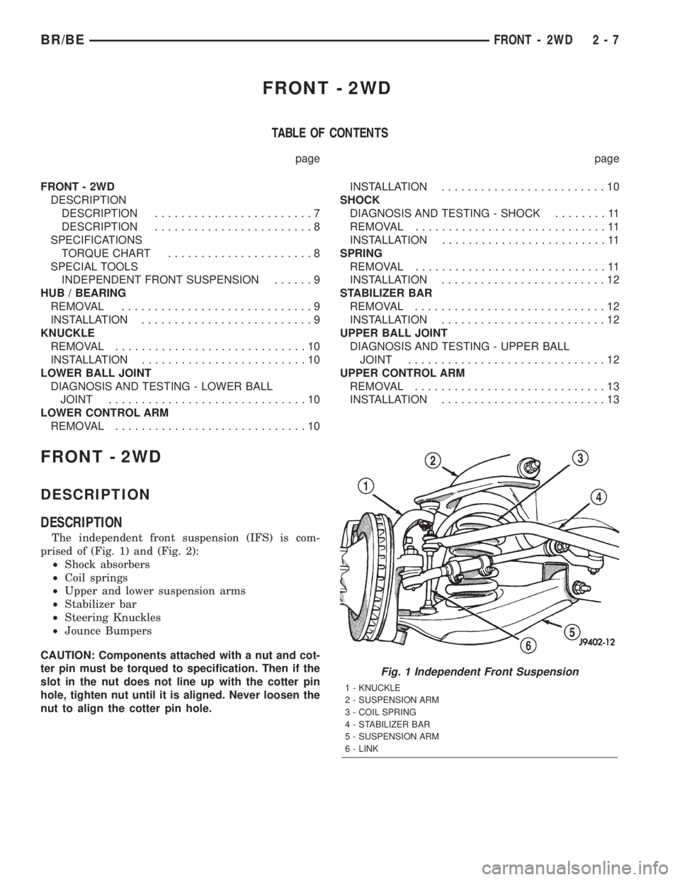
The independent front suspension (IFS) is com-
prised of (Fig. 1) and (Fig. 2):
²Shock absorbers
²Coil springs
²Upper and lower suspension arms
²Stabilizer bar
²Steering Knuckles
²Jounce Bumpers
CAUTION: Components attached with a nut and cot-
ter pin must be torqued to specification. Then if the
slot in the nut does not line up with the cotter pin
hole, tighten nut until it is aligned. Never loosen the
nut to align the cotter pin hole.
Fig. 1 Independent Front Suspension
1 - KNUCKLE
2 - SUSPENSION ARM
3 - COIL SPRING
4 - STABILIZER BAR
5 - SUSPENSION ARM
6 - LINK
BR/BEFRONT - 2WD 2 - 7
Page 39 of 2255
FRONT - 4WD
TABLE OF CONTENTS
page page
FRONT - 4WD
DESCRIPTION
DESCRIPTION........................14
DESCRIPTION........................15
SPECIFICATIONS
TORQUE CHART......................15
SPECIAL TOOLS
LINK/COIL SUSPENSION...............16
HUB / BEARING
REMOVAL.............................16
INSTALLATION.........................17
KNUCKLE
REMOVAL.............................19
INSTALLATION.........................19
UPPER CONTROL ARM
REMOVAL.............................19
INSTALLATION.........................19
UPPER BALL JOINT
REMOVAL - DANA 44 & 60................19
INSTALLATION
INSTALLATION - DANA 44 AXLE..........20
INSTALLATION - DANA 60 AXLE..........20
LOWER CONTROL ARM
REMOVAL.............................20INSTALLATION.........................20
LOWER BALL JOINT
REMOVAL
REMOVAL - DANA 44 AXLE..............21
REMOVAL - DANA 60 AXLE..............21
INSTALLATION
INSTALLATION - DANA 44 AXLE..........21
INSTALLATION - DANA 60 AXLE..........22
SHOCK
DIAGNOSIS AND TESTING - SHOCK........22
REMOVAL.............................22
INSTALLATION.........................22
SPRING
REMOVAL.............................23
INSTALLATION.........................23
STABILIZER BAR
REMOVAL.............................23
INSTALLATION.........................23
TRACK BAR
DIAGNOSIS AND TESTING - TRACK BAR....24
REMOVAL.............................24
INSTALLATION.........................24
FRONT - 4WD
DESCRIPTION
DESCRIPTION
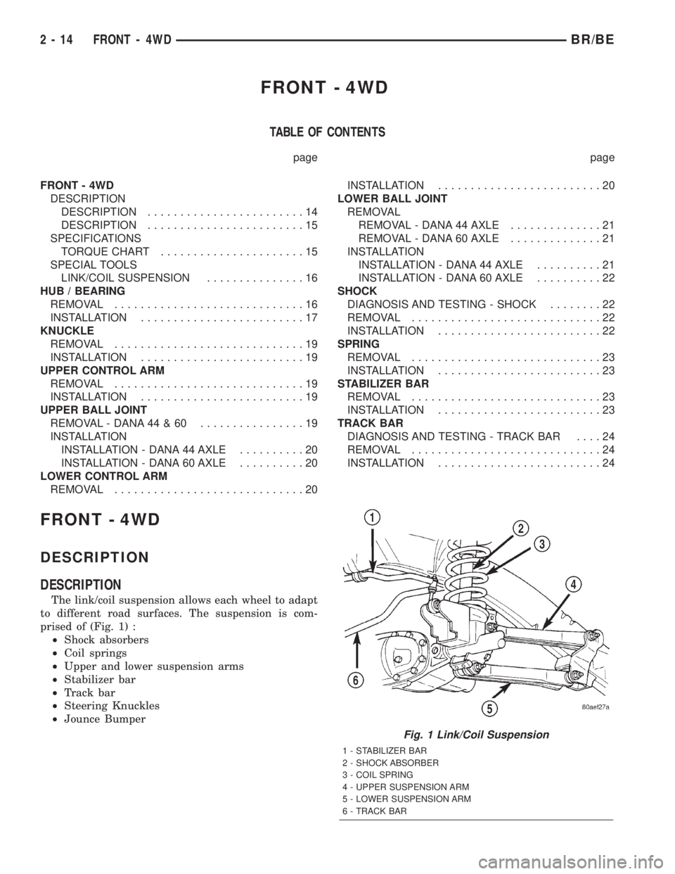
The link/coil suspension allows each wheel to adapt
to different road surfaces. The suspension is com-
prised of (Fig. 1) :
²Shock absorbers
²Coil springs
²Upper and lower suspension arms
²Stabilizer bar
²Track bar
²Steering Knuckles
²Jounce Bumper
Fig. 1 Link/Coil Suspension
1 - STABILIZER BAR
2 - SHOCK ABSORBER
3 - COIL SPRING
4 - UPPER SUSPENSION ARM
5 - LOWER SUSPENSION ARM
6 - TRACK BAR
2 - 14 FRONT - 4WDBR/BE
Page 50 of 2255
REAR
TABLE OF CONTENTS
page page
REAR
DESCRIPTION.........................25
DIAGNOSIS AND TESTING - SPRING AND
SHOCK.............................25
SPECIFICATIONS
TORQUE CHART......................26
SPECIAL TOOLS
SUSPENSION-REAR...................27
BUSHINGS
REMOVAL.............................27INSTALLATION.........................27
SHOCK
REMOVAL.............................27
INSTALLATION.........................27
SPRING
REMOVAL.............................27
INSTALLATION.........................28
STABILIZER BAR
REMOVAL.............................29
INSTALLATION.........................29
REAR
DESCRIPTION
The rear suspension is comprised of:
²Shock Absorbers
²Jounce Bumpers
²Stabilizer Bar (optional)
²Leaf Springs
²Drive Axle
CAUTION: A vehicle should always be loaded so
the vehicle weight center-line is located immedi-
ately forward of the rear axle. Correct vehicle load-
ing provides proper front tire-to-road contact. This
results in maximum vehicle handling stability and
safety. Incorrect vehicle weight distribution can
cause excessive tire tread wear, spring fatigue or
failure, and erratic steering.
CAUTION: Suspension components with rubber/ure-
thane bushings (except stabilizer bar) should be
tightened with the vehicle at normal ride height. It is
important to have the springs supporting the weight
of the vehicle when the fasteners are torqued. If
springs are not at their normal ride position, vehicle
ride comfort could be affected and premature bush-
ing wear may occur.
DIAGNOSIS AND TESTING - SPRING AND
SHOCK
A knocking or rattling noise from a shock absorber
may be caused by movement between mounting
bushings and metal brackets or attaching compo-
nents. These noises can usually be stopped by tight-
ening the attaching nuts. If the noise persists,
inspect for damaged and worn bushings, and attach-
ing components. Repair as necessary if any of these
conditions exist.
A squeaking noise from the shock absorber may be
caused by the hydraulic valving and may be intermit-
tent. This condition is not repairable and the shock
absorber must be replaced.
The shock absorbers are not refillable or adjust-
able. If a malfunction occurs, the shock absorber
must be replaced. To test a shock absorber, hold it in
an upright position and force the piston in and out of
the cylinder four or five times. The action throughout
each stroke should be smooth and even.
The spring eye and shock absorber bushings do not
require any type of lubrication. Do not attempt to
stop spring bushing noise by lubricating them.
Grease and mineral oil-base lubricants will deterio-
rate the bushing rubber.
If the vehicle is used for severe, off-road operation,
the springs should be examined periodically. Check
for broken and shifted leafs, loose and missing clips,
and broken center bolts. Refer to Spring and Shock
Absorber Diagnosis chart for additional information.
BR/BEREAR 2 - 25
Page 224 of 2255
BRAKES - ABS
TABLE OF CONTENTS
page page
BRAKES - ABS
DESCRIPTION.........................35
OPERATION...........................36
DIAGNOSIS AND TESTING - ANTILOCK
BRAKES............................36
STANDARD PROCEDURE
STANDARD PROCEDURE - RWAL SERVICE
PRECAUTIONS.......................36
STANDARD PROCEDURE - BLEEDING ABS
BRAKE SYSTEM......................36
SPECIFICATIONS
TORQUE CHART......................37
FRONT WHEEL SPEED SENSOR
DESCRIPTION.........................38
OPERATION...........................38
REMOVAL
REMOVAL - 4X2......................39REMOVAL - 4X4......................39
INSTALLATION
INSTALLATION - 4X2...................39
INSTALLATION - 4X4...................39
REAR WHEEL SPEED SENSOR
DIAGNOSIS AND TESTING - REAR WHEEL
SPEED SENSOR......................40
REMOVAL.............................40
INSTALLATION.........................40
HCU (HYDRAULIC CONTROL UNIT)
DESCRIPTION.........................40
OPERATION...........................40
REMOVAL.............................41
INSTALLATION.........................41
BRAKES - ABS
DESCRIPTION
The antilock brake system (ABS) is an electroni-
cally operated, all wheel brake control system. 2500
and 3500 vehicles have Electronic Brake Distribution
(EBD) designed into the systen which eliminates the
combination/proportioning valve.
The system is designed to prevent wheel lockup
and maintain steering control during periods of high
wheel slip when braking. Preventing lockup is accom-
plished by modulating fluid pressure to the wheel
brake units.
The hydraulic system is a three channel design.
The front wheel brakes are controlled individually
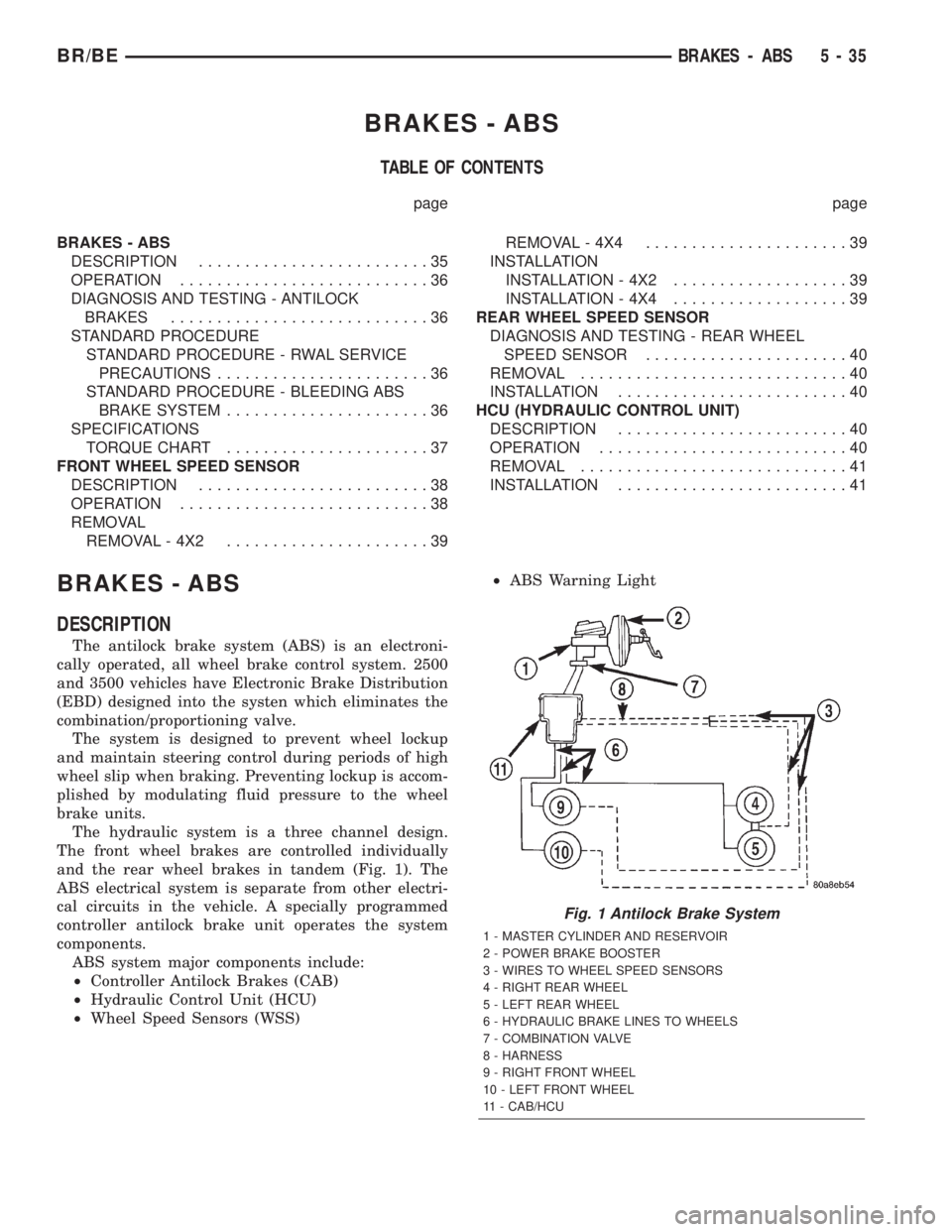
and the rear wheel brakes in tandem (Fig. 1). The
ABS electrical system is separate from other electri-
cal circuits in the vehicle. A specially programmed
controller antilock brake unit operates the system
components.
ABS system major components include:
²Controller Antilock Brakes (CAB)
²Hydraulic Control Unit (HCU)
²Wheel Speed Sensors (WSS)²ABS Warning Light
Fig. 1 Antilock Brake System
1 - MASTER CYLINDER AND RESERVOIR
2 - POWER BRAKE BOOSTER
3 - WIRES TO WHEEL SPEED SENSORS
4 - RIGHT REAR WHEEL
5 - LEFT REAR WHEEL
6 - HYDRAULIC BRAKE LINES TO WHEELS
7 - COMBINATION VALVE
8 - HARNESS
9 - RIGHT FRONT WHEEL
10 - LEFT FRONT WHEEL
11 - CAB/HCU
BR/BEBRAKES - ABS 5 - 35
Page 1415 of 2255
COLUMN
TABLE OF CONTENTS
page page
COLUMN
DESCRIPTION..........................6
OPERATION
SERVICE PRECAUTIONS................6
REMOVAL.............................6
INSTALLATION..........................8
SPECIFICATIONS
TORQUE CHART......................9
KEY-IN IGNITION SWITCH
DESCRIPTION..........................9
DIAGNOSIS AND TESTING - IGNITION
SWITCH AND KEY LOCK CYLINDER.......9
LOCK CYLINDER
REMOVAL.............................10INSTALLATION.........................10
IGNITION SWITCH
DESCRIPTION.........................11
OPERATION...........................11
DIAGNOSIS AND TESTING - IGNITION
SWITCH.............................11
REMOVAL.............................12
INSTALLATION.........................12
GEAR SHIFT LEVER
REMOVAL.............................14
INSTALLATION.........................15
STEERING WHEEL
REMOVAL.............................15
INSTALLATION.........................15
COLUMN
DESCRIPTION
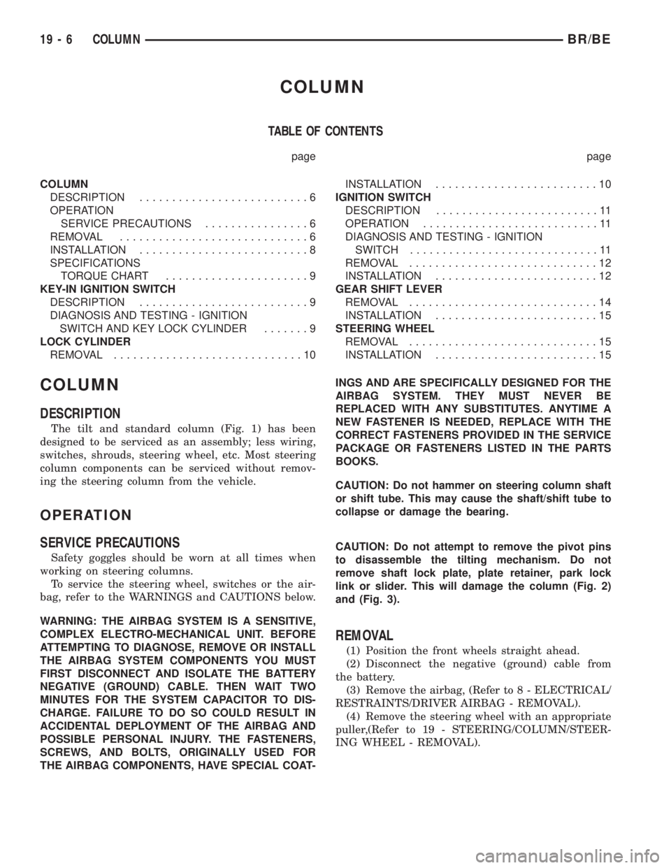
The tilt and standard column (Fig. 1) has been
designed to be serviced as an assembly; less wiring,
switches, shrouds, steering wheel, etc. Most steering
column components can be serviced without remov-
ing the steering column from the vehicle.
OPERATION
SERVICE PRECAUTIONS
Safety goggles should be worn at all times when
working on steering columns.
To service the steering wheel, switches or the air-
bag, refer to the WARNINGS and CAUTIONS below.
WARNING: THE AIRBAG SYSTEM IS A SENSITIVE,
COMPLEX ELECTRO-MECHANICAL UNIT. BEFORE
ATTEMPTING TO DIAGNOSE, REMOVE OR INSTALL
THE AIRBAG SYSTEM COMPONENTS YOU MUST
FIRST DISCONNECT AND ISOLATE THE BATTERY
NEGATIVE (GROUND) CABLE. THEN WAIT TWO
MINUTES FOR THE SYSTEM CAPACITOR TO DIS-
CHARGE. FAILURE TO DO SO COULD RESULT IN
ACCIDENTAL DEPLOYMENT OF THE AIRBAG AND
POSSIBLE PERSONAL INJURY. THE FASTENERS,
SCREWS, AND BOLTS, ORIGINALLY USED FOR
THE AIRBAG COMPONENTS, HAVE SPECIAL COAT-INGS AND ARE SPECIFICALLY DESIGNED FOR THE
AIRBAG SYSTEM. THEY MUST NEVER BE
REPLACED WITH ANY SUBSTITUTES. ANYTIME A
NEW FASTENER IS NEEDED, REPLACE WITH THE
CORRECT FASTENERS PROVIDED IN THE SERVICE
PACKAGE OR FASTENERS LISTED IN THE PARTS
BOOKS.
CAUTION: Do not hammer on steering column shaft
or shift tube. This may cause the shaft/shift tube to
collapse or damage the bearing.
CAUTION: Do not attempt to remove the pivot pins
to disassemble the tilting mechanism. Do not
remove shaft lock plate, plate retainer, park lock
link or slider. This will damage the column (Fig. 2)
and (Fig. 3).
REMOVAL
(1) Position the front wheels straight ahead.
(2) Disconnect the negative (ground) cable from
the battery.
(3) Remove the airbag, (Refer to 8 - ELECTRICAL/
RESTRAINTS/DRIVER AIRBAG - REMOVAL).
(4) Remove the steering wheel with an appropriate
puller,(Refer to 19 - STEERING/COLUMN/STEER-
ING WHEEL - REMOVAL).
19 - 6 COLUMNBR/BE
Page 1418 of 2255
(3) Remove the shipping lock pin if necessary.
(4) Install the column through the floor pan.
(5) Position the column bracket breakaway cap-
sules on the mounting studs. Install, butloose
assemblethe two upper bracket nuts.
(6) With the front wheels in the straight-ahead
position. Align steering column shaft to the coupler.
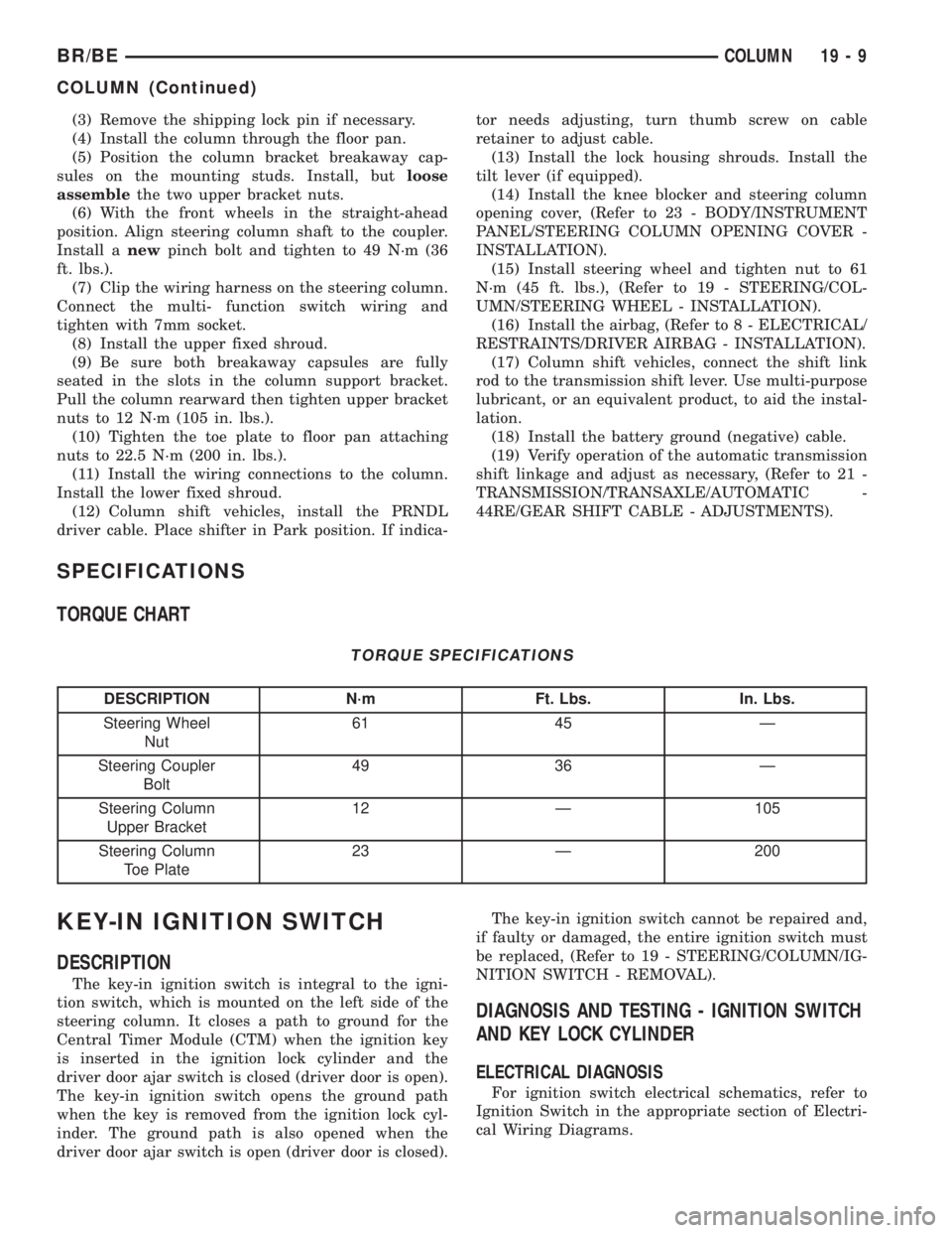
Install anewpinch bolt and tighten to 49 N´m (36
ft. lbs.).
(7) Clip the wiring harness on the steering column.
Connect the multi- function switch wiring and
tighten with 7mm socket.
(8) Install the upper fixed shroud.
(9) Be sure both breakaway capsules are fully
seated in the slots in the column support bracket.
Pull the column rearward then tighten upper bracket
nuts to 12 N´m (105 in. lbs.).
(10) Tighten the toe plate to floor pan attaching
nuts to 22.5 N´m (200 in. lbs.).
(11) Install the wiring connections to the column.
Install the lower fixed shroud.
(12) Column shift vehicles, install the PRNDL
driver cable. Place shifter in Park position. If indica-tor needs adjusting, turn thumb screw on cable
retainer to adjust cable.
(13) Install the lock housing shrouds. Install the
tilt lever (if equipped).
(14) Install the knee blocker and steering column
opening cover, (Refer to 23 - BODY/INSTRUMENT
PANEL/STEERING COLUMN OPENING COVER -
INSTALLATION).
(15) Install steering wheel and tighten nut to 61
N´m (45 ft. lbs.), (Refer to 19 - STEERING/COL-
UMN/STEERING WHEEL - INSTALLATION).
(16) Install the airbag, (Refer to 8 - ELECTRICAL/
RESTRAINTS/DRIVER AIRBAG - INSTALLATION).
(17) Column shift vehicles, connect the shift link
rod to the transmission shift lever. Use multi-purpose
lubricant, or an equivalent product, to aid the instal-
lation.
(18) Install the battery ground (negative) cable.
(19) Verify operation of the automatic transmission
shift linkage and adjust as necessary, (Refer to 21 -
TRANSMISSION/TRANSAXLE/AUTOMATIC -
44RE/GEAR SHIFT CABLE - ADJUSTMENTS).
SPECIFICATIONS
TORQUE CHART
TORQUE SPECIFICATIONS
DESCRIPTION N´m Ft. Lbs. In. Lbs.
Steering Wheel
Nut61 45 Ð
Steering Coupler
Bolt49 36 Ð
Steering Column
Upper Bracket12 Ð 105
Steering Column
Toe Plate23 Ð 200
KEY-IN IGNITION SWITCH
DESCRIPTION
The key-in ignition switch is integral to the igni-
tion switch, which is mounted on the left side of the
steering column. It closes a path to ground for the
Central Timer Module (CTM) when the ignition key
is inserted in the ignition lock cylinder and the
driver door ajar switch is closed (driver door is open).
The key-in ignition switch opens the ground path
when the key is removed from the ignition lock cyl-
inder. The ground path is also opened when the
driver door ajar switch is open (driver door is closed).The key-in ignition switch cannot be repaired and,
if faulty or damaged, the entire ignition switch must
be replaced, (Refer to 19 - STEERING/COLUMN/IG-
NITION SWITCH - REMOVAL).
DIAGNOSIS AND TESTING - IGNITION SWITCH
AND KEY LOCK CYLINDER
ELECTRICAL DIAGNOSIS
For ignition switch electrical schematics, refer to
Ignition Switch in the appropriate section of Electri-
cal Wiring Diagrams.
BR/BECOLUMN 19 - 9
COLUMN (Continued)
Page 1425 of 2255
GEAR
TABLE OF CONTENTS
page page
GEAR
DESCRIPTION.........................16
OPERATION...........................16
DIAGNOSIS AND TESTING - POWER
STEERING GEAR LEAKAGE.............16
REMOVAL.............................18
INSTALLATION.........................18
ADJUSTMENTS........................18
SPECIFICATIONS
POWER STEERING GEAR..............21
TORQUE CHART......................21
SPECIAL TOOLS
POWER STEERING GEAR..............22
PITMAN BEARING
REMOVAL.............................22
INSTALLATION.........................23PITMAN SHAFT
REMOVAL.............................24
INSTALLATION.........................25
PITMAN SHAFT SEAL
REMOVAL.............................25
INSTALLATION.........................26
SPOOL VALVE
REMOVAL.............................26
INSTALLATION.........................28
STEERING GEAR HOUSING PLUG
REMOVAL.............................29
INSTALLATION.........................30
WORM SHAFT
REMOVAL.............................30
INSTALLATION.........................31
GEAR
DESCRIPTION
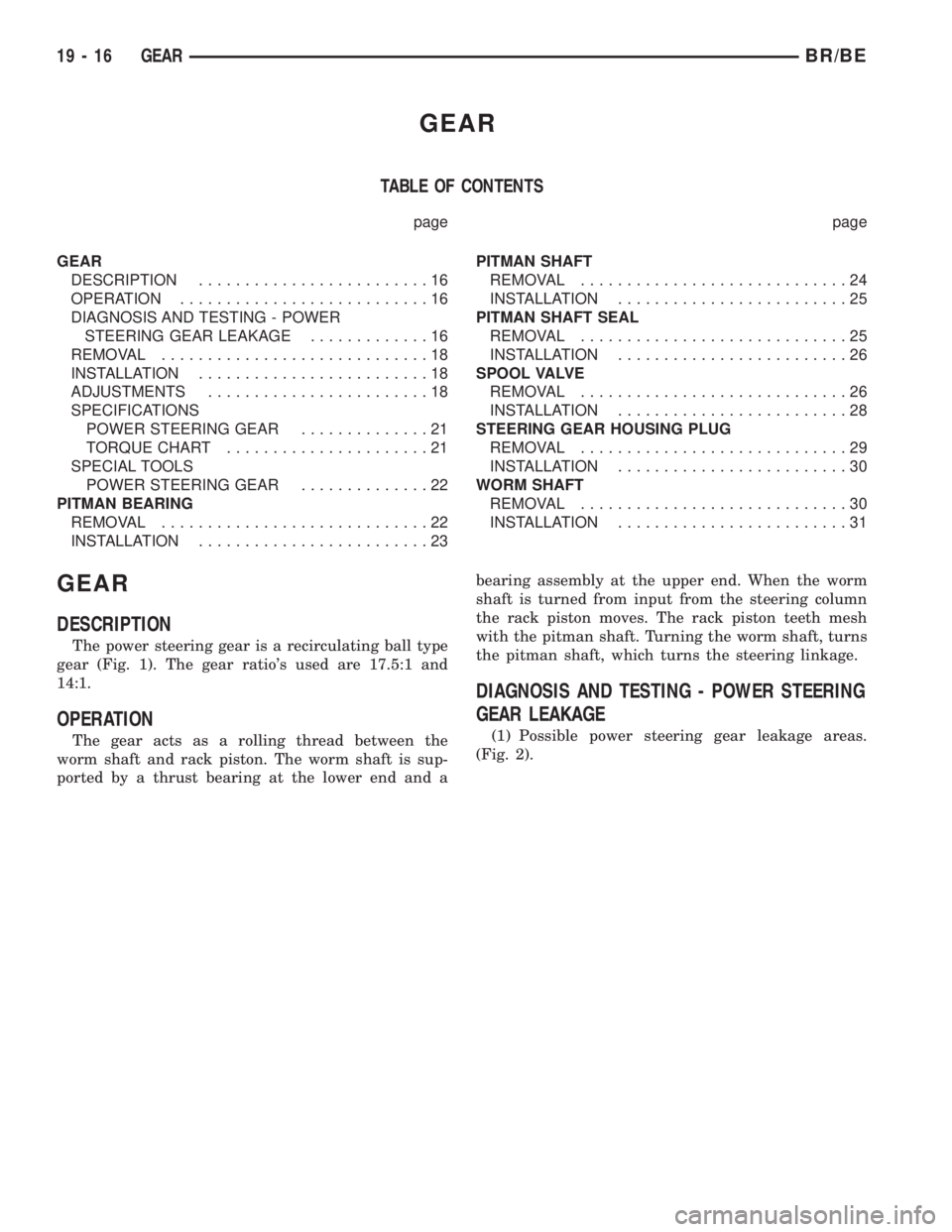
The power steering gear is a recirculating ball type
gear (Fig. 1). The gear ratio's used are 17.5:1 and
14:1.
OPERATION
The gear acts as a rolling thread between the
worm shaft and rack piston. The worm shaft is sup-
ported by a thrust bearing at the lower end and abearing assembly at the upper end. When the worm
shaft is turned from input from the steering column
the rack piston moves. The rack piston teeth mesh
with the pitman shaft. Turning the worm shaft, turns
the pitman shaft, which turns the steering linkage.
DIAGNOSIS AND TESTING - POWER STEERING
GEAR LEAKAGE
(1) Possible power steering gear leakage areas.
(Fig. 2).
19 - 16 GEARBR/BE
Page 1430 of 2255
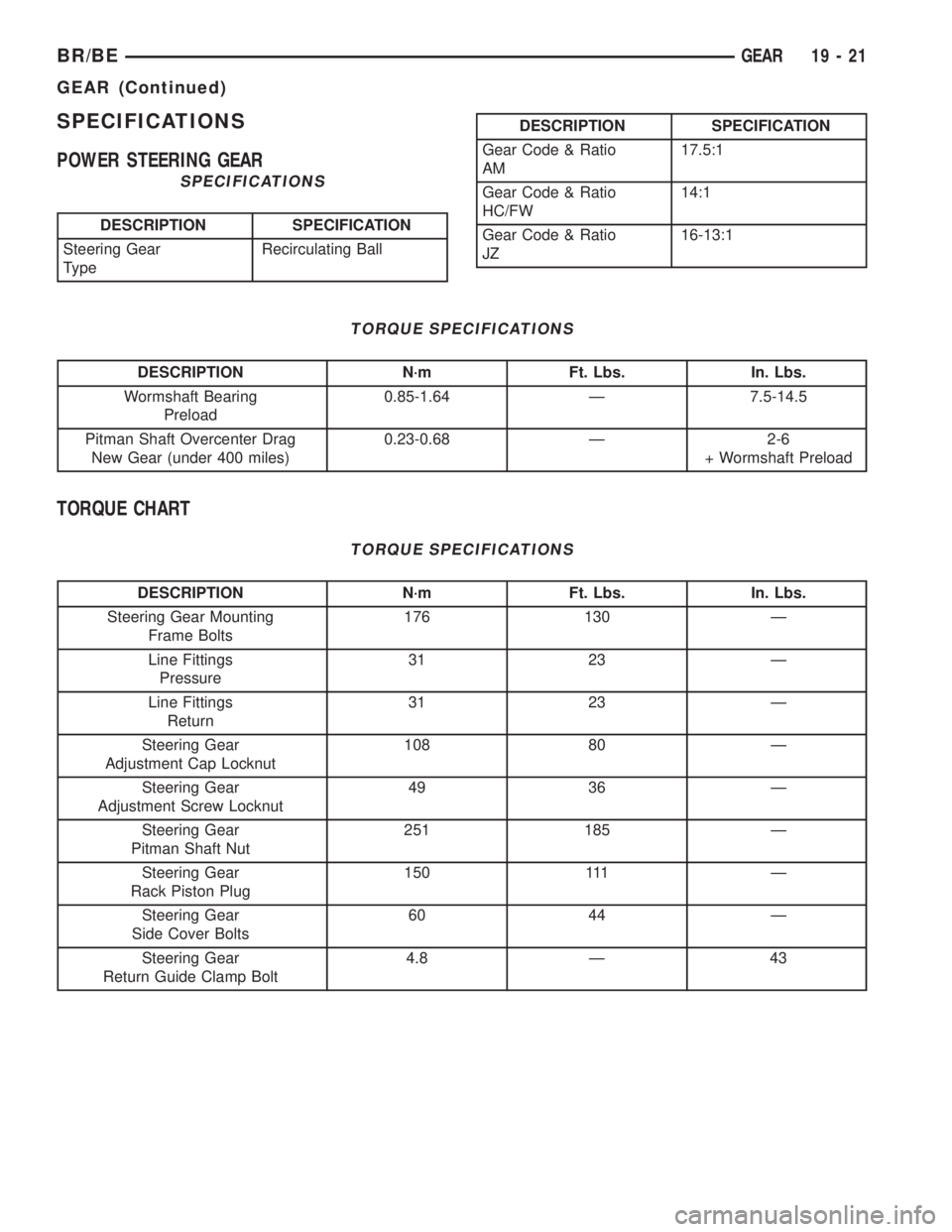
SPECIFICATIONS
POWER STEERING GEAR
SPECIFICATIONS
DESCRIPTION SPECIFICATION
Steering Gear
TypeRecirculating Ball
DESCRIPTION SPECIFICATION
Gear Code & Ratio
AM17.5:1
Gear Code & Ratio
HC/FW14:1
Gear Code & Ratio
JZ16-13:1
TORQUE SPECIFICATIONS
DESCRIPTION N´m Ft. Lbs. In. Lbs.
Wormshaft Bearing
Preload0.85-1.64 Ð 7.5-14.5
Pitman Shaft Overcenter Drag
New Gear (under 400 miles)0.23-0.68 Ð 2-6
+ Wormshaft Preload
TORQUE CHART
TORQUE SPECIFICATIONS
DESCRIPTION N´m Ft. Lbs. In. Lbs.
Steering Gear Mounting
Frame Bolts176 130 Ð
Line Fittings
Pressure31 23 Ð
Line Fittings
Return31 23 Ð
Steering Gear
Adjustment Cap Locknut108 80 Ð
Steering Gear
Adjustment Screw Locknut49 36 Ð
Steering Gear
Pitman Shaft Nut251 185 Ð
Steering Gear
Rack Piston Plug150 111 Ð
Steering Gear
Side Cover Bolts60 44 Ð
Steering Gear
Return Guide Clamp Bolt4.8 Ð 43
BR/BEGEAR 19 - 21
GEAR (Continued)