2002 DODGE RAM airbag disable
[x] Cancel search: airbag disablePage 2132 of 2255
LOCATING VACUUM LEAKS
WARNING: ON VEHICLES EQUIPPED WITH AIR-
BAGS, DISABLE THE AIRBAG SYSTEM BEFORE
ATTEMPTING ANY STEERING WHEEL, STEERING
COLUMN, OR INSTRUMENT PANEL COMPONENT
DIAGNOSIS OR SERVICE. DISCONNECT AND ISO-
LATE THE BATTERY NEGATIVE (GROUND) CABLE,
THEN WAIT TWO MINUTES FOR THE AIRBAG SYS-
TEM CAPACITOR TO DISCHARGE BEFORE PER-
FORMING FURTHER DIAGNOSIS OR SERVICE. THIS
IS THE ONLY SURE WAY TO DISABLE THE AIRBAG
SYSTEM. FAILURE TO TAKE THE PROPER PRE-
CAUTIONS COULD RESULT IN AN ACCIDENTAL
AIRBAG DEPLOYMENT AND POSSIBLE PERSONAL
INJURY.
(1) Disconnect the vacuum harness connector
located between the a/c heater control and the HVAC
housing under the instrument panel.
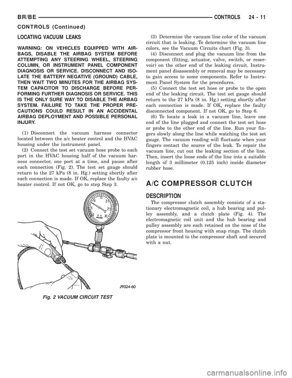
(2) Connect the test set vacuum hose probe to each
port in the HVAC housing half of the vacuum har-
ness connector, one port at a time, and pause after
each connection (Fig. 2). The test set gauge should
return to the 27 kPa (8 in. Hg.) setting shortly after
each connection is made. If OK, replace the faulty a/c
heater control. If not OK, go to step Step 3.(3) Determine the vacuum line color of the vacuum
circuit that is leaking. To determine the vacuum line
colors, see the Vacuum Circuits chart (Fig. 3).
(4) Disconnect and plug the vacuum line from the
component (fitting, actuator, valve, switch, or reser-
voir) on the other end of the leaking circuit. Instru-
ment panel disassembly or removal may be necessary
to gain access to some components. Refer to Instru-
ment Panel System for the procedures.
(5) Connect the test set hose or probe to the open
end of the leaking circuit. The test set gauge should
return to the 27 kPa (8 in. Hg.) setting shortly after
each connection is made. If OK, replace the faulty
disconnected component. If not OK, go to Step 6.
(6) To locate a leak in a vacuum line, leave one
end of the line plugged and connect the test set hose
or probe to the other end of the line. Run your fin-
gers slowly along the line while watching the test set
gauge. The vacuum reading will fluctuate when your
fingers contact the source of the leak. To repair the
vacuum line, cut out the leaking section of the line.
Then, insert the loose ends of the line into a suitable
length of 3 millimeter (0.125 inch) inside diameter
rubber hose.
A/C COMPRESSOR CLUTCH
DESCRIPTION
The compressor clutch assembly consists of a sta-
tionary electromagnetic coil, a hub bearing and pul-
ley assembly, and a clutch plate (Fig. 4). The
electromagnetic coil unit and the hub bearing and
pulley assembly are each retained on the nose of the
compressor front housing with snap rings. The clutch
plate is mounted to the compressor shaft and secured
with a nut.
Fig. 2 VACUUM CIRCUIT TEST
BR/BECONTROLS 24 - 11
CONTROLS (Continued)
Page 2140 of 2255
(3) On vehicles with air conditioning, turn the
temperature control knob to the extreme counter
clockwise (Cool) position, and set the mode control
switch knob to the Bi-Level (A/C) position. The out-
side (recirculation) air door should be open to outside
air. If not OK, (Refer to 24 - HEATING & AIR CON-
DITIONING/CONTROLS - DIAGNOSIS AND TEST-
ING - VACUUM SYSTEM).
(4) Open the vehicle windows. Test the blower
motor operation in all speeds. If not OK, (Refer to 24
- HEATING & AIR CONDITIONING/DISTRIBU-
TION/BLOWER MOTOR - DIAGNOSIS AND TEST-
ING).
(5) On vehicles with air conditioning, the compres-
sor should be running and the air conditioning sys-
tem in operation unless the ambient air temperature
is below about -1É C (30É F). If not OK, (Refer to 24 -
HEATING & AIR CONDITIONING - DIAGNOSIS
AND TESTING - A/C PERFORMANCE).
(6) Check the mode control switch operation. The
heater and air conditioner systems should respond as
described in the owner's manual in the vehicle glove
box to each mode selected. Reduce the engine speed
to normal idle. The vacuum will be high at low idle
and the vacuum actuators should respond quickly. If
not OK, (Refer to 24 - HEATING & AIR CONDI-
TIONING/CONTROLS - DIAGNOSIS AND TEST-
ING - VACUUM SYSTEM).
(7) If the vacuum tests, and the electrical compo-
nent and circuit tests reveal no problems, disassem-
ble the HVAC housing to inspect for mechanical
misalignment or binding of the mode doors (Refer to
24 - HEATING & AIR CONDITIONING/DISTRIBU-
TION/HVAC HOUSING - DISASSEMBLY)
REMOVAL
WARNING: ON VEHICLES EQUIPPED WITH AIR-
BAGS, DISABLE THE AIRBAG SYSTEM BEFORE
ATTEMPTING ANY STEERING WHEEL, STEERING
COLUMN, OR INSTRUMENT PANEL COMPONENT
DIAGNOSIS OR SERVICE. DISCONNECT AND ISO-
LATE THE BATTERY NEGATIVE (GROUND) CABLE,
THEN WAIT TWO MINUTES FOR THE AIRBAG SYS-
TEM CAPACITOR TO DISCHARGE BEFORE PER-
FORMING FURTHER DIAGNOSIS OR SERVICE. THIS
IS THE ONLY SURE WAY TO DISABLE THE AIRBAG
SYSTEM. FAILURE TO TAKE THE PROPER PRE-
CAUTIONS COULD RESULT IN AN ACCIDENTAL
AIRBAG DEPLOYMENT AND POSSIBLE PERSONAL
INJURY.
(1) Disconnect and isolate the battery negative
cable.
(2) Reach under the instrument panel near the
driver side of the floor panel transmission tunnel andunplug the a/c heater control to HVAC housing vac-
uum harness connector.
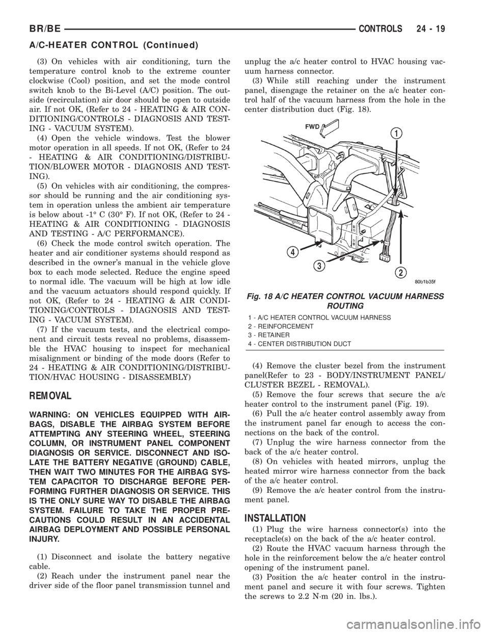
(3) While still reaching under the instrument
panel, disengage the retainer on the a/c heater con-
trol half of the vacuum harness from the hole in the
center distribution duct (Fig. 18).
(4) Remove the cluster bezel from the instrument
panel(Refer to 23 - BODY/INSTRUMENT PANEL/
CLUSTER BEZEL - REMOVAL).
(5) Remove the four screws that secure the a/c
heater control to the instrument panel (Fig. 19).
(6) Pull the a/c heater control assembly away from
the instrument panel far enough to access the con-
nections on the back of the control.
(7) Unplug the wire harness connector from the
back of the a/c heater control.
(8) On vehicles with heated mirrors, unplug the
heated mirror wire harness connector from the back
of the a/c heater control.
(9) Remove the a/c heater control from the instru-
ment panel.
INSTALLATION
(1) Plug the wire harness connector(s) into the
receptacle(s) on the back of the a/c heater control.
(2) Route the HVAC vacuum harness through the
hole in the reinforcement below the a/c heater control
opening of the instrument panel.
(3) Position the a/c heater control in the instru-
ment panel and secure it with four screws. Tighten
the screws to 2.2 N´m (20 in. lbs.).
Fig. 18 A/C HEATER CONTROL VACUUM HARNESS
ROUTING
1 - A/C HEATER CONTROL VACUUM HARNESS
2 - REINFORCEMENT
3 - RETAINER
4 - CENTER DISTRIBUTION DUCT
BR/BECONTROLS 24 - 19
A/C-HEATER CONTROL (Continued)
Page 2145 of 2255
WARNING: ON VEHICLES EQUIPPED WITH AIR-
BAGS, DISABLE THE AIRBAG SYSTEM BEFORE
ATTEMPTING ANY STEERING WHEEL, STEERING
COLUMN, OR INSTRUMENT PANEL COMPONENT
DIAGNOSIS OR SERVICE. DISCONNECT AND ISO-
LATE THE BATTERY NEGATIVE (GROUND) CABLE,
THEN WAIT TWO MINUTES FOR THE AIRBAG SYS-
TEM CAPACITOR TO DISCHARGE BEFORE PER-
FORMING FURTHER DIAGNOSIS OR SERVICE. THIS
IS THE ONLY SURE WAY TO DISABLE THE AIRBAG
SYSTEM. FAILURE TO TAKE THE PROPER PRE-
CAUTIONS COULD RESULT IN AN ACCIDENTAL
AIRBAG DEPLOYMENT AND POSSIBLE PERSONAL
INJURY.
(1) Disconnect and isolate the battery negative
cable.
(2) Unplug the wire harness connector from the
blower motor resistor.
(3) Check for continuity between each of the
blower motor switch input terminals of the resistor
and the resistor output terminal. In each case there
should be continuity. If OK, repair the wire harness
circuits between the blower motor switch and the
blower motor resistor or blower motor as required. If
not OK, replace the faulty blower motor resistor.
REMOVAL
WARNING: ON VEHICLES EQUIPPED WITH AIR-
BAGS, DISABLE THE AIRBAG SYSTEM BEFORE
ATTEMPTING ANY STEERING WHEEL, STEERING
COLUMN, OR INSTRUMENT PANEL COMPONENT
DIAGNOSIS OR SERVICE. DISCONNECT AND ISO-
LATE THE BATTERY NEGATIVE (GROUND) CABLE,
THEN WAIT TWO MINUTES FOR THE AIRBAG SYS-
TEM CAPACITOR TO DISCHARGE BEFORE PER-
FORMING FURTHER DIAGNOSIS OR SERVICE. THIS
IS THE ONLY SURE WAY TO DISABLE THE AIRBAG
SYSTEM. FAILURE TO TAKE THE PROPER PRE-
CAUTIONS COULD RESULT IN AN ACCIDENTAL
AIRBAG DEPLOYMENT AND POSSIBLE PERSONAL
INJURY.
(1) Disconnect and isolate the battery negative
cable.
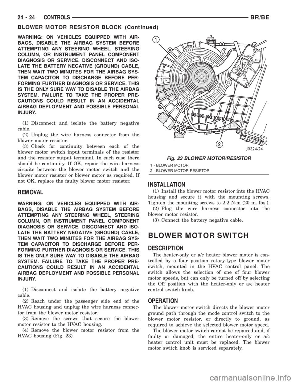
(2) Reach under the passenger side end of the
HVAC housing and unplug the wire harness connec-
tor from the blower motor resistor.
(3) Remove the screws that secure the blower
motor resistor to the HVAC housing.
(4) Remove the blower motor resistor from the
HVAC housing (Fig. 23).
INSTALLATION
(1) Install the blower motor resistor into the HVAC
housing and secure it with the mounting screws.
Tighten the mounting screws to 2.2 N´m (20 in. lbs.).
(2) Plug the wire harness connector into the
blower motor resistor.
(3) Connect the battery negative cable.
BLOWER MOTOR SWITCH
DESCRIPTION
The heater-only or a/c heater blower motor is con-
trolled by a four position rotary-type blower motor
switch, mounted in the HVAC control panel. The
switch allows the selection of one of four blower
motor speeds, but can only be turned off by selecting
the Off position with the heater-only or a/c heater
control switch knob.
OPERATION
The blower motor switch directs the blower motor
ground path through the mode control switch to the
blower motor resistor, or directly to ground, as
required to achieve the selected blower motor speed.
The blower motor switch cannot be repaired and, if
faulty or damaged, the entire heater-only or a/c
heater control unit must be replaced. The blower
motor switch knob is serviced separately.
Fig. 23 BLOWER MOTOR/RESISTOR
1 - BLOWER MOTOR
2 - BLOWER MOTOR RESISTOR
24 - 24 CONTROLSBR/BE
BLOWER MOTOR RESISTOR BLOCK (Continued)
Page 2146 of 2255
DIAGNOSIS AND TESTING - BLOWER MOTOR
SWITCH
For circuit descriptions and diagrams, (Refer to
Appropriate Wiring Information).
WARNING: ON VEHICLES EQUIPPED WITH AIR-
BAGS, DISABLE THE AIRBAG SYSTEM BEFORE
ATTEMPTING ANY STEERING WHEEL, STEERING
COLUMN, OR INSTRUMENT PANEL COMPONENT
DIAGNOSIS OR SERVICE. DISCONNECT AND ISO-
LATE THE BATTERY NEGATIVE (GROUND) CABLE,
THEN WAIT TWO MINUTES FOR THE AIRBAG SYS-
TEM CAPACITOR TO DISCHARGE BEFORE PER-
FORMING FURTHER DIAGNOSIS OR SERVICE. THIS
IS THE ONLY SURE WAY TO DISABLE THE AIRBAG
SYSTEM. FAILURE TO TAKE THE PROPER PRE-
CAUTIONS COULD RESULT IN AN ACCIDENTAL
AIRBAG DEPLOYMENT AND POSSIBLE PERSONAL
INJURY.
(1) Check for battery voltage at the fuse in the
Power Distribution Center (PDC). If OK, go to Step
2. If not OK, repair the shorted circuit or component
as required and replace the faulty fuse.
(2) Turn the ignition switch to the Off position.
Disconnect and isolate the battery negative cable.
Remove the a/c heater control from the instrument
panel. (Refer to 24 - HEATING & AIR CONDITION-
ING/CONTROLS/A/C HEATER CONTROL -
REMOVAL) Check for continuity between the ground
circuit cavity of the a/c heater control wire harness
connector and a good ground. There should be conti-
nuity. If OK, go to Step 3. If not OK, repair the open
circuit to ground as required.
(3) With the a/c heater control wire harness con-
nector unplugged, place the a/c heater mode control
switch knob in any position except the Off position.
Check for continuity between the ground circuit ter-
minal and each of the blower motor driver circuit ter-
minals of the a/c heater control as you move the
blower motor switch knob to each of the four speed
positions. There should be continuity at each driver
circuit terminal in only one blower motor switch
speed position. If OK, test and repair the blower
driver circuits between the a/c heater control connec-
tor and the blower motor resistor as required. If not
OK, replace the faulty a/c heater control unit.
REMOVAL
The blower motor switch cannot be repaired and, if
faulty or damaged, the entire heater-only or a/c
heater control unit must be replaced. (Refer to 24 -
HEATING & AIR CONDITIONING/CONTROLS/A/C
HEATER CONTROL - REMOVAL) The blower motor
switch knob is serviced separately.
BLEND DOOR ACTUATOR
REMOVAL
WARNING: ON VEHICLES EQUIPPED WITH AIR-
BAGS, DISABLE THE AIRBAG SYSTEM BEFORE
ATTEMPTING ANY STEERING WHEEL, STEERING
COLUMN, OR INSTRUMENT PANEL COMPONENT
DIAGNOSIS OR SERVICE. DISCONNECT AND ISO-
LATE THE BATTERY NEGATIVE (GROUND) CABLE,
THEN WAIT TWO MINUTES FOR THE AIRBAG SYS-
TEM CAPACITOR TO DISCHARGE BEFORE PER-
FORMING FURTHER DIAGNOSIS OR SERVICE. THIS
IS THE ONLY SURE WAY TO DISABLE THE AIRBAG
SYSTEM. FAILURE TO TAKE THE PROPER PRE-
CAUTIONS COULD RESULT IN AN ACCIDENTAL
AIRBAG DEPLOYMENT AND POSSIBLE PERSONAL
INJURY.
(1) Turn the ignition switch to the run position.
(2) Locate the temperature control knob in the mid
(12 o'clock) position.
(3) Turn the ignition switch to the off position.
(4) Disconnect and isolate the battery negative
cable.
(5) Remove the instrument panel from the vehi-
cle(Refer to 23 - BODY/INSTRUMENT PANEL/IN-
STRUMENT PANEL ASSEMBLY - REMOVAL).
(6) Remove the HVAC housing from the vehicle.
(Refer to 24 - HEATING & AIR CONDITIONING/
DISTRIBUTION/HVAC HOUSING - REMOVAL)
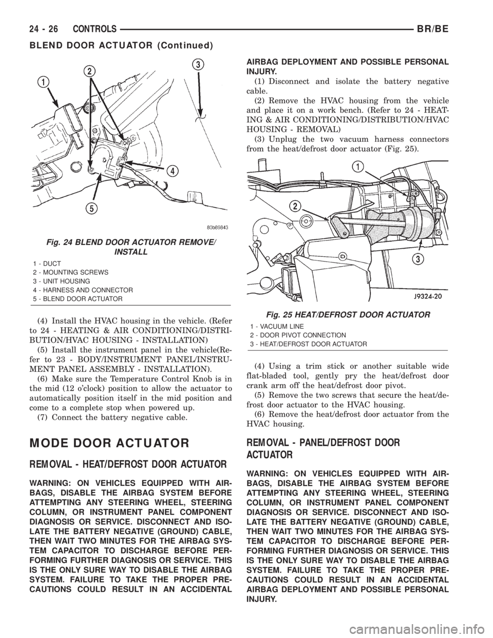
(7) Unplug the wire harness connector from the
blend door actuator (Fig. 24).
(8) Remove the two mounting screws which secure
the actuator to the housing.
(9) Slide the blend door actuator off the blend door
shaft.
NOTE: A black plastic coupler may be attached to
the blend door shaft. Remove the coupler and
inspect for damage. Reinstall if there is no damage
found.
INSTALLATION
NOTE: Before installing the blend door actuator, be
certain that the blend door is not binding and is
capable of full travel in both directions.
(1) Align the actuator with the blend door shaft
and rotate the actuator to align it to the mounting
bosses on the HVAC housing.
(2) Align and install the actuator screws. Tighten
the mounting screws to 2.2 N´m (20 in. lbs.).
(3) Plug in the wire harness connector to the blend
door actuator.
BR/BECONTROLS 24 - 25
BLOWER MOTOR SWITCH (Continued)
Page 2147 of 2255
(4) Install the HVAC housing in the vehicle. (Refer
to 24 - HEATING & AIR CONDITIONING/DISTRI-
BUTION/HVAC HOUSING - INSTALLATION)
(5) Install the instrument panel in the vehicle(Re-
fer to 23 - BODY/INSTRUMENT PANEL/INSTRU-
MENT PANEL ASSEMBLY - INSTALLATION).
(6) Make sure the Temperature Control Knob is in
the mid (12 o'clock) position to allow the actuator to
automatically position itself in the mid position and
come to a complete stop when powered up.
(7) Connect the battery negative cable.
MODE DOOR ACTUATOR
REMOVAL - HEAT/DEFROST DOOR ACTUATOR
WARNING: ON VEHICLES EQUIPPED WITH AIR-
BAGS, DISABLE THE AIRBAG SYSTEM BEFORE
ATTEMPTING ANY STEERING WHEEL, STEERING
COLUMN, OR INSTRUMENT PANEL COMPONENT
DIAGNOSIS OR SERVICE. DISCONNECT AND ISO-
LATE THE BATTERY NEGATIVE (GROUND) CABLE,
THEN WAIT TWO MINUTES FOR THE AIRBAG SYS-
TEM CAPACITOR TO DISCHARGE BEFORE PER-
FORMING FURTHER DIAGNOSIS OR SERVICE. THIS
IS THE ONLY SURE WAY TO DISABLE THE AIRBAG
SYSTEM. FAILURE TO TAKE THE PROPER PRE-
CAUTIONS COULD RESULT IN AN ACCIDENTALAIRBAG DEPLOYMENT AND POSSIBLE PERSONAL
INJURY.
(1) Disconnect and isolate the battery negative
cable.
(2) Remove the HVAC housing from the vehicle
and place it on a work bench. (Refer to 24 - HEAT-
ING & AIR CONDITIONING/DISTRIBUTION/HVAC
HOUSING - REMOVAL)
(3) Unplug the two vacuum harness connectors
from the heat/defrost door actuator (Fig. 25).
(4) Using a trim stick or another suitable wide
flat-bladed tool, gently pry the heat/defrost door
crank arm off the heat/defrost door pivot.
(5) Remove the two screws that secure the heat/de-
frost door actuator to the HVAC housing.
(6) Remove the heat/defrost door actuator from the
HVAC housing.
REMOVAL - PANEL/DEFROST DOOR
ACTUATOR
WARNING: ON VEHICLES EQUIPPED WITH AIR-
BAGS, DISABLE THE AIRBAG SYSTEM BEFORE
ATTEMPTING ANY STEERING WHEEL, STEERING
COLUMN, OR INSTRUMENT PANEL COMPONENT
DIAGNOSIS OR SERVICE. DISCONNECT AND ISO-
LATE THE BATTERY NEGATIVE (GROUND) CABLE,
THEN WAIT TWO MINUTES FOR THE AIRBAG SYS-
TEM CAPACITOR TO DISCHARGE BEFORE PER-
FORMING FURTHER DIAGNOSIS OR SERVICE. THIS
IS THE ONLY SURE WAY TO DISABLE THE AIRBAG
SYSTEM. FAILURE TO TAKE THE PROPER PRE-
CAUTIONS COULD RESULT IN AN ACCIDENTAL
AIRBAG DEPLOYMENT AND POSSIBLE PERSONAL
INJURY.
Fig. 24 BLEND DOOR ACTUATOR REMOVE/
INSTALL
1 - DUCT
2 - MOUNTING SCREWS
3 - UNIT HOUSING
4 - HARNESS AND CONNECTOR
5 - BLEND DOOR ACTUATOR
Fig. 25 HEAT/DEFROST DOOR ACTUATOR
1 - VACUUM LINE
2 - DOOR PIVOT CONNECTION
3 - HEAT/DEFROST DOOR ACTUATOR
24 - 26 CONTROLSBR/BE
BLEND DOOR ACTUATOR (Continued)
Page 2148 of 2255

(1) Disconnect and isolate the battery negative
cable.
(2) Remove the instrument panel assembly from
the vehicle(Refer to 23 - BODY/INSTRUMENT PAN-
EL/INSTRUMENT PANEL ASSEMBLY - REMOV-
AL).
(3) Unplug the vacuum harness connector from the
panel/defrost door actuator (Fig. 26).
(4) Using a trim stick or another suitable wide
flat-bladed tool, gently pry the panel/defrost door
crank arm off the panel/defrost door pivot.
(5) Remove the two screws that secure the panel/
defrost door actuator to the HVAC housing.
(6) Remove the panel/defrost door actuator from
the HVAC housing.
INSTALLATION - HEAT/DEFROST DOOR
ACTUATOR
NOTE: Before installing the heat/defrost door actua-
tor, be certain that the heat/defrost door is not bind-
ing.
(1) Install the heat/defrost door actuator from the
HVAC housing. Tighten the actuator mounting
screws to 2.2 N´m (20 in. lbs.).
(2) Carefully snap the heat/defrost door crank arm
on the heat/defrost door pivot.(3) Plug in the two vacuum harness connectors to
the heat/defrost door actuator.
(4) Install the HVAC housing in the vehicle. (Refer
to 24 - HEATING & AIR CONDITIONING/DISTRI-
BUTION/HVAC HOUSING - INSTALLATION)
(5) Connect the battery negative cable.
INSTALLATION - PANEL/DEFROST DOOR
ACTUATOR
NOTE: Before installing the panel/defrost door
actuator, be certain that the panel/defrost door is
not binding.
(1) Install the panel/defrost door actuator on the
HVAC housing. Tighten the mounting screws to 2.2
N´m (20 in. lbs.).
(2) Carefully snap the panel/defrost door crank
arm on the panel/defrost door pivot.
(3) Plug the vacuum harness connector to the pan-
el/defrost door actuator.
(4) Install the instrument panel assembly in the
vehicle(Refer to 23 - BODY/INSTRUMENT PANEL/
INSTRUMENT PANEL ASSEMBLY - INSTALLA-
TION).
(5) Connect the battery negative cable.
RECIRCULATION DOOR
ACTUATOR
REMOVAL
WARNING: ON VEHICLES EQUIPPED WITH AIR-
BAGS, DISABLE THE AIRBAG SYSTEM BEFORE
ATTEMPTING ANY STEERING WHEEL, STEERING
COLUMN, OR INSTRUMENT PANEL COMPONENT
DIAGNOSIS OR SERVICE. DISCONNECT AND ISO-
LATE THE BATTERY NEGATIVE (GROUND) CABLE,
THEN WAIT TWO MINUTES FOR THE AIRBAG SYS-
TEM CAPACITOR TO DISCHARGE BEFORE PER-
FORMING FURTHER DIAGNOSIS OR SERVICE. THIS
IS THE ONLY SURE WAY TO DISABLE THE AIRBAG
SYSTEM. FAILURE TO TAKE THE PROPER PRE-
CAUTIONS COULD RESULT IN AN ACCIDENTAL
AIRBAG DEPLOYMENT AND POSSIBLE PERSONAL
INJURY.
(1) Disconnect and isolate the battery negative
cable.
(2) Remove the glove box from the instrument pan-
el(Refer to 23 - BODY/INSTRUMENT PANEL/IN-
STRUMENT PANEL ASSEMBLY - REMOVAL).
Fig. 26 PANEL/DEFROST DOOR ACTUATOR
1 - VACUUM LINE
2 - PANEL/DEFROST ACTUATOR
3 - SHAFT RETAINER
BR/BECONTROLS 24 - 27
MODE DOOR ACTUATOR (Continued)
Page 2153 of 2255
DIAGNOSIS AND TESTING - BLOWER MOTOR
WARNING: ON VEHICLES EQUIPPED WITH AIR-
BAGS, DISABLE THE AIRBAG SYSTEM BEFORE
ATTEMPTING ANY STEERING WHEEL, STEERING
COLUMN, OR INSTRUMENT PANEL COMPONENT
DIAGNOSIS OR SERVICE. DISCONNECT AND ISO-
LATE THE BATTERY NEGATIVE (GROUND) CABLE,
THEN WAIT TWO MINUTES FOR THE AIRBAG SYS-
TEM CAPACITOR TO DISCHARGE BEFORE PER-
FORMING FURTHER DIAGNOSIS OR SERVICE. THIS
IS THE ONLY SURE WAY TO DISABLE THE AIRBAG
SYSTEM. FAILURE TO TAKE THE PROPER PRE-
CAUTIONS COULD RESULT IN AN ACCIDENTAL
AIRBAG DEPLOYMENT AND POSSIBLE PERSONAL
INJURY.
For circuit descriptions and diagrams, (Refer to
Appropriate Wiring Information). Possible causes of
an inoperative blower motor include:
²Faulty fuse
²Faulty blower motor circuit wiring or wire har-
ness connectors
²Faulty blower motor resistor
²Faulty blower motor relay
²Faulty blower motor switch
²Faulty a/c heater mode control switch
²Faulty blower motor.
Possible causes of the blower motor not operating
in all speeds include:
²Faulty fuse
²Faulty blower motor switch
²Faulty blower motor resistor
²Faulty blower motor relay
²Faulty blower motor circuit wiring or wire har-
ness connectors.
VIBRATION
Possible causes of blower motor vibration include:
²Improper blower motor mounting
²Improper blower wheel mounting
²Blower wheel out of balance or deformed
²Blower motor faulty.
NOISE
To verify that the blower is the source of the noise,
unplug the blower motor wire harness connector and
operate the HVAC system. If the noise goes away,
possible causes include:
²Foreign material in the HVAC housing
²Improper blower motor mounting
²Improper blower wheel mounting
²Blower motor faulty.
REMOVAL
(1) Disconnect and isolate the battery negative
cable.
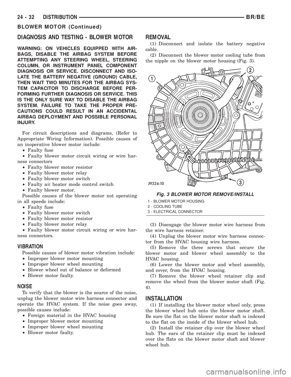
(2) Disconnect the blower motor cooling tube from
the nipple on the blower motor housing (Fig. 3).
(3) Disengage the blower motor wire harness from
the wire harness retainer.
(4) Unplug the blower motor wire harness connec-
tor from the HVAC housing wire harness.
(5) Remove the three screws that secure the
blower motor and blower wheel assembly to the
HVAC housing.
(6) Lower the blower motor and wheel assembly,
and cover, from the HVAC housing.
(7) Remove the blower wheel retainer clip and
remove the wheel from the blower motor shaft (Fig.
4).
INSTALLATION
(1) If installing the blower motor wheel only, press
the blower wheel hub onto the blower motor shaft.
Be sure the flat on the blower motor shaft is indexed
to the flat on the inside of the blower wheel hub.
(2) Install the retainer clip over the blower wheel
hub. The ears of the retainer clip must be indexed
over the flats on the blower motor shaft and blower
wheel hub.
Fig. 3 BLOWER MOTOR REMOVE/INSTALL
1 - BLOWER MOTOR HOUSING
2 - COOLING TUBE
3 - ELECTRICAL CONNECTOR
24 - 32 DISTRIBUTIONBR/BE
BLOWER MOTOR (Continued)
Page 2155 of 2255
(2) Roll the instrument panel assembly up, and
fasten it properly to the vehicle(Refer to 23 - BODY/
INSTRUMENT PANEL/INSTRUMENT PANEL
ASSEMBLY - INSTALLATION).
HVAC HOUSING
REMOVAL
WARNING: ON VEHICLES EQUIPPED WITH AIR-
BAGS, DISABLE THE AIRBAG SYSTEM BEFORE
ATTEMPTING ANY STEERING WHEEL, STEERING
COLUMN, OR INSTRUMENT PANEL COMPONENT
DIAGNOSIS OR SERVICE. DISCONNECT AND ISO-
LATE THE BATTERY NEGATIVE (GROUND) CABLE,
THEN WAIT TWO MINUTES FOR THE AIRBAG SYS-
TEM CAPACITOR TO DISCHARGE BEFORE PER-
FORMING FURTHER DIAGNOSIS OR SERVICE. THIS
IS THE ONLY SURE WAY TO DISABLE THE AIRBAG
SYSTEM. FAILURE TO TAKE THE PROPER PRE-
CAUTIONS COULD RESULT IN AN ACCIDENTAL
AIRBAG DEPLOYMENT AND POSSIBLE PERSONAL
INJURY.
WARNING: IF THE VEHICLE IS EQUIPPED WITH AIR
CONDITIONING, REVIEW THE WARNINGS AND
CAUTIONS IN PLUMBING BEFORE PERFORMING
THE FOLLOWING OPERATION. (Refer to 24 - HEAT-
ING & AIR CONDITIONING/PLUMBING - WARNING)
(Refer to 24 - HEATING & AIR CONDITIONING/
PLUMBING - CAUTION)
The HVAC housing assembly must be removed
from the vehicle and disassembled for service access
of the heater core, a/c evaporator, and each of the
various mode control doors.
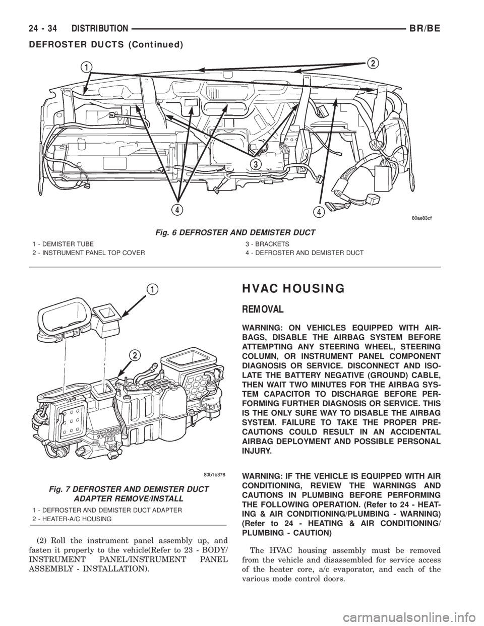
Fig. 6 DEFROSTER AND DEMISTER DUCT
1 - DEMISTER TUBE
2 - INSTRUMENT PANEL TOP COVER3 - BRACKETS
4 - DEFROSTER AND DEMISTER DUCT
Fig. 7 DEFROSTER AND DEMISTER DUCT
ADAPTER REMOVE/INSTALL
1 - DEFROSTER AND DEMISTER DUCT ADAPTER
2 - HEATER-A/C HOUSING
24 - 34 DISTRIBUTIONBR/BE
DEFROSTER DUCTS (Continued)