2002 DODGE RAM ECO mode
[x] Cancel search: ECO modePage 647 of 2255
However, these tests may not prove conclusive in the
diagnosis of this system on models equipped with a
high-line or premium Central Timer Module (CTM).
In order to obtain conclusive testing of the wiper sys-
tem on models with a high-line or premium CTM, the
Chrysler Collision Detection (CCD) data bus network
and all of the electronic modules that provide inputs
to or receive outputs from the wiper system compo-
nents must be checked. The most reliable, efficient,
and accurate means to diagnose the wiper system on
models with a high-line or premium CTM requires
the use of a DRBIIItscan tool. Refer to the appro-
priate diagnostic information. The DRBIIItscan tool
can provide confirmation that the CCD data bus is
functional, that all of the electronic modules are
sending and receiving the proper messages on the
CCD data bus, and that the wiper relay is being sent
the proper hard wired outputs by the CTM for it to
perform its wiper system functions.
WARNING: ON VEHICLES EQUIPPED WITH AIR-
BAGS, DISABLE THE AIRBAG SYSTEM BEFORE
ATTEMPTING ANY STEERING WHEEL, STEERING
COLUMN, OR INSTRUMENT PANEL COMPONENT
DIAGNOSIS OR SERVICE. DISCONNECT AND ISO-
LATE THE BATTERY NEGATIVE (GROUND) CABLE,
THEN WAIT TWO MINUTES FOR THE AIRBAG SYS-
TEM CAPACITOR TO DISCHARGE BEFORE PER-
FORMING FURTHER DIAGNOSIS OR SERVICE. THIS
IS THE ONLY SURE WAY TO DISABLE THE AIRBAG
SYSTEM. FAILURE TO TAKE THE PROPER PRE-
CAUTIONS COULD RESULT IN ACCIDENTAL AIR-
BAG DEPLOYMENT AND POSSIBLE PERSONAL
INJURY.
(1) Check the fused ignition switch output (run-
acc) fuse (Fuse6-25ampere) in the Junction Block
(JB). If OK, go to Step 2. If not OK, repair the
shorted circuit or component as required and replace
the faulty fuse.
(2) Turn the ignition switch to the On position.
Check for battery voltage at the fused ignition switch
output (run-acc) fuse (Fuse6-25ampere) in the JB.
If OK, go to Step 3. If not OK, repair the open fused
ignition switch output (run-acc) circuit between the
JB and the ignition switch as required.
(3) Turn the ignition switch to the Off position.
Disconnect and isolate the battery negative cable.
Disconnect the instrument panel wire harness con-
nector for the multi-function switch from the switch
connector receptacle. Reconnect the battery negative
cable. Turn the ignition switch to the On position.
Check for battery voltage at the fused ignition switch
output (run-acc) circuit cavity of the instrument
panel wire harness connector for the multi-function
switch. If OK, go to Step 4. If not OK, repair theopen fused ignition switch output circuit between the
multi-function switch and the JB as required.
(4) If the problem being diagnosed involves only
the intermittent wipe feature, go to Step 5. If the
problem being diagnosed involves all wiper modes, or
only the Low and/or High speed modes, go to Step 7.
(5) Turn the ignition switch to the Off position.
Disconnect and isolate the battery negative cable.
Disconnect the instrument panel wire harness con-
nector (Connector C1) for the Central Timer Module
(CTM) from the CTM connector receptacle. Check for
continuity between the wiper switch mode sense cir-
cuit cavities of the instrument panel wire harness
connector for the multi-function switch and the
instrument panel wire harness connector (Connector
C1) for the CTM. There should be continuity. If OK,
go to Step 6. If not OK, repair the open wiper switch
mode sense circuit between the multi-function switch
and the CTM as required.
(6) Check for continuity between the wiper switch
mode signal circuit cavities of the instrument panel
wire harness connector for the multi-function switch
and the instrument panel wire harness connector
(Connector C1) for the CTM. There should be conti-
nuity. If OK, proceed to the diagnosis for the wiper
relay. (Refer to 8 - ELECTRICAL/WIPERS/WASH-
ERS/WIPER RELAY - DIAGNOSIS AND TESTING).
If not OK, repair the open wiper switch mode signal
circuit between the multi-function switch and the
CTM as required.
(7) Check for continuity between the two wiper
switch low speed output circuit cavities of the instru-
ment panel wire harness connector for the multi-
function switch. There should be continuity. If OK, go
to Step 8. If not OK, repair the open wiper switch
low speed output circuit between the two cavities of
the instrument panel wire harness connector for the
multi-function switch as required.
(8) Test the multi-function switch continuity.
(Refer to 8 - ELECTRICAL/LAMPS/LIGHTING -
EXTERIOR/MULTI-FUNCTION SWITCH - DIAG-
NOSIS AND TESTING). If the multi-function switch
tests OK, reconnect the instrument panel wire har-
ness connector for the multi-function switch to the
switch connector receptacle and go to Step 9. If not
OK, replace the faulty multi-function switch and test
the wiper system operation again. If still not OK, go
to Step 9.
(9) Turn the ignition switch to the Off position.
Disconnect and isolate the battery negative cable.
Measure the resistance between the headlamp and
dash wire harness ground wire for the wiper motor
and a good ground. The meter should read zero
ohms. If OK, go to Step 10. If not OK, repair the
open ground circuit to ground (G100) as required.
8R - 4 WIPERS/WASHERSBR/BE
WIPERS/WASHERS (Continued)
Page 667 of 2255

SYMBOLS
International symbols are used throughout the wir-
ing diagrams. These symbols are consistent with
those being used around the world (Fig. 3).
TERMINOLOGY
This is a list of terms and definitions used in the
wiring diagrams.
LHD .................Left Hand Drive Vehicles
RHD................Right Hand Drive Vehicles
ATX . . Automatic Transmissions-Front Wheel Drive
MTX....Manual Transmissions-Front Wheel Drive
AT ....Automatic Transmissions-Rear Wheel Drive
MT .....Manual Transmissions-Rear Wheel Drive
SOHC...........Single Over Head Cam Engine
DOHC..........Double Over Head Cam Engine
Built-Up-Export........ Vehicles Built For Sale In
Markets Other Than North America
Except-Built-Up-Export . . Vehicles Built For Sale In
North America
DESCRIPTION - CIRCUIT INFORMATION
Each wire shown in the diagrams contains a code
which identifies the main circuit, part of the main
circuit, gage of wire, and color (Fig. 4).
WIRE COLOR CODE CHART
COLOR CODE COLOR
BL BLUE
BK BLACK
BR BROWN
DB DARK BLUE
DG DARK GREEN
GY GRAY
LB LIGHT BLUE
LG LIGHT GREEN
OR ORANGE
PK PINK
RD RED
TN TAN
VT VIOLET
WT WHITE
YL YELLOW
* WITH TRACER
DESCRIPTION - CIRCUIT FUNCTIONS
All circuits in the diagrams use an alpha/numeric
code to identify the wire and it's function. To identify
which circuit code applies to a system, refer to the
Circuit Identification Code Chart. This chart shows
the main circuits only and does not show the second-
ary codes that may apply to some models.
CIRCUIT IDENTIFICATION CODE CHART
CIRCUIT FUNCTION
A BATTERY FEED
B BRAKE CONTROLS
C CLIMATE CONTROLS
D DIAGNOSTIC CIRCUITS
E DIMMING ILLUMINATION
CIRCUITS
F FUSED CIRCUITS
G MONITORING CIRCUITS
(GAUGES)
H OPEN
I NOT USED
J OPEN
K POWERTRAIN CONTROL
MODULE
L EXTERIOR LIGHTING
M INTERIOR LIGHTING
N NOT USED
O NOT USED
P POWER OPTION (BATTERY
FEED)
Q POWER OPTIONS (IGNITION
FEED)
R PASSIVE RESTRAINT
S SUSPENSION/STEERING
T TRANSMISSION/TRANSAXLE/
TRANSFER CASE
U OPEN
V SPEED CONTROL, WIPER/
WASHER
W OPEN
X AUDIO SYSTEMS
Y OPEN
Z GROUNDS
8W - 01 - 4 8W-01 WIRING DIAGRAM INFORMATIONBR/BE
WIRING DIAGRAM INFORMATION (Continued)
Page 1061 of 2255
tribution points for the electrical current required to
operate all of the many standard and optional facto-
ry-installed electrical and electronic powertrain,
chassis, safety, security, comfort and convenience sys-
tems. At the same time, the power distribution sys-
tem was designed to provide ready access to these
electrical distribution points for the vehicle techni-
cian to use when conducting diagnosis and repair of
faulty circuits. The power distribution system can
also prove useful for the sourcing of additional elec-
trical circuits that may be required to provide the
electrical current needed to operate many accessories
that the vehicle owner may choose to have installed
in the aftermarket.
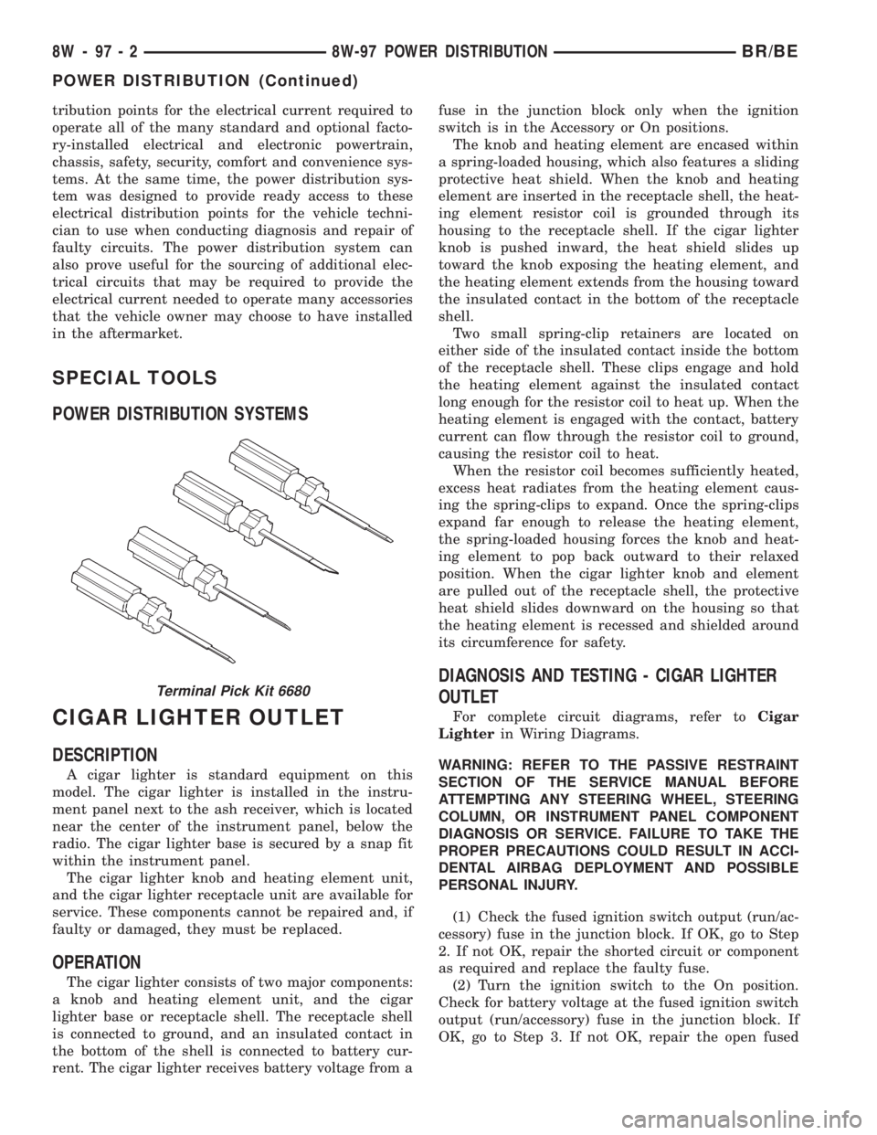
SPECIAL TOOLS
POWER DISTRIBUTION SYSTEMS
CIGAR LIGHTER OUTLET
DESCRIPTION
A cigar lighter is standard equipment on this
model. The cigar lighter is installed in the instru-
ment panel next to the ash receiver, which is located
near the center of the instrument panel, below the
radio. The cigar lighter base is secured by a snap fit
within the instrument panel.
The cigar lighter knob and heating element unit,
and the cigar lighter receptacle unit are available for
service. These components cannot be repaired and, if
faulty or damaged, they must be replaced.
OPERATION
The cigar lighter consists of two major components:
a knob and heating element unit, and the cigar
lighter base or receptacle shell. The receptacle shell
is connected to ground, and an insulated contact in
the bottom of the shell is connected to battery cur-
rent. The cigar lighter receives battery voltage from afuse in the junction block only when the ignition
switch is in the Accessory or On positions.
The knob and heating element are encased within
a spring-loaded housing, which also features a sliding
protective heat shield. When the knob and heating
element are inserted in the receptacle shell, the heat-
ing element resistor coil is grounded through its
housing to the receptacle shell. If the cigar lighter
knob is pushed inward, the heat shield slides up
toward the knob exposing the heating element, and
the heating element extends from the housing toward
the insulated contact in the bottom of the receptacle
shell.
Two small spring-clip retainers are located on
either side of the insulated contact inside the bottom
of the receptacle shell. These clips engage and hold
the heating element against the insulated contact
long enough for the resistor coil to heat up. When the
heating element is engaged with the contact, battery
current can flow through the resistor coil to ground,
causing the resistor coil to heat.
When the resistor coil becomes sufficiently heated,
excess heat radiates from the heating element caus-
ing the spring-clips to expand. Once the spring-clips
expand far enough to release the heating element,
the spring-loaded housing forces the knob and heat-
ing element to pop back outward to their relaxed
position. When the cigar lighter knob and element
are pulled out of the receptacle shell, the protective
heat shield slides downward on the housing so that
the heating element is recessed and shielded around
its circumference for safety.
DIAGNOSIS AND TESTING - CIGAR LIGHTER
OUTLET
For complete circuit diagrams, refer toCigar
Lighterin Wiring Diagrams.
WARNING: REFER TO THE PASSIVE RESTRAINT
SECTION OF THE SERVICE MANUAL BEFORE
ATTEMPTING ANY STEERING WHEEL, STEERING
COLUMN, OR INSTRUMENT PANEL COMPONENT
DIAGNOSIS OR SERVICE. FAILURE TO TAKE THE
PROPER PRECAUTIONS COULD RESULT IN ACCI-
DENTAL AIRBAG DEPLOYMENT AND POSSIBLE
PERSONAL INJURY.
(1) Check the fused ignition switch output (run/ac-
cessory) fuse in the junction block. If OK, go to Step
2. If not OK, repair the shorted circuit or component
as required and replace the faulty fuse.
(2) Turn the ignition switch to the On position.
Check for battery voltage at the fused ignition switch
output (run/accessory) fuse in the junction block. If
OK, go to Step 3. If not OK, repair the open fused
Terminal Pick Kit 6680
8W - 97 - 2 8W-97 POWER DISTRIBUTIONBR/BE
POWER DISTRIBUTION (Continued)
Page 1063 of 2255
(8) Remove the cigar lighter or power outlet mount
from the instrument panel.
INSTALLATION
(1) Reconnect the instrument panel wire harness
connector to the cigar lighter or power outlet recep-
tacle base connector receptacle.
(2) Install the cigar lighter or power outlet mount
into the instrument panel.
(3) Align the splines on the outside of the cigar
lighter or power outlet receptacle base connector
receptacle with the grooves on the inside of the
mount.
(4) Press firmly on the cigar lighter or power out-
let receptacle base until the retaining bosses of the
mount are fully engaged in their receptacles.
(5) Install the cigar lighter knob and element into
the cigar lighter receptacle base, or the protective cap
into the power outlet receptacle base.
(6) Reconnect the battery negative cable.
CIRCUIT BREAKER
DESCRIPTION
Automatic resetting circuit breakers are used to
protect a system circuit from a short circuit or over-
load. Some examples of his condition can be caused
by an obstructed or stuck seat adjuster or power win-
dow motor.
The circuit breaker cannot be repaired and, if
faulty or damaged, it must be replaced.
DIAGNOSIS AND TESTING - CIRCUIT BREAKER
For circuit descriptions and diagrams, refer to Wir-
ing Diagrams.
(1) Locate the correct circuit breaker in the junc-
tion block. Pull out the circuit breaker slightly, but
be certain that the circuit breaker terminals still con-
tact the terminals in the junction block cavities.
(2) Connect the negative lead of a 12-volt DC volt-
meter to a good ground.
(3) With the voltmeter positive lead, check both
terminals of the circuit breaker for battery voltage.
If only one terminal has battery voltage, the circuit
breaker is faulty and must be replaced. If neither ter-
minal has battery voltage, repair the open circuit
from the Power Distribution Center (PDC) as
required.
GENERATOR CARTRIDGE
FUSE
DESCRIPTION
A 140 ampere generator cartridge fuse is used on
this model. The generator cartridge fuse is similar to
other cartridge fuses found in the Power Distribution
Center (PDC). This fuse has a color-coded plastic
housing and a clear plastic fuse conductor inspection
cover like other cartridge fuses, but has a higher cur-
rent rating and is connected and secured with screws
instead of being pushed onto male spade-type termi-
nals. The generator cartridge fuse cannot be repaired
and, if faulty or damaged, it must be replaced.
OPERATION
The generator cartridge fuse is secured between
the two B(+) terminal stud connection bus bars
within the Power Distribution Center (PDC). This
fuse protects the vehicle electrical system from dam-
age that could be caused by excessive charging sys-
tem output and/or excessive electrical system current
levels resulting from a faulty generator or faulty
charging system control circuits. If the current rating
of the fuse is exceeded, the fuse conductor melts to
open the generator output circuit connection to the
PDC. If a generator cartridge fuse fails, be certain to
completely inspect and test the vehicle charging sys-
tem before replacing the fuse and returning the vehi-
cle to service. Refer toCharging Systemfor the
charging system diagnostic procedures. Refer toWir-
ing Diagramsfor the location of complete PDC cir-
cuit diagrams.
REMOVAL
If a generator cartridge fuse fails, be certain to
inspect and test the vehicle charging system before
replacing the cartridge fuse and returning the vehicle
to service. Refer toCharging Systemin the index of
this service manual for the charging system diagnos-
tic procedures.
(1) Disconnect and isolate the battery negative
cable.
(2) Unlatch and remove the cover from the Power
Distribution Center (PDC).
(3) Remove the two screws that secure the genera-
tor cartridge fuse to the two B(+) terminal stud bus
bars within the PDC.
(4) Remove the generator cartridge fuse from the
PDC.
INSTALLATION
If a generator cartridge fuse fails, be certain to
inspect and test the vehicle charging system before
replacing the cartridge fuse and returning the vehicle
8W - 97 - 4 8W-97 POWER DISTRIBUTIONBR/BE
CIGAR LIGHTER OUTLET (Continued)
Page 1064 of 2255
to service. Refer toCharging Systemin the index of
this service manual for the charging system diagnos-
tic procedures.
(1) Position the generator cartridge fuse onto the
two B(+) terminal stud bus bars within the PDC.
(2) Install and tighten the two screws that secure
the generator cartridge fuse to the two B(+) terminal
stud bus bars within the PDC. Tighten the screws to
3.4 N´m (30 in. lbs.).Be certain that both screws
are tightened to the proper torque value.
(3) Install and latch the cover onto the PDC.
(4) Reconnect the battery negative cable.
IOD FUSE
DESCRIPTION
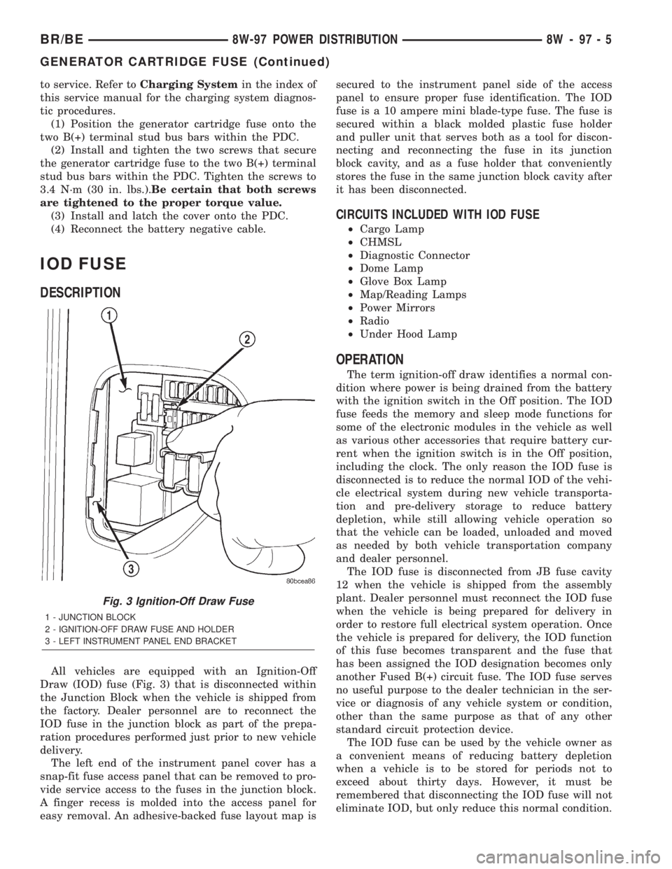
All vehicles are equipped with an Ignition-Off
Draw (IOD) fuse (Fig. 3) that is disconnected within
the Junction Block when the vehicle is shipped from
the factory. Dealer personnel are to reconnect the
IOD fuse in the junction block as part of the prepa-
ration procedures performed just prior to new vehicle
delivery.
The left end of the instrument panel cover has a
snap-fit fuse access panel that can be removed to pro-
vide service access to the fuses in the junction block.
A finger recess is molded into the access panel for
easy removal. An adhesive-backed fuse layout map issecured to the instrument panel side of the access
panel to ensure proper fuse identification. The IOD
fuse is a 10 ampere mini blade-type fuse. The fuse is
secured within a black molded plastic fuse holder
and puller unit that serves both as a tool for discon-
necting and reconnecting the fuse in its junction
block cavity, and as a fuse holder that conveniently
stores the fuse in the same junction block cavity after
it has been disconnected.
CIRCUITS INCLUDED WITH IOD FUSE
²Cargo Lamp
²CHMSL
²Diagnostic Connector
²Dome Lamp
²Glove Box Lamp
²Map/Reading Lamps
²Power Mirrors
²Radio
²Under Hood Lamp
OPERATION
The term ignition-off draw identifies a normal con-
dition where power is being drained from the battery
with the ignition switch in the Off position. The IOD
fuse feeds the memory and sleep mode functions for
some of the electronic modules in the vehicle as well
as various other accessories that require battery cur-
rent when the ignition switch is in the Off position,
including the clock. The only reason the IOD fuse is
disconnected is to reduce the normal IOD of the vehi-
cle electrical system during new vehicle transporta-
tion and pre-delivery storage to reduce battery
depletion, while still allowing vehicle operation so
that the vehicle can be loaded, unloaded and moved
as needed by both vehicle transportation company
and dealer personnel.
The IOD fuse is disconnected from JB fuse cavity
12 when the vehicle is shipped from the assembly
plant. Dealer personnel must reconnect the IOD fuse
when the vehicle is being prepared for delivery in
order to restore full electrical system operation. Once
the vehicle is prepared for delivery, the IOD function
of this fuse becomes transparent and the fuse that
has been assigned the IOD designation becomes only
another Fused B(+) circuit fuse. The IOD fuse serves
no useful purpose to the dealer technician in the ser-
vice or diagnosis of any vehicle system or condition,
other than the same purpose as that of any other
standard circuit protection device.
The IOD fuse can be used by the vehicle owner as
a convenient means of reducing battery depletion
when a vehicle is to be stored for periods not to
exceed about thirty days. However, it must be
remembered that disconnecting the IOD fuse will not
eliminate IOD, but only reduce this normal condition.
Fig. 3 Ignition-Off Draw Fuse
1 - JUNCTION BLOCK
2 - IGNITION-OFF DRAW FUSE AND HOLDER
3 - LEFT INSTRUMENT PANEL END BRACKET
BR/BE8W-97 POWER DISTRIBUTION 8W - 97 - 5
GENERATOR CARTRIDGE FUSE (Continued)
Page 1198 of 2255
(1) Disconnect the negative cable(s) from the bat-
tery.
(2) Inspect air cleaner, induction system, and
intake manifold to ensure system is dry and clear of
foreign material.
(3) Place a shop towel around the fuel injectors to
catch any fluid that may possibly be under pressure
in the cylinder head. Remove the fuel injectors (Refer
to 14 - FUEL SYSTEM/FUEL INJECTION/FUEL
INJECTOR - REMOVAL).
(4) With all injectors removed, rotate the crank-
shaft using a breaker bar and socket.
(5) Identify the fluid in the cylinders (coolant, fuel,
oil, etc.).
(6) Be sure all fluid has been removed from the
cylinders.
(7) Repair engine or components as necessary to
prevent this problem from occurring again.
(8) Squirt a small amount of engine oil into the
cylinders to lubricate the walls. This will prevent
damage on restart.
(9) Install new fuel injectors (Refer to 14 - FUEL
SYSTEM/FUEL INJECTION/FUEL INJECTOR -
INSTALLATION).
(10) Drain engine oil. Remove and discard the oil
filter (Refer to 9 - ENGINE/LUBRICATION/OIL FIL-
TER - REMOVAL).
(11) Install the drain plug. Tighten the plug to 34
N´m (25 ft. lbs.) torque.
(12) Install a new oil filter (Refer to 9 - ENGINE/
LUBRICATION/OIL FILTER - INSTALLATION).
(13) Fill engine crankcase with the specified
amount and grade of oil (Refer to LUBRICATION &
MAINTENANCE/FLUID TYPES - SPECIFICA-
TIONS).
(14) Connect the negative cable(s) to the battery.
(15) Start the engine and check for any leaks.
REMOVAL
REMOVALÐENGINE
(1) Disconnect both battery negative cables.
(2) Recover A/C refrigerant (if A/C equipped) (Refer
to 24 - HEATING & AIR CONDITIONING/PLUMB-
ING - STANDARD PROCEDURE).
(3) Raise vehicle on hoist.
(4) Drain engine coolant (Refer to 7 - COOLING -
STANDARD PROCEDURE).
(5) Remove engine oil drain plug and drain engine
oil.
(6) Lower vehicle.
(7) Remove radiator upper hose.
(8) Remove the cooling fan shroud-to-radiator
mounting bolts.(9) Remove viscous fan/drive assembly (Refer to 7 -
COOLING/ENGINE/RADIATOR FAN - REMOVAL).
Remove the cooling fan and shroud together.
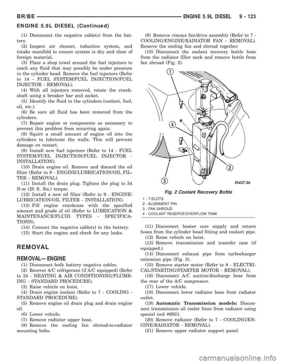
(10) Disconnect the coolant recovery bottle hose
from the radiator filler neck and remove bottle from
fan shroud (Fig. 2).
(11) Disconnect heater core supply and return
hoses from the cylinder head fitting and coolant pipe.
(12) Raise vehicle on hoist.
(13) Remove transmission and transfer case (if
equipped.).
(14) Disconnect exhaust pipe from turbocharger
extension pipe (Fig. 3).
(15) Remove starter motor (Refer to 8 - ELECTRI-
CAL/STARTING/STARTER MOTOR - REMOVAL).
(16) Disconnect A/C suction/discharge hose from
the rear of the A/C compressor.
(17) Lower vehicle.
(18) Disconnect lower radiator hose from radiator
outlet.
(19)Automatic Transmission models:Discon-
nect transmission oil cooler lines from radiator using
special tool #6931.
(20) Remove radiator (Refer to 7 - COOLING/EN-
GINE/RADIATOR - REMOVAL).
(21) Remove upper radiator support panel.
Fig. 2 Coolant Recovery Bottle
1 - T-SLOTS
2 - ALIGNMENT PIN
3 - FAN SHROUD
4 - COOLANT RESERVE/OVERFLOW TANK
BR/BEENGINE 5.9L DIESEL 9 - 123
ENGINE 5.9L DIESEL (Continued)
Page 1228 of 2255
(5) Lower vehicle.
(6) Remove radiator upper hose.
(7) Remove viscous fan/drive assembly and fan
shroud (Refer to 7 - COOLING/ENGINE/RADIATOR
FAN - REMOVAL).
(8) Disconnect the coolant recovery bottle hose
from the radiator filler neck.
(9) Disconnect lower radiator hose from radiator
outlet.
(10)Automatic Transmission models:Discon-
nect transmission oil cooler lines from radiator using
Special Tool 6931 (unless equipped with finger-re-
lease disconnect).
(11) Remove radiator mounting screws and lift
radiator out of engine compartment.
(12) Remove upper radiator support panel.
(13) Remove front bumper assembly (Refer to 13 -
FRAMES & BUMPERS/BUMPERS/FRONT
BUMPER - REMOVAL).
(14) If A/C equipped, disconnect A/C condenser
refrigerant lines.
(15) Disconnect charge air cooler piping from the
cooler inlet and outlet.
(16) Remove the two charge air cooler mounting
bolts.
(17) Remove charge air cooler (and A/C condenser
if equipped) from vehicle.
(18) Remove accessory drive belt (Refer to 7 -
COOLING/ACCESSORY DRIVE/DRIVE BELTS -
REMOVAL).
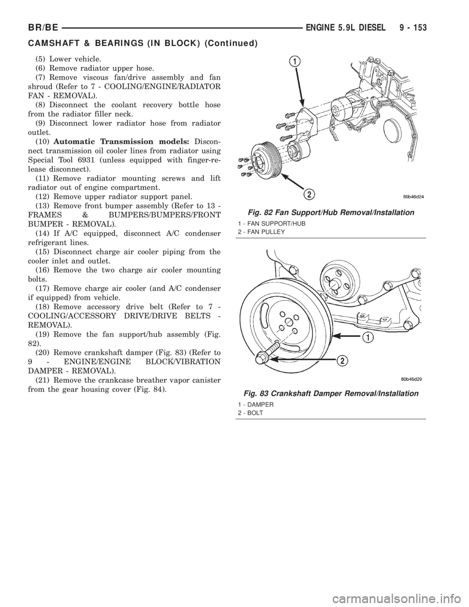
(19) Remove the fan support/hub assembly (Fig.
82).
(20) Remove crankshaft damper (Fig. 83) (Refer to
9 - ENGINE/ENGINE BLOCK/VIBRATION
DAMPER - REMOVAL).
(21) Remove the crankcase breather vapor canister
from the gear housing cover (Fig. 84).
Fig. 82 Fan Support/Hub Removal/Installation
1 - FAN SUPPORT/HUB
2 - FAN PULLEY
Fig. 83 Crankshaft Damper Removal/Installation
1 - DAMPER
2 - BOLT
BR/BEENGINE 5.9L DIESEL 9 - 153
CAMSHAFT & BEARINGS (IN BLOCK) (Continued)
Page 1281 of 2255
(4) Connect the DRBIIItto the pressure trans-
ducer following the instructions supplied with the
DRB IIIt.
(5) Enter DRBIIItinto pressure reading mode and
test drive vehicle.
(6) The turbocharger boost pressure must be
between 110 - 138 kpa (16 - 20 psi.). If pressure read-
ings are lower than 110 kpa (16 psi.) inspect for the
following:
²Restricted air inlet system
²Leak in the charge air cooler system (Refer to 11
- EXHAUST SYSTEM/TURBOCHARGER SYSTEM/
CHARGE AIR COOLER AND PLUMBING - DIAG-
NOSIS AND TESTING)
²Turbocharger wastegate broken or misadjusted
²Turbocharger damaged (Refer to 11 - EXHAUST
SYSTEM/TURBOCHARGER SYSTEM/TURBO-
CHARGER - INSPECTION)
TURBOCHARGER
DESCRIPTION
The turbocharger is an exhaust-driven super-
charger which increases the pressure and density of
the air entering the engine. With the increase of air
entering the engine, more fuel can be injected into
the cylinders, which creates more power during com-
bustion.
The turbocharger assembly consists of four (4)
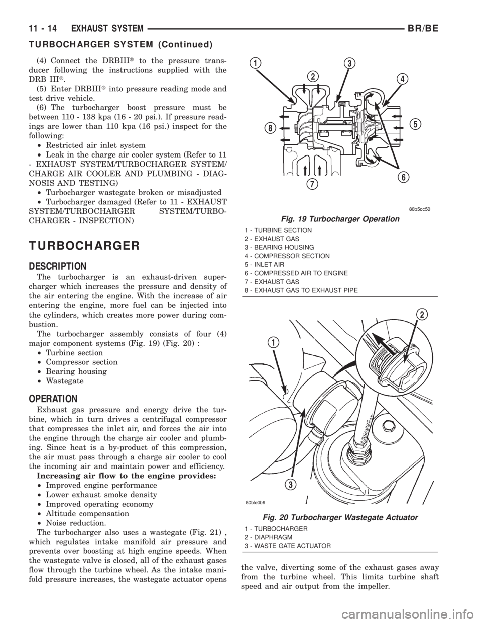
major component systems (Fig. 19) (Fig. 20) :
²Turbine section
²Compressor section
²Bearing housing
²Wastegate
OPERATION
Exhaust gas pressure and energy drive the tur-
bine, which in turn drives a centrifugal compressor
that compresses the inlet air, and forces the air into
the engine through the charge air cooler and plumb-
ing. Since heat is a by-product of this compression,
the air must pass through a charge air cooler to cool
the incoming air and maintain power and efficiency.
Increasing air flow to the engine provides:
²Improved engine performance
²Lower exhaust smoke density
²Improved operating economy
²Altitude compensation
²Noise reduction.
The turbocharger also uses a wastegate (Fig. 21) ,
which regulates intake manifold air pressure and
prevents over boosting at high engine speeds. When
the wastegate valve is closed, all of the exhaust gases
flow through the turbine wheel. As the intake mani-
fold pressure increases, the wastegate actuator opensthe valve, diverting some of the exhaust gases away
from the turbine wheel. This limits turbine shaft
speed and air output from the impeller.
Fig. 19 Turbocharger Operation
1 - TURBINE SECTION
2 - EXHAUST GAS
3 - BEARING HOUSING
4 - COMPRESSOR SECTION
5 - INLET AIR
6 - COMPRESSED AIR TO ENGINE
7 - EXHAUST GAS
8 - EXHAUST GAS TO EXHAUST PIPE
Fig. 20 Turbocharger Wastegate Actuator
1 - TURBOCHARGER
2 - DIAPHRAGM
3 - WASTE GATE ACTUATOR
11 - 14 EXHAUST SYSTEMBR/BE
TURBOCHARGER SYSTEM (Continued)