2002 DODGE RAM relay
[x] Cancel search: relayPage 456 of 2255

the horn switch is damaged or faulty, or if the driver
side airbag is deployed, the driver side airbag module
trim cover and horn switch must be replaced as a
unit.
OPERATION
When the center area of the driver side airbag trim
cover is depressed, the electrically conductive grids
on the facing surfaces of the horn switch membranes
contact each other, closing the switch circuit. The
completed horn switch circuit provides a ground for
the control coil side of the horn relay, which activates
the relay. When the horn switch is released, the
resistive tension of the convex membrane separates
the two electrically conductive grids and opens the
switch circuit.
DIAGNOSIS AND TESTING - HORN SWITCH
For complete circuit diagrams, refer to the appro-
priate wiring information. The wiring information
includes wiring diagrams, proper wire and connector
repair procedures, details of wire harness routing
and retention, connector pin-out information and
location views for the various wire harness connec-
tors, splices and grounds.
WARNING: ON VEHICLES EQUIPPED WITH AIR-
BAGS, REFER TO ELECTRICAL, RESTRAINTSBEFORE ATTEMPTING ANY STEERING WHEEL,
STEERING COLUMN, OR INSTRUMENT PANEL
COMPONENT DIAGNOSIS OR SERVICE. FAILURE
TO TAKE THE PROPER PRECAUTIONS COULD
RESULT IN ACCIDENTAL AIRBAG DEPLOYMENT
AND POSSIBLE PERSONAL INJURY.
(1) Disconnect and isolate the battery negative
cable. Remove the steering column opening cover
from the instrument panel.
(2) Check for continuity between the metal steer-
ing column jacket and a good ground. There should
be continuity. If OK, go to Step 3. If not OK,(Refer to
19 - STEERING/COLUMN - INSTALLATION) for
proper installation of the steering column.
(3) Remove the driver side airbag module from the
steering wheel. Disconnect the horn switch wire har-
ness connectors from the driver side airbag module.
(4) Remove the horn relay from the Power Distri-
bution Center (PDC). Check for continuity between
the steering column half of the horn switch feed wire
harness connector and a good ground. There should
be no continuity. If OK, go to Step 5. If not OK,
repair the shorted horn relay control circuit to the
horn relay in the PDC as required.
(5) Check for continuity between the steering col-
umn half of the horn switch feed wire harness con-
nector and the horn relay control circuit cavity for
the horn relay in the PDC. There should be continu-
ity. If OK, go to Step 6. If not OK, repair the open
horn relay control circuit to the horn relay in the
PDC as required.
(6) Check for continuity between the horn switch
feed wire and the horn switch ground wire on the
driver side airbag module. There should be no conti-
nuity. If OK, go to Step 7. If not OK, replace the
faulty horn switch.
(7) Depress the center of the driver side airbag
module trim cover and check for continuity between
the horn switch feed wire and the horn switch
ground wire on the driver side airbag module. There
should now be continuity. If not OK, replace the
faulty horn switch.REMOVAL
If the horn switch is damaged or faulty, or if the
driver side airbag is deployed, the driver side airbag
module trim cover and horn switch must be replaced
as a unit. (Refer to 8 - ELECTRICAL/RESTRAINTS/
DRIVER AIRBAG - REMOVAL).
Fig. 4 Driver Side Airbag Module Trim Cover and
Horn Switch
1 - RETAINER SLOTS
2 - LOCKING BLOCKS
3 - RETAINER SLOTS
4 - HORN SWITCH
BR/BEHORN 8H - 5
HORN SWITCH (Continued)
Page 458 of 2255

IGNITION CONTROL
TABLE OF CONTENTS
page page
IGNITION CONTROL
DESCRIPTION - 8.0L V-10.................2
OPERATION
OPERATION - 8.0L V-10.................2
OPERATION - V-8......................2
SPECIFICATIONS
SPECIFICATIONS - TORQUE - IGNITION....2
SPARK PLUG CABLE ORDERÐ8.0L V-10
ENGINE..............................3
ENGINE FIRING ORDERÐ5.9L V-8
ENGINES............................3
SPARK PLUG CABLE RESISTANCE........3
SPARK PLUGS........................3
IGNITION COIL RESISTANCEÐ5.9L
ENGINES............................3
IGNITION COIL RESISTANCEÐ8.0L V-10
ENGINE..............................4
IGNITION TIMING......................4
AUTOMATIC SHUT DOWN RELAY
DESCRIPTION - PCM OUTPUT.............4
OPERATION
OPERATION - PCM OUTPUT.............4
OPERATION - ASD SENSE - PCM INPUT....4
DIAGNOSIS AND TESTING - ASD AND FUEL
PUMP RELAYS........................4
REMOVAL.............................5
INSTALLATION..........................5
CAMSHAFT POSITION SENSOR
DESCRIPTION
DESCRIPTION - DIESEL.................6
DESCRIPTION - 5.9L....................6
DESCRIPTION - 8.0L....................6
OPERATION
OPERATION - DIESEL...................6
OPERATION - 5.9L.....................7
OPERATION - 8.0L.....................7
REMOVAL
REMOVAL - DIESEL....................7
REMOVAL - 5.9L.......................7
REMOVAL - 8.0L.......................8
INSTALLATION
INSTALLATION - DIESEL.................9INSTALLATION - 5.9L..................10
INSTALLATION - 8.0L..................10
DISTRIBUTOR
DESCRIPTION.........................11
OPERATION...........................12
REMOVAL.............................12
INSTALLATION.........................13
DISTRIBUTOR CAP
DIAGNOSIS AND TESTING - DISTRIBUTOR
CAP ................................14
DISTRIBUTOR ROTOR
DIAGNOSIS AND TESTING - DISTRIBUTOR
ROTOR .............................14
IGNITION COIL
DESCRIPTION
DESCRIPTION - 5.9L...................15
DESCRIPTION - 8.0L...................15
OPERATION
OPERATION - 5.9L....................15
OPERATION - 8.0L....................15
REMOVAL
REMOVAL - 5.9L......................15
REMOVAL - 8.0L......................16
INSTALLATION
INSTALLATION - 5.9L..................16
INSTALLATION - 8.0L..................16
SPARK PLUG
DESCRIPTION.........................16
OPERATION...........................16
DIAGNOSIS AND TESTING - SPARK PLUG
CONDITIONS.........................17
REMOVAL.............................19
CLEANING............................20
INSTALLATION.........................20
SPARK PLUG CABLE
DESCRIPTION.........................20
OPERATION...........................20
DIAGNOSIS AND TESTING - SPARK PLUG
CABLES............................20
REMOVAL.............................21
INSTALLATION.........................21
BR/BEIGNITION CONTROL 8I - 1
Page 461 of 2255

IGNITION COIL RESISTANCEÐ8.0L V-10
ENGINE
Primary Resistance: 0.53-0.65 Ohms. Test across the
primary connector. Refer to text for test procedures.
Secondary Resistance: 10.9-14.7K Ohms. Test
across the individual coil towers. Refer to text for test
procedures.
IGNITION TIMING
Ignition timing is not adjustable on any engine.
AUTOMATIC SHUT DOWN
RELAY
DESCRIPTION - PCM OUTPUT
The 5±pin, 12±volt, Automatic Shutdown (ASD)
relay is located in the Power Distribution Center
(PDC). Refer to label on PDC cover for relay location.
OPERATION
OPERATION - PCM OUTPUT
The ASD relay supplies battery voltage (12+ volts)
to the fuel injectors and ignition coil(s). With certain
emissions packages it also supplies 12±volts to the
oxygen sensor heating elements.
The ground circuit for the coil within the ASD
relay is controlled by the Powertrain Control Module
(PCM). The PCM operates the ASD relay by switch-
ing its ground circuit on and off.
The ASD relay will be shut±down, meaning the
12±volt power supply to the ASD relay will be de-ac-
tivated by the PCM if:
²the ignition key is left in the ON position. This
is if the engine has not been running for approxi-
mately 1.8 seconds.
²there is a crankshaft position sensor signal to
the PCM that is lower than pre-determined values.
OPERATION - ASD SENSE - PCM INPUT
A 12 volt signal at this input indicates to the PCM
that the ASD has been activated. The relay is used to
connect the oxygen sensor heater element, ignition
coil and fuel injectors to 12 volt + power supply.
This input is used only to sense that the ASD relay
is energized. If the Powertrain Control Module
(PCM) does not see 12 volts at this input when the
ASD should be activated, it will set a Diagnostic
Trouble Code (DTC).
DIAGNOSIS AND TESTING - ASD AND FUEL
PUMP RELAYS
The following description of operation and
tests apply only to the Automatic Shutdown
(ASD) and fuel pump relays. The terminals on the
bottom of each relay are numbered. Two different
types of relays may be used, (Fig. 1) or (Fig. 2).
Fig. 1 ASD and Fuel Pump Relay TerminalsÐType 1
TERMINAL LEGEND
NUMBER IDENTIFICATION
30 COMMON FEED
85 COIL GROUND
86 COIL BATTERY
87 NORMALLY OPEN
87A NORMALLY CLOSED
Fig. 2 ASD and Fuel Pump Relay TerminalsÐType 2
TERMINAL LEGEND
NUMBER IDENTIFICATION
30 COMMON FEED
85 COIL GROUND
86 COIL BATTERY
87 NORMALLY OPEN
87A NORMALLY CLOSED
8I - 4 IGNITION CONTROLBR/BE
IGNITION CONTROL (Continued)
Page 462 of 2255
²Terminal number 30 is connected to battery volt-
age. For both the ASD and fuel pump relays, termi-
nal 30 is connected to battery voltage at all times.
²The PCM grounds the coil side of the relay
through terminal number 85.
²Terminal number 86 supplies voltage to the coil
side of the relay.
²When the PCM de-energizes the ASD and fuel
pump relays, terminal number 87A connects to termi-
nal 30. This is the Off position. In the off position,
voltage is not supplied to the rest of the circuit. Ter-
minal 87A is the center terminal on the relay.
²When the PCM energizes the ASD and fuel
pump relays, terminal 87 connects to terminal 30.
This is the On position. Terminal 87 supplies voltage
to the rest of the circuit.
The following procedure applies to the ASD and
fuel pump relays.
(1) Remove relay from connector before testing.
(2) With the relay removed from the vehicle, use
an ohmmeter to check the resistance between termi-
nals 85 and 86. The resistance should be 75 ohms +/-
5 ohms.
(3) Connect the ohmmeter between terminals 30
and 87A. The ohmmeter should show continuity
between terminals 30 and 87A.
(4) Connect the ohmmeter between terminals 87
and 30. The ohmmeter should not show continuity at
this time.
(5) Connect one end of a jumper wire (16 gauge or
smaller) to relay terminal 85. Connect the other end
of the jumper wire to the ground side of a 12 volt
power source.
(6) Connect one end of another jumper wire (16
gauge or smaller) to the power side of the 12 volt
power source.Do not attach the other end of the
jumper wire to the relay at this time.
WARNING: DO NOT ALLOW OHMMETER TO CON-
TACT TERMINALS 85 OR 86 DURING THIS TEST.
DAMAGE TO OHMMETER MAY RESULT.
(7) Attach the other end of the jumper wire to
relay terminal 86. This activates the relay. The ohm-
meter should now show continuity between relay ter-
minals 87 and 30. The ohmmeter should not show
continuity between relay terminals 87A and 30.
(8) Disconnect jumper wires.(9) Replace the relay if it did not pass the continu-
ity and resistance tests. If the relay passed the tests,
it operates properly. Check the remainder of the ASD
and fuel pump relay circuits. Refer to 8, Wiring Dia-
grams.
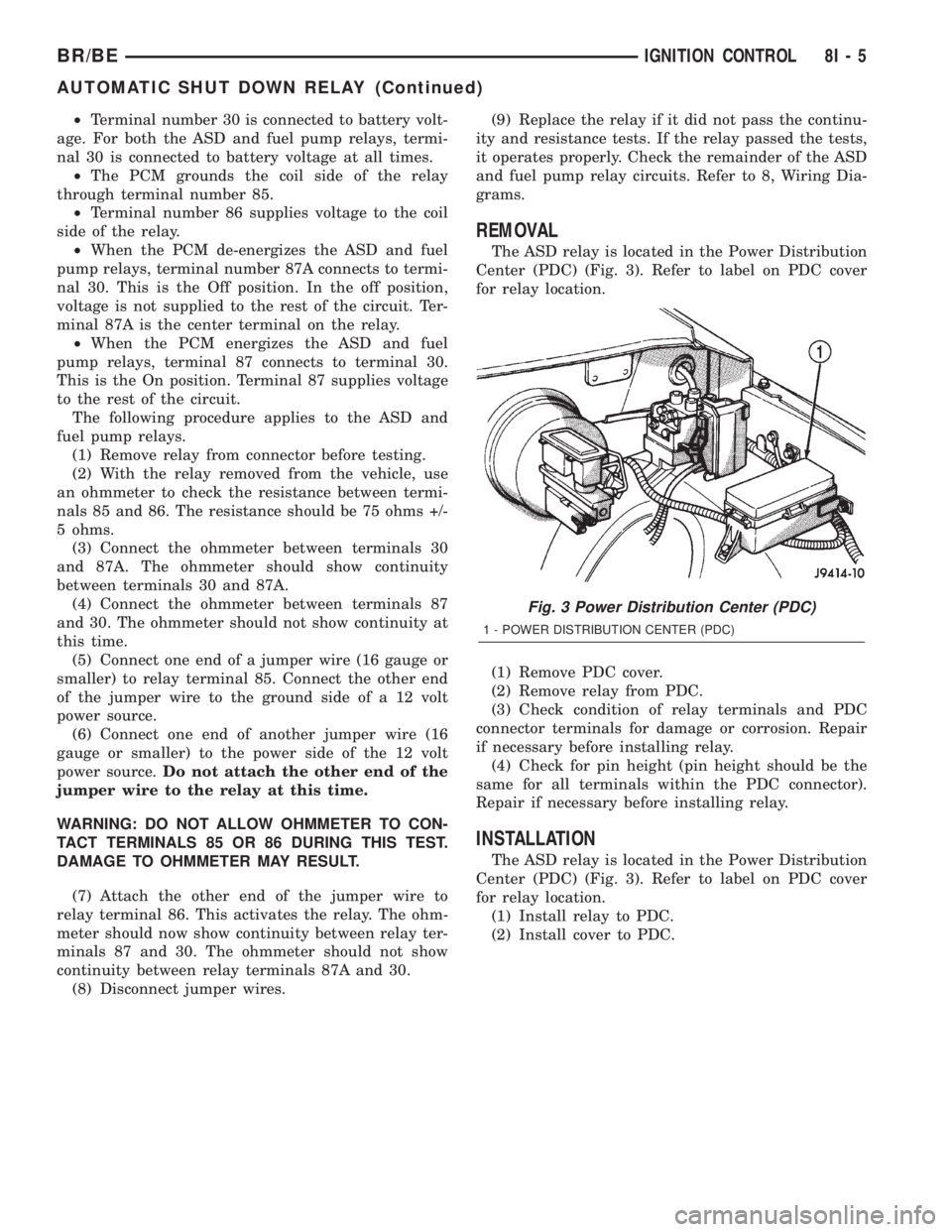
REMOVAL
The ASD relay is located in the Power Distribution
Center (PDC) (Fig. 3). Refer to label on PDC cover
for relay location.
(1) Remove PDC cover.
(2) Remove relay from PDC.
(3) Check condition of relay terminals and PDC
connector terminals for damage or corrosion. Repair
if necessary before installing relay.
(4) Check for pin height (pin height should be the
same for all terminals within the PDC connector).
Repair if necessary before installing relay.
INSTALLATION
The ASD relay is located in the Power Distribution
Center (PDC) (Fig. 3). Refer to label on PDC cover
for relay location.
(1) Install relay to PDC.
(2) Install cover to PDC.
Fig. 3 Power Distribution Center (PDC)
1 - POWER DISTRIBUTION CENTER (PDC)
BR/BEIGNITION CONTROL 8I - 5
AUTOMATIC SHUT DOWN RELAY (Continued)
Page 472 of 2255
IGNITION COIL
DESCRIPTION
DESCRIPTION - 5.9L
A single ignition coil is used. The coil is not oil
filled. The coil windings are embedded in an epoxy
compound. This provides heat and vibration resis-
tance that allows the coil to be mounted on the
engine.
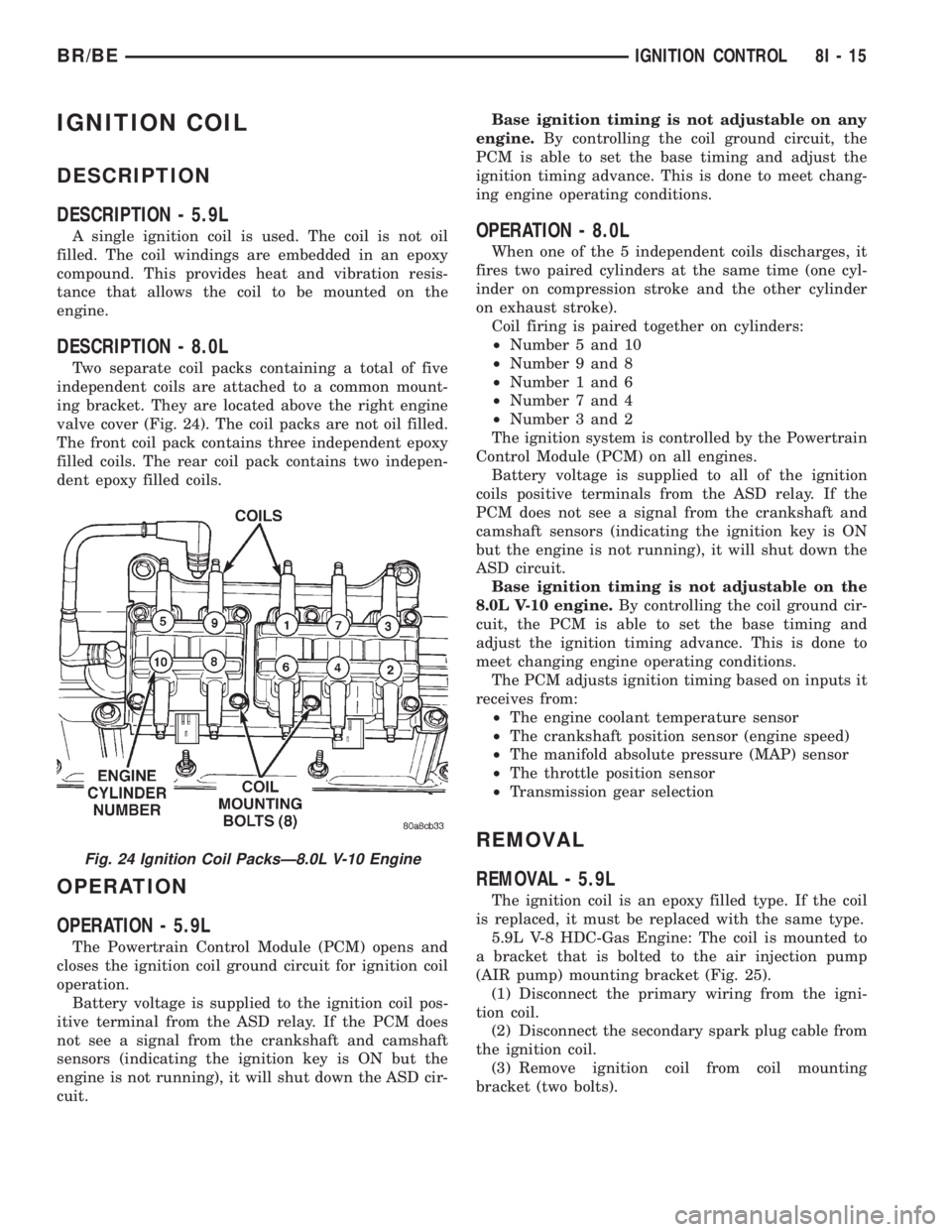
DESCRIPTION - 8.0L
Two separate coil packs containing a total of five
independent coils are attached to a common mount-
ing bracket. They are located above the right engine
valve cover (Fig. 24). The coil packs are not oil filled.
The front coil pack contains three independent epoxy
filled coils. The rear coil pack contains two indepen-
dent epoxy filled coils.
OPERATION
OPERATION - 5.9L
The Powertrain Control Module (PCM) opens and
closes the ignition coil ground circuit for ignition coil
operation.
Battery voltage is supplied to the ignition coil pos-
itive terminal from the ASD relay. If the PCM does
not see a signal from the crankshaft and camshaft
sensors (indicating the ignition key is ON but the
engine is not running), it will shut down the ASD cir-
cuit.Base ignition timing is not adjustable on any
engine.By controlling the coil ground circuit, the
PCM is able to set the base timing and adjust the
ignition timing advance. This is done to meet chang-
ing engine operating conditions.
OPERATION - 8.0L
When one of the 5 independent coils discharges, it
fires two paired cylinders at the same time (one cyl-
inder on compression stroke and the other cylinder
on exhaust stroke).
Coil firing is paired together on cylinders:
²Number 5 and 10
²Number 9 and 8
²Number 1 and 6
²Number 7 and 4
²Number 3 and 2
The ignition system is controlled by the Powertrain
Control Module (PCM) on all engines.
Battery voltage is supplied to all of the ignition
coils positive terminals from the ASD relay. If the
PCM does not see a signal from the crankshaft and
camshaft sensors (indicating the ignition key is ON
but the engine is not running), it will shut down the
ASD circuit.
Base ignition timing is not adjustable on the
8.0L V-10 engine.By controlling the coil ground cir-
cuit, the PCM is able to set the base timing and
adjust the ignition timing advance. This is done to
meet changing engine operating conditions.
The PCM adjusts ignition timing based on inputs it
receives from:
²The engine coolant temperature sensor
²The crankshaft position sensor (engine speed)
²The manifold absolute pressure (MAP) sensor
²The throttle position sensor
²Transmission gear selection
REMOVAL
REMOVAL - 5.9L
The ignition coil is an epoxy filled type. If the coil
is replaced, it must be replaced with the same type.
5.9L V-8 HDC-Gas Engine: The coil is mounted to
a bracket that is bolted to the air injection pump
(AIR pump) mounting bracket (Fig. 25).
(1) Disconnect the primary wiring from the igni-
tion coil.
(2) Disconnect the secondary spark plug cable from
the ignition coil.
(3) Remove ignition coil from coil mounting
bracket (two bolts).
Fig. 24 Ignition Coil PacksÐ8.0L V-10 Engine
BR/BEIGNITION CONTROL 8I - 15
Page 516 of 2255
LAMPS
TABLE OF CONTENTS
page page
LAMPS/LIGHTING - EXTERIOR............... 1LAMPS/LIGHTING - INTERIOR............... 33
LAMPS/LIGHTING - EXTERIOR
TABLE OF CONTENTS
page page
LAMPS/LIGHTING - EXTERIOR
DESCRIPTION - TURN SIGNAL & HAZARD
WARNING SYSTEM.....................2
OPERATION - TURN SIGNAL & HAZARD
WARNING SYSTEM.....................2
DIAGNOSIS AND TESTING - TURN SIGNAL &
HAZARD WARNING SYSTEM.............3
SPECIFICATIONS
EXTERIOR LAMPS.....................4
SPECIAL TOOLS
HEADLAMP ALIGNMENT................4
BRAKE LAMP SWITCH
DESCRIPTION..........................4
OPERATION............................4
DIAGNOSIS AND TESTING - BRAKE LAMP
SWITCH.............................5
REMOVAL.............................5
INSTALLATION..........................6
CENTER HIGH MOUNTED STOP LAMP
REMOVAL.............................6
INSTALLATION..........................6
CENTER HIGH MOUNTED STOP LAMP UNIT
REMOVAL.............................6
INSTALLATION..........................6
CLEARANCE LAMP
REMOVAL.............................7
INSTALLATION..........................7
COMBINATION FLASHER
DESCRIPTION..........................7
OPERATION............................7
REMOVAL.............................8
INSTALLATION..........................9
DAYTIME RUNNING LAMP MODULE
DESCRIPTION..........................9
OPERATION............................9
REMOVAL.............................9
INSTALLATION..........................9FOG LAMP
DIAGNOSIS AND TESTING - FOG LAMP.....10
REMOVAL.............................11
INSTALLATION.........................11
FOG LAMP UNIT
REMOVAL.............................12
INSTALLATION.........................12
ADJUSTMENTS........................13
HEADLAMP
DESCRIPTION.........................13
OPERATION...........................13
DIAGNOSIS AND TESTING - HEADLAMP.....14
REMOVAL.............................16
INSTALLATION.........................16
HEADLAMP RELAY
DESCRIPTION.........................17
OPERATION...........................17
DIAGNOSIS AND TESTING - HEADLAMP
RELAY..............................17
REMOVAL.............................18
INSTALLATION.........................18
HEADLAMP SWITCH
DESCRIPTION.........................18
OPERATION...........................18
DIAGNOSIS AND TESTING - HEADLAMP
SWITCH............................19
REMOVAL.............................19
INSTALLATION.........................20
HEADLAMP UNIT
REMOVAL.............................20
INSTALLATION.........................21
ADJUSTMENTS........................21
LICENSE PLATE LAMP
REMOVAL.............................22
INSTALLATION.........................22
LICENSE PLATE LAMP UNIT
REMOVAL.............................22
BR/BELAMPS 8L - 1
Page 522 of 2255
CLEARANCE LAMP
REMOVAL
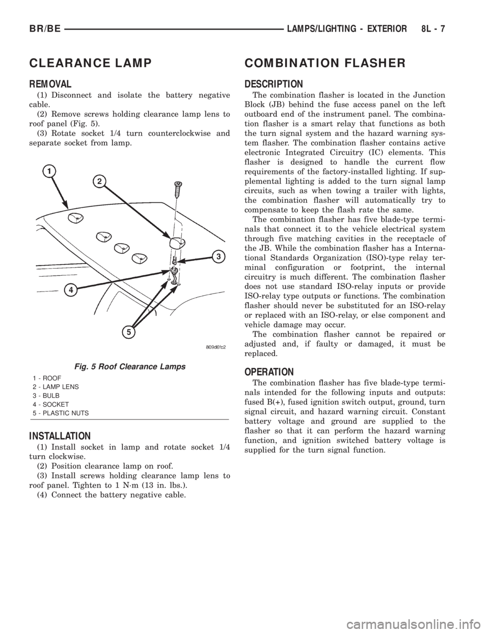
(1) Disconnect and isolate the battery negative
cable.
(2) Remove screws holding clearance lamp lens to
roof panel (Fig. 5).
(3) Rotate socket 1/4 turn counterclockwise and
separate socket from lamp.
INSTALLATION
(1) Install socket in lamp and rotate socket 1/4
turn clockwise.
(2) Position clearance lamp on roof.
(3) Install screws holding clearance lamp lens to
roof panel. Tighten to 1 N´m (13 in. lbs.).
(4) Connect the battery negative cable.
COMBINATION FLASHER
DESCRIPTION
The combination flasher is located in the Junction
Block (JB) behind the fuse access panel on the left
outboard end of the instrument panel. The combina-
tion flasher is a smart relay that functions as both
the turn signal system and the hazard warning sys-
tem flasher. The combination flasher contains active
electronic Integrated Circuitry (IC) elements. This
flasher is designed to handle the current flow
requirements of the factory-installed lighting. If sup-
plemental lighting is added to the turn signal lamp
circuits, such as when towing a trailer with lights,
the combination flasher will automatically try to
compensate to keep the flash rate the same.
The combination flasher has five blade-type termi-
nals that connect it to the vehicle electrical system
through five matching cavities in the receptacle of
the JB. While the combination flasher has a Interna-
tional Standards Organization (ISO)-type relay ter-
minal configuration or footprint, the internal
circuitry is much different. The combination flasher
does not use standard ISO-relay inputs or provide
ISO-relay type outputs or functions. The combination
flasher should never be substituted for an ISO-relay
or replaced with an ISO-relay, or else component and
vehicle damage may occur.
The combination flasher cannot be repaired or
adjusted and, if faulty or damaged, it must be
replaced.
OPERATION
The combination flasher has five blade-type termi-
nals intended for the following inputs and outputs:
fused B(+), fused ignition switch output, ground, turn
signal circuit, and hazard warning circuit. Constant
battery voltage and ground are supplied to the
flasher so that it can perform the hazard warning
function, and ignition switched battery voltage is
supplied for the turn signal function.
Fig. 5 Roof Clearance Lamps
1 - ROOF
2 - LAMP LENS
3 - BULB
4 - SOCKET
5 - PLASTIC NUTS
BR/BELAMPS/LIGHTING - EXTERIOR 8L - 7
Page 530 of 2255
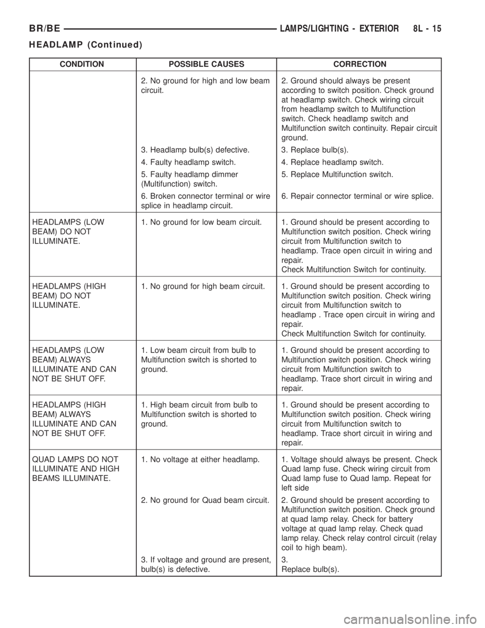
CONDITION POSSIBLE CAUSES CORRECTION
2. No ground for high and low beam
circuit.2. Ground should always be present
according to switch position. Check ground
at headlamp switch. Check wiring circuit
from headlamp switch to Multifunction
switch. Check headlamp switch and
Multifunction switch continuity. Repair circuit
ground.
3. Headlamp bulb(s) defective. 3. Replace bulb(s).
4. Faulty headlamp switch. 4. Replace headlamp switch.
5. Faulty headlamp dimmer
(Multifunction) switch.5. Replace Multifunction switch.
6. Broken connector terminal or wire
splice in headlamp circuit.6. Repair connector terminal or wire splice.
HEADLAMPS (LOW
BEAM) DO NOT
ILLUMINATE.1. No ground for low beam circuit. 1. Ground should be present according to
Multifunction switch position. Check wiring
circuit from Multifunction switch to
headlamp. Trace open circuit in wiring and
repair.
Check Multifunction Switch for continuity.
HEADLAMPS (HIGH
BEAM) DO NOT
ILLUMINATE.1. No ground for high beam circuit. 1. Ground should be present according to
Multifunction switch position. Check wiring
circuit from Multifunction switch to
headlamp . Trace open circuit in wiring and
repair.
Check Multifunction Switch for continuity.
HEADLAMPS (LOW
BEAM) ALWAYS
ILLUMINATE AND CAN
NOT BE SHUT OFF.1. Low beam circuit from bulb to
Multifunction switch is shorted to
ground.1. Ground should be present according to
Multifunction switch position. Check wiring
circuit from Multifunction switch to
headlamp. Trace short circuit in wiring and
repair.
HEADLAMPS (HIGH
BEAM) ALWAYS
ILLUMINATE AND CAN
NOT BE SHUT OFF.1. High beam circuit from bulb to
Multifunction switch is shorted to
ground.1. Ground should be present according to
Multifunction switch position. Check wiring
circuit from Multifunction switch to
headlamp. Trace short circuit in wiring and
repair.
QUAD LAMPS DO NOT
ILLUMINATE AND HIGH
BEAMS ILLUMINATE.1. No voltage at either headlamp. 1. Voltage should always be present. Check
Quad lamp fuse. Check wiring circuit from
Quad lamp fuse to Quad lamp. Repeat for
left side
2. No ground for Quad beam circuit. 2. Ground should be present according to
Multifunction switch position. Check ground
at quad lamp relay. Check for battery
voltage at quad lamp relay. Check quad
lamp relay. Check relay control circuit (relay
coil to high beam).
3. If voltage and ground are present,
bulb(s) is defective.3.
Replace bulb(s).
BR/BELAMPS/LIGHTING - EXTERIOR 8L - 15
HEADLAMP (Continued)