2002 DODGE RAM automatic transmission
[x] Cancel search: automatic transmissionPage 1880 of 2255
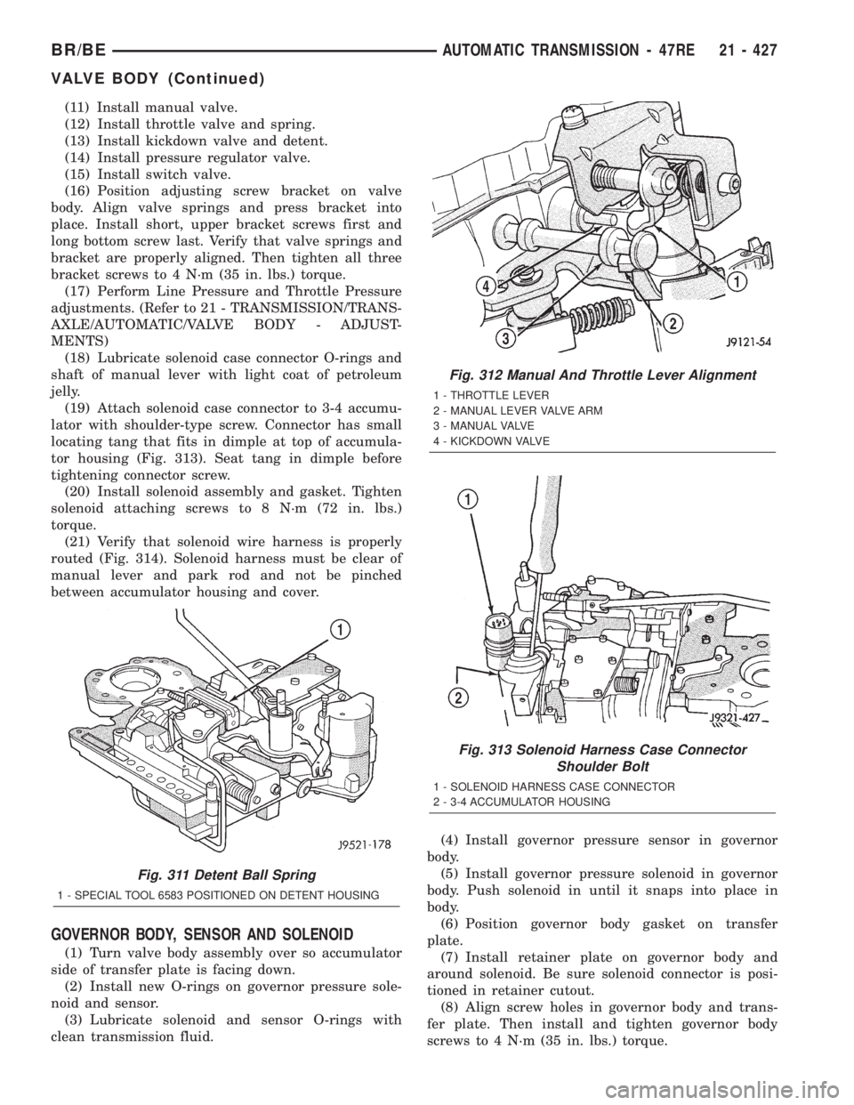
(11) Install manual valve.
(12) Install throttle valve and spring.
(13) Install kickdown valve and detent.
(14) Install pressure regulator valve.
(15) Install switch valve.
(16) Position adjusting screw bracket on valve
body. Align valve springs and press bracket into
place. Install short, upper bracket screws first and
long bottom screw last. Verify that valve springs and
bracket are properly aligned. Then tighten all three
bracket screws to 4 N´m (35 in. lbs.) torque.
(17) Perform Line Pressure and Throttle Pressure
adjustments. (Refer to 21 - TRANSMISSION/TRANS-
AXLE/AUTOMATIC/VALVE BODY - ADJUST-
MENTS)
(18) Lubricate solenoid case connector O-rings and
shaft of manual lever with light coat of petroleum
jelly.
(19) Attach solenoid case connector to 3-4 accumu-
lator with shoulder-type screw. Connector has small
locating tang that fits in dimple at top of accumula-
tor housing (Fig. 313). Seat tang in dimple before
tightening connector screw.
(20) Install solenoid assembly and gasket. Tighten
solenoid attaching screws to 8 N´m (72 in. lbs.)
torque.
(21) Verify that solenoid wire harness is properly
routed (Fig. 314). Solenoid harness must be clear of
manual lever and park rod and not be pinched
between accumulator housing and cover.
GOVERNOR BODY, SENSOR AND SOLENOID
(1) Turn valve body assembly over so accumulator
side of transfer plate is facing down.
(2) Install new O-rings on governor pressure sole-
noid and sensor.
(3) Lubricate solenoid and sensor O-rings with
clean transmission fluid.(4) Install governor pressure sensor in governor
body.
(5) Install governor pressure solenoid in governor
body. Push solenoid in until it snaps into place in
body.
(6) Position governor body gasket on transfer
plate.
(7) Install retainer plate on governor body and
around solenoid. Be sure solenoid connector is posi-
tioned in retainer cutout.
(8) Align screw holes in governor body and trans-
fer plate. Then install and tighten governor body
screws to 4 N´m (35 in. lbs.) torque.
Fig. 311 Detent Ball Spring
1 - SPECIAL TOOL 6583 POSITIONED ON DETENT HOUSING
Fig. 312 Manual And Throttle Lever Alignment
1 - THROTTLE LEVER
2 - MANUAL LEVER VALVE ARM
3 - MANUAL VALVE
4 - KICKDOWN VALVE
Fig. 313 Solenoid Harness Case Connector
Shoulder Bolt
1 - SOLENOID HARNESS CASE CONNECTOR
2 - 3-4 ACCUMULATOR HOUSING
BR/BEAUTOMATIC TRANSMISSION - 47RE 21 - 427
VALVE BODY (Continued)
Page 1881 of 2255
(9) Connect harness wires to governor pressure
solenoid and governor pressure sensor.
(10) Install fluid filter and pan.
(11) Lower vehicle.
(12) Fill transmission with recommended fluid and
road test vehicle to verify repair.
INSTALLATION
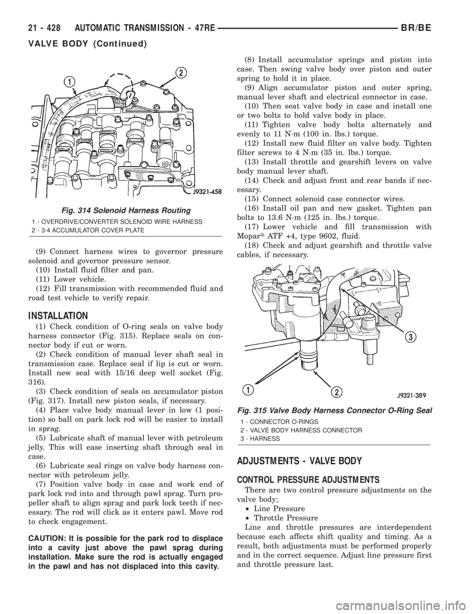
(1) Check condition of O-ring seals on valve body
harness connector (Fig. 315). Replace seals on con-
nector body if cut or worn.
(2) Check condition of manual lever shaft seal in
transmission case. Replace seal if lip is cut or worn.
Install new seal with 15/16 deep well socket (Fig.
316).
(3) Check condition of seals on accumulator piston
(Fig. 317). Install new piston seals, if necessary.
(4) Place valve body manual lever in low (1 posi-
tion) so ball on park lock rod will be easier to install
in sprag.
(5) Lubricate shaft of manual lever with petroleum
jelly. This will ease inserting shaft through seal in
case.
(6) Lubricate seal rings on valve body harness con-
nector with petroleum jelly.
(7) Position valve body in case and work end of
park lock rod into and through pawl sprag. Turn pro-
peller shaft to align sprag and park lock teeth if nec-
essary. The rod will click as it enters pawl. Move rod
to check engagement.
CAUTION: It is possible for the park rod to displace
into a cavity just above the pawl sprag during
installation. Make sure the rod is actually engaged
in the pawl and has not displaced into this cavity.(8) Install accumulator springs and piston into
case. Then swing valve body over piston and outer
spring to hold it in place.
(9) Align accumulator piston and outer spring,
manual lever shaft and electrical connector in case.
(10) Then seat valve body in case and install one
or two bolts to hold valve body in place.
(11) Tighten valve body bolts alternately and
evenly to 11 N´m (100 in. lbs.) torque.
(12) Install new fluid filter on valve body. Tighten
filter screws to 4 N´m (35 in. lbs.) torque.
(13) Install throttle and gearshift levers on valve
body manual lever shaft.
(14) Check and adjust front and rear bands if nec-
essary.
(15) Connect solenoid case connector wires.
(16) Install oil pan and new gasket. Tighten pan
bolts to 13.6 N´m (125 in. lbs.) torque.
(17) Lower vehicle and fill transmission with
MopartATF +4, type 9602, fluid.
(18) Check and adjust gearshift and throttle valve
cables, if necessary.
ADJUSTMENTS - VALVE BODY
CONTROL PRESSURE ADJUSTMENTS
There are two control pressure adjustments on the
valve body;
²Line Pressure
²Throttle Pressure
Line and throttle pressures are interdependent
because each affects shift quality and timing. As a
result, both adjustments must be performed properly
and in the correct sequence. Adjust line pressure first
and throttle pressure last.
Fig. 314 Solenoid Harness Routing
1 - OVERDRIVE/CONVERTER SOLENOID WIRE HARNESS
2 - 3-4 ACCUMULATOR COVER PLATE
Fig. 315 Valve Body Harness Connector O-Ring Seal
1 - CONNECTOR O-RINGS
2 - VALVE BODY HARNESS CONNECTOR
3 - HARNESS
21 - 428 AUTOMATIC TRANSMISSION - 47REBR/BE
VALVE BODY (Continued)
Page 1882 of 2255
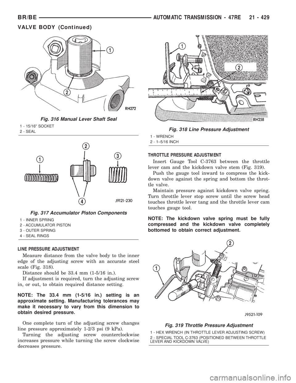
LINE PRESSURE ADJUSTMENT
Measure distance from the valve body to the inner
edge of the adjusting screw with an accurate steel
scale (Fig. 318).
Distance should be 33.4 mm (1-5/16 in.).
If adjustment is required, turn the adjusting screw
in, or out, to obtain required distance setting.
NOTE: The 33.4 mm (1-5/16 in.) setting is an
approximate setting. Manufacturing tolerances may
make it necessary to vary from this dimension to
obtain desired pressure.
One complete turn of the adjusting screw changes
line pressure approximately 1-2/3 psi (9 kPa).
Turning the adjusting screw counterclockwise
increases pressure while turning the screw clockwise
decreases pressure.THROTTLE PRESSURE ADJUSTMENT
Insert Gauge Tool C-3763 between the throttle
lever cam and the kickdown valve stem (Fig. 319).
Push the gauge tool inward to compress the kick-
down valve against the spring and bottom the throt-
tle valve.
Maintain pressure against kickdown valve spring.
Turn throttle lever stop screw until the screw head
touches throttle lever tang and the throttle lever cam
touches gauge tool.
NOTE: The kickdown valve spring must be fully
compressed and the kickdown valve completely
bottomed to obtain correct adjustment.
Fig. 316 Manual Lever Shaft Seal
1 - 15/16©© SOCKET
2 - SEAL
Fig. 317 Accumulator Piston Components
1 - INNER SPRING
2 - ACCUMULATOR PISTON
3 - OUTER SPRING
4 - SEAL RINGS
Fig. 318 Line Pressure Adjustment
1 - WRENCH
2 - 1±5/16 INCH
Fig. 319 Throttle Pressure Adjustment
1 - HEX WRENCH (IN THROTTLE LEVER ADJUSTING SCREW)
2 - SPECIAL TOOL C-3763 (POSITIONED BETWEEN THROTTLE
LEVER AND KICKDOWN VALVE)
BR/BEAUTOMATIC TRANSMISSION - 47RE 21 - 429
VALVE BODY (Continued)
Page 1884 of 2255
exception being when the road surface is covered by
ice and snow.
The low range reduction gear system is operative
in 4LO range only. This range is for extra pulling
power in off road situations. Low range reduction
ratio is 2.72:1.
A front axle disconnect system is used to achieve
two-wheel drive mode. The axle disconnect vacuum
motor is actuated by a vacuum switch on the transfer
case. The switch is operated by the transfer case
range rod.
SHIFT MECHANISM
The transfer case is operated by an adjustable floor
mounted shift linkage. The transfer case shift lever
is directly attached to the shift sector. The sector
operates the range and mode forks within the trans-
fer case.
A straight line shift pattern is used with a NEU-
TRAL detent. Lever range positions are imprinted in
the shift knob.
SHIFTING
The synchronizer components allow the transfer
case to be shifted between the 2H and 4H operating
ranges while the vehicle is in motion. The vehicle
must have the transmission placed in NEUTRAL, or
the clutch depressed in the case of a manual trans-
mission, and be moving less than 2-3 MPH when
shifting into the 4L operating range.
DIAGNOSIS AND TESTING - TRANSFER CASE
Before beginning repair on a suspected transfer
case malfunction, check all other driveline compo-
nents beforehand.
The actual cause of a problem may be related to
such items as: front hubs, axles, propeller shafts,
wheels and tires, transmission, or clutch instead. If
all other driveline components are in good condition
and operating properly, refer to the Diagnosis Chart
for further information.
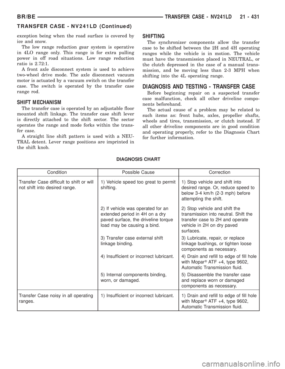
DIAGNOSIS CHART
Condition Possible Cause Correction
Transfer Case difficult to shift or will
not shift into desired range.1) Vehicle speed too great to permit
shifting.1) Stop vehicle and shift into
desired range. Or, reduce speed to
below 3-4 km/h (2-3 mph) before
attempting the shift.
2) If vehicle was operated for an
extended period in 4H on a dry
paved surface, the driveline torque
load may be causing a bind.2) Stop vehicle and shift the
transmission into neutral. Shift the
transfer case to 2H and operate
vehicle in 2H on dry paved
surfaces.
3) Transfer case external shift
linkage binding.3) Lubricate, repair, or replace
linkage bushings, or tighten loose
components as necessary.
4) Insufficient or incorrect lubricant. 4) Drain and refill to edge of fill hole
with MoparTATF +4, type 9602,
Automatic Transmission fluid.
5) Internal components binding,
worn, or damaged.5) Disassemble the transfer case
and replace worn or damaged
components as necessary.
Transfer Case noisy in all operating
ranges.1) Insufficient or incorrect lubricant. 1) Drain and refill to edge of fill hole
with MoparTATF +4, type 9602,
Automatic Transmission fluid.
BR/BETRANSFER CASE - NV241LD 21 - 431
TRANSFER CASE - NV241LD (Continued)
Page 1913 of 2255
EXTENSION HOUSING
BUSHING AND SEAL
REMOVAL
(1) Raise and support vehicle.
(2) Remove rear propeller shaft. (Refer to 3 - DIF-
FERENTIAL & DRIVELINE/PROPELLER SHAFT/
PROPELLER SHAFT - REMOVAL)
(3) Using a suitable pry tool or slide-hammer
mounted screw, remove the extension housing seal.
(4) Using Remover 8158, remove bushing from
extension housing.
INSTALLATION
(1) Clean fluid residue from sealing surface and
inspect for defects.
(2) Position replacement bushing in extension
housing with fluid port in bushing aligned with slot
in housing.
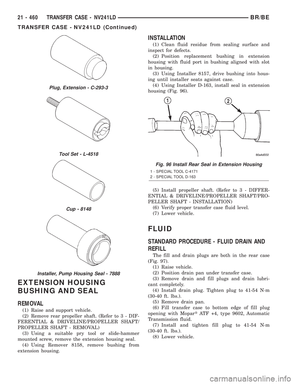
(3) Using Installer 8157, drive bushing into hous-
ing until installer seats against case.
(4) Using Installer D-163, install seal in extension
housing (Fig. 96).
(5) Install propeller shaft. (Refer to 3 - DIFFER-
ENTIAL & DRIVELINE/PROPELLER SHAFT/PRO-
PELLER SHAFT - INSTALLATION)
(6) Verify proper transfer case fluid level.
(7) Lower vehicle.
FLUID
STANDARD PROCEDURE - FLUID DRAIN AND
REFILL
The fill and drain plugs are both in the rear case
(Fig. 97).
(1) Raise vehicle.
(2) Position drain pan under transfer case.
(3) Remove drain and fill plugs and drain lubri-
cant completely.
(4) Install drain plug. Tighten plug to 41-54 N´m
(30-40 ft. lbs.).
(5) Remove drain pan.
(6) Fill transfer case to bottom edge of fill plug
opening with MopartATF +4, type 9602, Automatic
Transmission fluid.
(7) Install and tighten fill plug to 41-54 N´m
(30-40 ft. lbs.).
(8) Lower vehicle.
Plug, Extension - C-293-3
Tool Set - L-4518
Cup - 8148
Installer, Pump Housing Seal - 7888
Fig. 96 Install Rear Seal in Extension Housing
1 - SPECIAL TOOL C-4171
2 - SPECIAL TOOL D-163
21 - 460 TRANSFER CASE - NV241LDBR/BE
TRANSFER CASE - NV241LD (Continued)
Page 1921 of 2255
DIAGNOSIS CHART
Condition Possible Cause Correction
Transfer Case difficult to shift or will
not shift into desired range.1) Vehicle speed too great to permit
shifting.1) Stop vehicle and shift into
desired range. Or, reduce speed to
below 3-4 km/h (2-3 mph) before
attempting the shift.
2) If vehicle was operated for an
extended period in 4H on a dry
paved surface, the driveline torque
load may be causing a bind.
2) Stop vehicle and shift the
transmission into neutral. Shift the
transfer case to 2H and operate
vehicle in 2H on dry paved surfaces.
3) Transfer case external shift
linkage binding.3) Lubricate, repair, or replace
linkage bushings, or tighten loose
components as necessary.
4) Insufficient or incorrect lubricant. 4) Drain and refill to edge of fill hole
with MoparTATF +4, type 9602,
Automatic Transmission fluid.
5) Internal components binding,
worn, or damaged.5) Disassemble the transfer case
and replace worn or damaged
components as necessary.
Transfer Case noisy in all operating
ranges.1) Insufficient or incorrect lubricant. 1) Drain and refill to edge of fill hole
with MoparTATF +4, type 9602,
Automatic Transmission fluid.
Noisy in, or jumps out of, four wheel
drive low range.1) Transfer case not completely
engaged in 4L position.1) With the transmission in
NEUTRAL, or the clutch depressed
in the case of a manual
transmission and the vehicle moving
under 3-4 km/h (2-3 mph), shift the
transfer case to NEUTRAL and then
shift into the 4L position.
2) Shift linkage out of adjustment. 2) Adjust linkage.
3) Shift linkage loose or binding. 3) Tighten, lubricate, or repair
linkage as necessary.
4) Range fork damaged, inserts worn,
or fork is binding on the shift rail.4) Disassemble unit and repair as
necessary.
5) Low range gear worn or
damaged.5) Disassemble unit and repair as
necessary.
Lubricant leaking from output shaft
seal or vent.1) Transfer case overfilled. 1) Drain lubricant to the correct
level.
2) Vent closed or restricted. 2) Clear or replace vent as
necessary.
3) Output shaft seals damaged or
installed incorrectly.3) Replace seal as necessary.
Check to ensure that another
component, the propeller shaft slip
yoke for example, is not causing
damage to seal.
Abnormal tire wear. 1) Extended operation on hard, dry
surfaces in the 4H position.1) Operate vehicle in the 2H
position on hard, dry surfaces.
21 - 468 TRANSFER CASE - NV241HDBR/BE
TRANSFER CASE - NV241HD (Continued)
Page 1950 of 2255
EXTENSION HOUSING
BUSHING AND SEAL
REMOVAL
(1) Raise and support vehicle.
(2) Remove rear propeller shaft. (Refer to 3 - DIF-
FERENTIAL & DRIVELINE/PROPELLER SHAFT/
PROPELLER SHAFT - REMOVAL)
(3) Using a suitable pry tool or slide-hammer
mounted screw, remove the extension housing seal.
(4) Using Remover 8155, remove bushing from
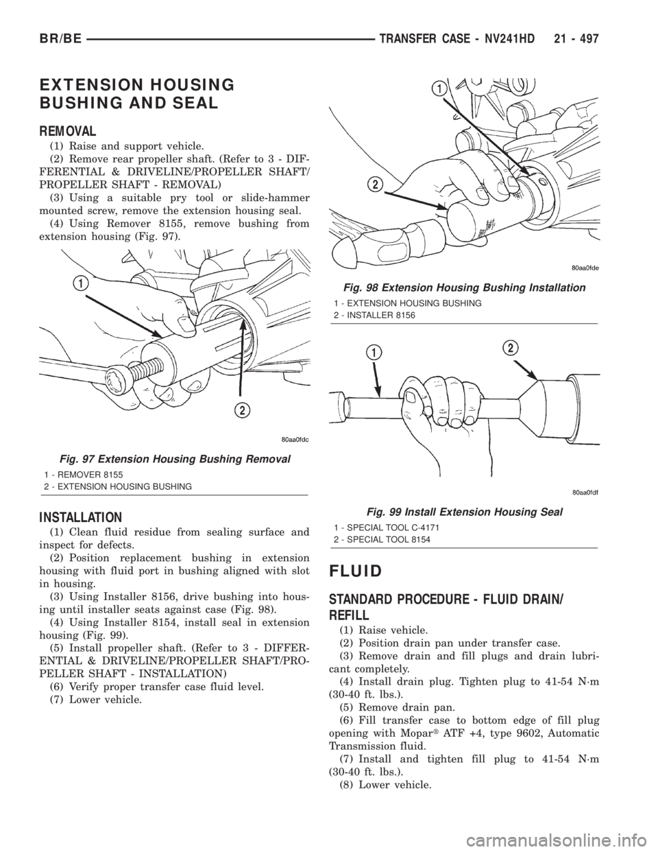
extension housing (Fig. 97).
INSTALLATION
(1) Clean fluid residue from sealing surface and
inspect for defects.
(2) Position replacement bushing in extension
housing with fluid port in bushing aligned with slot
in housing.
(3) Using Installer 8156, drive bushing into hous-
ing until installer seats against case (Fig. 98).
(4) Using Installer 8154, install seal in extension
housing (Fig. 99).
(5) Install propeller shaft. (Refer to 3 - DIFFER-
ENTIAL & DRIVELINE/PROPELLER SHAFT/PRO-
PELLER SHAFT - INSTALLATION)
(6) Verify proper transfer case fluid level.
(7) Lower vehicle.
FLUID
STANDARD PROCEDURE - FLUID DRAIN/
REFILL
(1) Raise vehicle.
(2) Position drain pan under transfer case.
(3) Remove drain and fill plugs and drain lubri-
cant completely.
(4) Install drain plug. Tighten plug to 41-54 N´m
(30-40 ft. lbs.).
(5) Remove drain pan.
(6) Fill transfer case to bottom edge of fill plug
opening with MopartATF +4, type 9602, Automatic
Transmission fluid.
(7) Install and tighten fill plug to 41-54 N´m
(30-40 ft. lbs.).
(8) Lower vehicle.
Fig. 97 Extension Housing Bushing Removal
1 - REMOVER 8155
2 - EXTENSION HOUSING BUSHING
Fig. 98 Extension Housing Bushing Installation
1 - EXTENSION HOUSING BUSHING
2 - INSTALLER 8156
Fig. 99 Install Extension Housing Seal
1 - SPECIAL TOOL C-4171
2 - SPECIAL TOOL 8154
BR/BETRANSFER CASE - NV241HD 21 - 497
Page 2072 of 2255
INSTRUMENT PANEL SYSTEM
TABLE OF CONTENTS
page page
INSTRUMENT PANEL SYSTEM
DESCRIPTION........................105
OPERATION..........................106
ASH RECEIVER
REMOVAL............................107
INSTALLATION........................107
CLUSTER BEZEL
REMOVAL............................108
INSTALLATION........................108
CUBBY BIN
REMOVAL............................108
INSTALLATION........................109
CUP HOLDER
REMOVAL............................109
INSTALLATION........................110
GLOVE BOX
REMOVAL
REMOVAL..........................110
DISASSEMBLY - GLOVE BOX...........110
ASSEMBLY - GLOVE BOX................111INSTALLATION........................111
GLOVE BOX LATCH STRIKER
REMOVAL............................111
INSTALLATION........................112
GLOVE BOX OPENING UPPER TRIM
REMOVAL............................112
INSTALLATION........................112
INSTRUMENT PANEL TOP COVER
REMOVAL............................113
INSTALLATION........................113
STEERING COLUMN OPENING COVER
REMOVAL............................113
INSTALLATION........................114
STORAGE BIN
REMOVAL............................114
INSTALLATION........................114
INSTRUMENT PANEL ASSEMBLY
REMOVAL............................115
INSTALLATION........................117
INSTRUMENT PANEL SYSTEM
DESCRIPTION
The instrument panel is located at the front of the
passenger compartment. This instrument panel is
molded from a blend of various plastics that are
mechanically attached to the vehicle. Colors are
molded into the plastic components to minimize
appearance degradation from scratches or abrasions.
The panel components are internally ribbed and riv-
eted to steel reinforcements for additional structural
integrity and dimensional stability. The instrument
panel surface components are designed to deform
upon impact without breaking. This type of construc-
tion provides improved energy absorption which, in
conjunction with the dual airbags and seat belts,
helps to improve occupant protection.
The top of the instrument panel is secured to the
top of the dash panel near the base of the windshield
using screws. An end bracket integral to each end of
the instrument panel structure is secured to each
cowl side inner panel with a screw. A stamped metal
bracket supports the center of the instrument panel
by securing it to the top of the floor panel transmis-
sion tunnel below the instrument panel with screws.
The instrument cluster, radio, heater-air conditioner
control, passenger airbag, glove box, electrical junc-tion block, Central Timer Module (CTM), accessory
switches, ash receiver, cigar lighter, accessory power
outlet, park brake release handle, inside hood release
handle, as well as numerous other components are
secured to and supported by this unit.
The instrument panel for this vehicle includes the
following major features:
²Cluster Bezel- This molded plastic bezel is
secured with snap clips to the instrument panel sup-
porting structure. It trims out the edges of the head-
lamp switch, instrument cluster, radio, heater-air
conditioner controls, passenger airbag on-off switch,
and the heated seat switches on vehicles so equipped.
On vehicles without the heated seat option, a small
storage cubby bin is provided in the cluster bezel.
This bezel also incorporates three completely adjust-
able panel outlets for the climate control system, and
fills the opening between the instrument cluster and
the top of the steering column where it passes
through the instrument panel.
²Cup Holder/Storage Bin- Vehicles equipped
with an automatic transmission feature a latching
fold-down, adjustable cup holder located on the lower
instrument panel between the glove box and the ash
receiver. Vehicles equipped with a manual transmis-
sion have a lighted storage bin on the instrument
panel in place of the cup holder.
BR/BEINSTRUMENT PANEL SYSTEM 23 - 105