2002 DODGE RAM oil
[x] Cancel search: oilPage 128 of 2255
PINION GEAR/RING GEAR/
TONE RING
REMOVAL
NOTE: The ring and pinion gears are service as a
matched set. Never replace ring gear without
replacing the matched pinion gear.
(1) Remove differential from housing.
(2) Place differential case in a suitable vise with
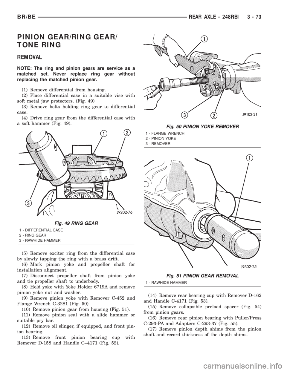
soft metal jaw protectors. (Fig. 49)
(3) Remove bolts holding ring gear to differential
case.
(4) Drive ring gear from the differential case with
a soft hammer (Fig. 49).
(5) Remove exciter ring from the differential case
by slowly tapping the ring with a brass drift.
(6) Mark pinion yoke and propeller shaft for
installation alignment.
(7) Disconnect propeller shaft from pinion yoke
and tie propeller shaft to underbody.
(8) Hold yoke with Yoke Holder 6719A and remove
pinion yoke nut and washer.
(9) Remove pinion yoke with Remover C-452 and
Flange Wrench C-3281 (Fig. 50).
(10) Remove pinion gear from housing (Fig. 51).
(11) Remove pinion seal with a slide hammer or
suitable pry bar.
(12) Remove oil slinger, if equipped, and front pin-
ion bearing.
(13) Remove front pinion bearing cup with
Remover D-158 and Handle C±4171 (Fig. 52).(14) Remove rear bearing cup with Remover D-162
and Handle C-4171 (Fig. 53).
(15) Remove collapsible preload spacer (Fig. 54)
from pinion gears.
(16) Remove rear pinion bearing with Puller/Press
C-293-PA and Adapters C-293-37 (Fig. 55).
(17) Remove pinion depth shims from the pinion
shaft and record thickness of the depth shims.
Fig. 49 RING GEAR
1 - DIFFERENTIAL CASE
2 - RING GEAR
3 - RAWHIDE HAMMER
Fig. 50 PINION YOKE REMOVER
1 - FLANGE WRENCH
2 - PINION YOKE
3 - REMOVER
Fig. 51 PINION GEAR REMOVAL
1 - RAWHIDE HAMMER
BR/BEREAR AXLE - 248RBI 3 - 73
Page 130 of 2255
INSTALLATION
(1) Apply Mopar Door Ease stick or equivalent
lubricant to outside surface of bearing cups.
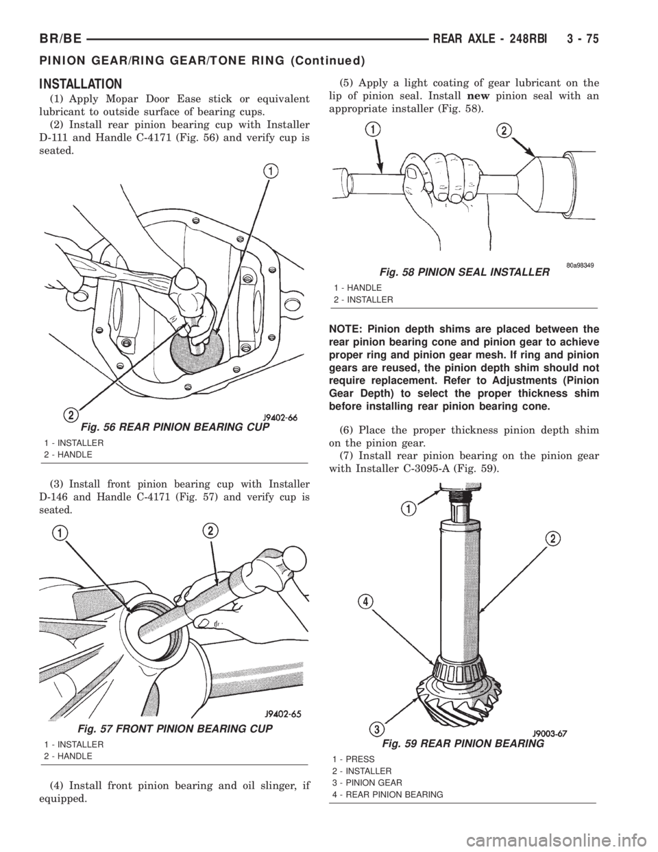
(2) Install rear pinion bearing cup with Installer
D-111 and Handle C-4171 (Fig. 56) and verify cup is
seated.
(3)
Install front pinion bearing cup with Installer
D-146 and Handle C-4171 (Fig. 57) and verify cup is
seated.
(4) Install front pinion bearing and oil slinger, if
equipped.(5) Apply a light coating of gear lubricant on the
lip of pinion seal. Installnewpinion seal with an
appropriate installer (Fig. 58).
NOTE: Pinion depth shims are placed between the
rear pinion bearing cone and pinion gear to achieve
proper ring and pinion gear mesh. If ring and pinion
gears are reused, the pinion depth shim should not
require replacement. Refer to Adjustments (Pinion
Gear Depth) to select the proper thickness shim
before installing rear pinion bearing cone.
(6) Place the proper thickness pinion depth shim
on the pinion gear.
(7) Install rear pinion bearing on the pinion gear
with Installer C-3095-A (Fig. 59).
Fig. 59 REAR PINION BEARING
1 - PRESS
2 - INSTALLER
3 - PINION GEAR
4 - REAR PINION BEARING
Fig. 56 REAR PINION BEARING CUP
1 - INSTALLER
2 - HANDLE
Fig. 57 FRONT PINION BEARING CUP
1 - INSTALLER
2 - HANDLE
Fig. 58 PINION SEAL INSTALLER
1 - HANDLE
2 - INSTALLER
BR/BEREAR AXLE - 248RBI 3 - 75
PINION GEAR/RING GEAR/TONE RING (Continued)
Page 131 of 2255
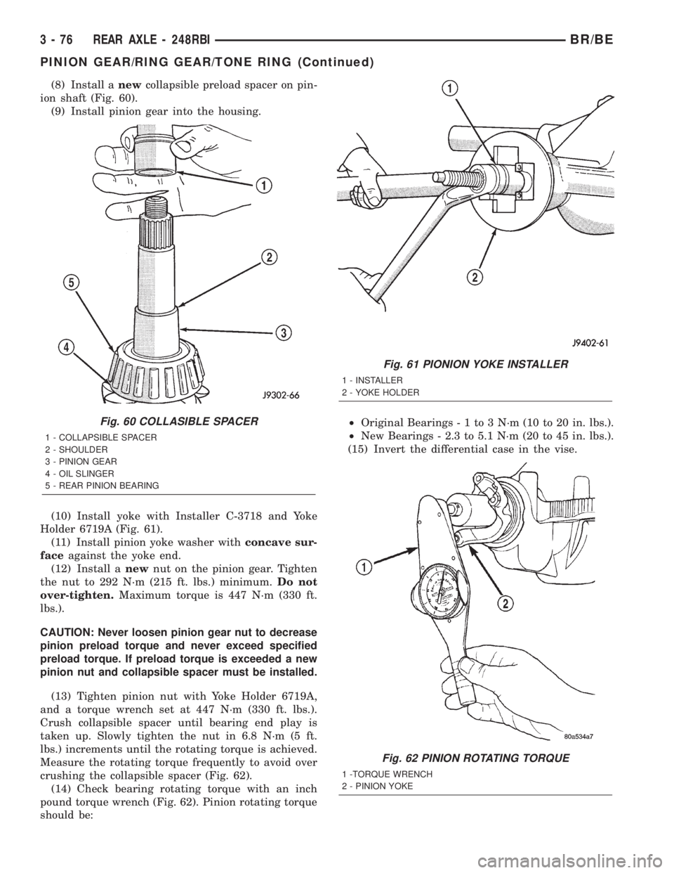
(8) Install anewcollapsible preload spacer on pin-
ion shaft (Fig. 60).
(9) Install pinion gear into the housing.
(10) Install yoke with Installer C-3718 and Yoke
Holder 6719A (Fig. 61).
(11) Install pinion yoke washer withconcave sur-
faceagainst the yoke end.
(12) Install anewnut on the pinion gear. Tighten
the nut to 292 N´m (215 ft. lbs.) minimum.Do not
over-tighten.Maximum torque is 447 N´m (330 ft.
lbs.).
CAUTION: Never loosen pinion gear nut to decrease
pinion preload torque and never exceed specified
preload torque. If preload torque is exceeded a new
pinion nut and collapsible spacer must be installed.
(13) Tighten pinion nut with Yoke Holder 6719A,
and a torque wrench set at 447 N´m (330 ft. lbs.).
Crush collapsible spacer until bearing end play is
taken up. Slowly tighten the nut in 6.8 N´m (5 ft.
lbs.) increments until the rotating torque is achieved.
Measure the rotating torque frequently to avoid over
crushing the collapsible spacer (Fig. 62).
(14) Check bearing rotating torque with an inch
pound torque wrench (Fig. 62). Pinion rotating torque
should be:²Original Bearings-1to3N´m(10to20in.lbs.).
²New Bearings - 2.3 to 5.1 N´m (20 to 45 in. lbs.).
(15) Invert the differential case in the vise.
Fig. 60 COLLASIBLE SPACER
1 - COLLAPSIBLE SPACER
2 - SHOULDER
3 - PINION GEAR
4 - OIL SLINGER
5 - REAR PINION BEARING
Fig. 61 PIONION YOKE INSTALLER
1 - INSTALLER
2 - YOKE HOLDER
Fig. 62 PINION ROTATING TORQUE
1 -TORQUE WRENCH
2 - PINION YOKE
3 - 76 REAR AXLE - 248RBIBR/BE
PINION GEAR/RING GEAR/TONE RING (Continued)
Page 138 of 2255

(3) Install shock absorbers and tighten to specifica-
tions.
(4) Install RWAL sensor to the differential hous-
ing, if necessary.
(5) Install parking brake cables and cable brackets
(6) Install brake hose to the axle junction block.
(7) Install axle vent hose.
(8) Install propeller shaft with reference marks
aligned.
(9) Install wheels and tires assemblies.
(10) Add gear lubricant, if necessary.
(11) Remove lift from the axle and lower the vehi-
cle.
ADJUSTMENTS
Ring and pinion gears are supplied as matched
sets only. The identifying numbers for the ring and
pinion gear are etched onto each gear (Fig. 4). A plus
(+) number, minus (±) number or zero (0) is etched
onto the pinion gear. This number is the amount (in
thousandths of an inch) the depth varies from the
standard depth setting of a pinion etched with a (0).
The standard setting from the center line of the ring
gear to the back face of the pinion is 136.53 mm
(5.375 in.). The standard depth provides the best
gear tooth contact pattern. Refer to Backlash and
Contact Pattern in this section for additional infor-
mation.
Compensation for pinion depth variance is
achieved with a select shim/oil baffle. The shims are
placed between the rear pinion bearing and the pin-
ion gear head (Fig. 5).
If a new gear set is being installed, note the depth
variance etched into both the original and replace-
ment pinion. Add or subtract this number from the
thickness of the original depth shim/oil slinger to
compensate for the difference in the depth variances.
Refer to the Depth Variance chart.
Note where Old and New Pinion Marking columns
intersect. Intersecting figure represents plus or
minus the amount needed.
Note the etched number on the face of the pinion
gear head (±1, ±2, 0, +1, +2, etc.). The numbers rep-
resent thousands of an inch deviation from the stan-
dard. If the number is negative, add that value to the
required thickness of the depth shims. If the number
is positive, subtract that value from the thickness of
the depth shim. If the number is 0 no change is nec-
essary.Fig. 4 PINION GEAR ID NUMBERS
1 - PRODUCTION NUMBERS
2 - PINION GEAR DEPTH VARIANCE
3 - GEAR MATCHING NUMBER
Fig. 5 SHIM LOCATIONS
1 - PINION GEAR DEPTH SHIM/OIL BAFFLE
2 - DIFFERENTIAL BEARING SHIM
BR/BEREAR AXLE - 267RBI 3 - 83
REAR AXLE - 267RBI (Continued)
Page 140 of 2255

(5) Install differential bearing caps on arbor discs
and snug the bearing cap bolts. Then cross tighten
cap bolts to 108 N´m (80 ft. lbs.).
(6) Assemble Dial Indicator C-3339 into Scooter
Block D-115-2 and secure set screw.
(7) Position Scooter Block/Dial Indicator flush on
the pinion height block. Hold scooter block and zero
the dial indicator.
(8) Slowly slide the scooter block across the pinion
height block over to the arbor (Fig. 9). Move the
scooter block till dial indicator crests the arbor, then
record the highest reading.
(9) Select a shim/oil baffle equal to the dial indica-
tor reading plus the pinion depth variance number
etched in the face of the pinion (Fig. 4). For example,
if the depth variance is ±2, add +0.002 in. to the dial
indicator reading.
DIFFERENTIAL SIDE BEARING PRELOAD AND
GEAR BACKLASH
Differential side bearing preload and gear backlash is
achieved by selective shims positioned behind the differ-
ential side bearing cones. The proper shim thickness
can be determined using slip-fit Dummy Bearings D-343
in place of the differential side bearings and a Dial Indi-
cator C-3339. Before proceeding with the differential
bearing preload and gear backlash measurements, mea-
sure the pinion gear depth and prepare the pinion for
installation. Establishing proper pinion gear depth is
essential to establishing gear backlash and tooth con-
tact patterns. After the overall shim thickness to take
up differential side play is measured, the pinion is
installed, and the gear backlash shim thickness is mea-
sured. The overall shim thickness is the total of the dial
indicator reading and the preload specification addedtogether. The gear backlash measurement determines
the thickness of the shim used on the ring gear side of
the differential case. Subtract the gear backlash shim
thickness from the total overall shim thickness and
select that amount for the pinion gear side of the differ-
ential (Fig. 10). Differential shim measurements are
performed with spreader W-129-B removed.
Fig. 8 GAUGE TOOLS IN HOUSING
1 - ARBOR DISC
2 - PINION BLOCK
3 - ARBOR
4 - PINION HEIGHT BLOCK
Fig. 9 PINION GEAR DEPTH MEASUREMENT
1 - ARBOR
2 - SCOOTER BLOCK
3 - DIAL INDICATOR
Fig. 10 SHIM LOCATIONS
1 - PINION GEAR DEPTH SHIM/OIL BAFFLE
2 - DIFFERENTIAL BEARING SHIM
BR/BEREAR AXLE - 267RBI 3 - 85
REAR AXLE - 267RBI (Continued)
Page 151 of 2255
DIFFERENTIAL
REMOVAL
(1) Raise and support the vehicle.
(2) Remove fill hole plug from the differential
housing cover.
(3) Remove differential housing cover and drain
lubricant from the housing.
(4) Clean the housing cavity with a flushing oil,
light engine oil or lint free cloth.Do not use water,
steam, kerosene or gasoline for cleaning.
(5) Remove axle shafts.
(6) Note the orientation of the installation refer-
ence letters stamped on the bearing caps and hous-
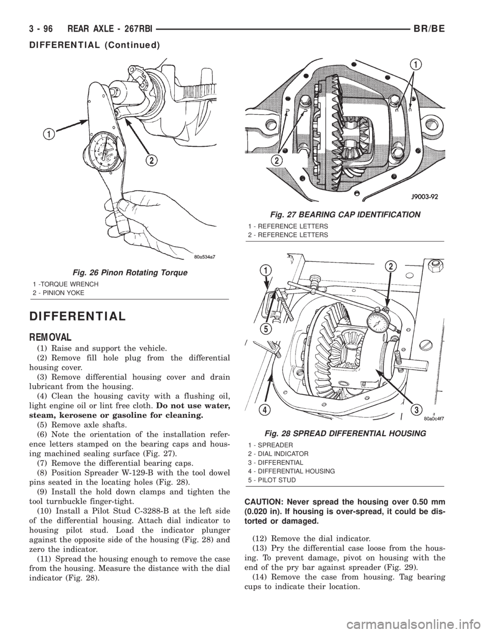
ing machined sealing surface (Fig. 27).
(7) Remove the differential bearing caps.
(8) Position Spreader W-129-B with the tool dowel
pins seated in the locating holes (Fig. 28).
(9) Install the hold down clamps and tighten the
tool turnbuckle finger-tight.
(10) Install a Pilot Stud C-3288-B at the left side
of the differential housing. Attach dial indicator to
housing pilot stud. Load the indicator plunger
against the opposite side of the housing (Fig. 28) and
zero the indicator.
(11) Spread the housing enough to remove the case
from the housing. Measure the distance with the dial
indicator (Fig. 28).CAUTION: Never spread the housing over 0.50 mm
(0.020 in). If housing is over-spread, it could be dis-
torted or damaged.
(12) Remove the dial indicator.
(13) Pry the differential case loose from the hous-
ing. To prevent damage, pivot on housing with the
end of the pry bar against spreader (Fig. 29).
(14) Remove the case from housing. Tag bearing
cups to indicate their location.
Fig. 26 Pinon Rotating Torque
1 -TORQUE WRENCH
2 - PINION YOKE
Fig. 27 BEARING CAP IDENTIFICATION
1 - REFERENCE LETTERS
2 - REFERENCE LETTERS
Fig. 28 SPREAD DIFFERENTIAL HOUSING
1 - SPREADER
2 - DIAL INDICATOR
3 - DIFFERENTIAL
4 - DIFFERENTIAL HOUSING
5 - PILOT STUD
3 - 96 REAR AXLE - 267RBIBR/BE
DIFFERENTIAL (Continued)
Page 158 of 2255
PINION GEAR/RING GEAR/
TONE RING
REMOVAL
NOTE: The ring and pinion gears are service in a
matched set. Do not replace the ring gear without
replacing the matched pinion gear.
(1) Remove differential from axle housing.
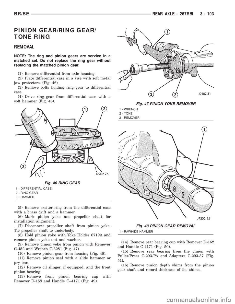
(2) Place differential case in a vise with soft metal
jaw protectors. (Fig. 46)
(3) Remove bolts holding ring gear to differential
case.
(4) Drive ring gear from differential case with a
soft hammer (Fig. 46).
(5) Remove exciter ring from the differential case
with a brass drift and a hammer.
(6) Mark pinion yoke and propeller shaft for
installation alignment.
(7) Disconnect propeller shaft from pinion yoke.
Tie propeller shaft to underbody.
(8) Hold pinion yoke with Yoke Holder 6719A and
remove pinion yoke nut and washer.
(9) Remove pinion yoke from pinion with Remover
C-452 and Wrench C-3281 (Fig. 47).
(10) Remove pinion gear from housing (Fig. 48).
(11) Remove pinion seal with a slide hammer or
pry bar.
(12) Remove oil slinger, if equipped, and the front
pinion bearing.
(13) Remove front pinion bearing cup with
Remover D-158 and Handle C±4171 (Fig. 49).(14) Remove rear bearing cup with Remover D-162
and Handle C-4171 (Fig. 50).
(15) Remove rear bearing from the pinion with
Puller/Press C-293-PA and Adapters C-293-37 (Fig.
51).
(16) Remove pinion depth shims from the pinion
gear shaft and record thickness of the shims.
Fig. 46 RING GEAR
1 - DIFFERENTIAL CASE
2 - RING GEAR
3 - HAMMER
Fig. 47 PINION YOKE REMOVER
1 - WRENCH
2 - YOKE
3 - REMOVER
Fig. 48 PINION GEAR REMOVAL
1 - RAWHIDE HAMMER
BR/BEREAR AXLE - 267RBI 3 - 103
Page 160 of 2255
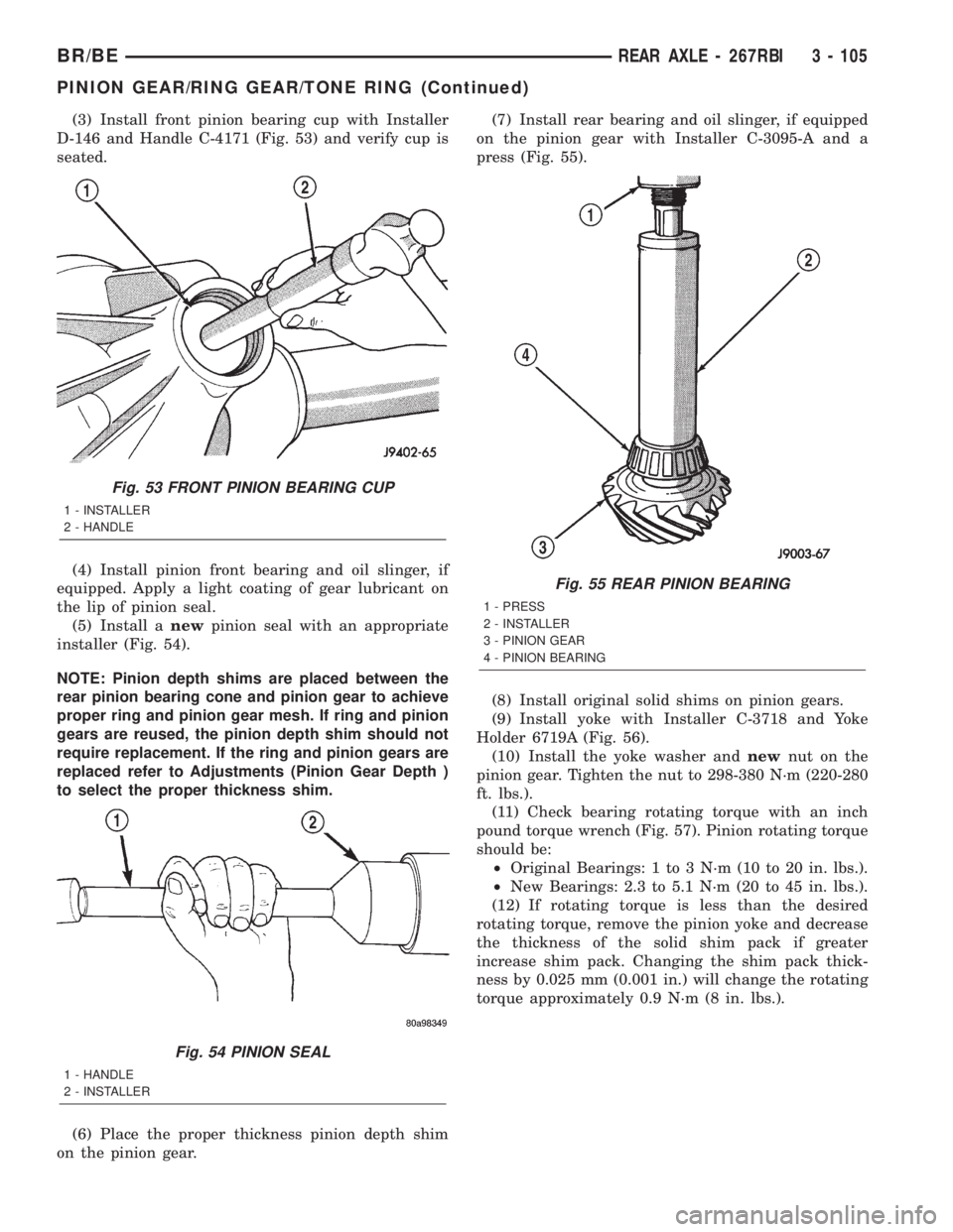
(3) Install front pinion bearing cup with Installer
D-146 and Handle C-4171 (Fig. 53) and verify cup is
seated.
(4) Install pinion front bearing and oil slinger, if
equipped. Apply a light coating of gear lubricant on
the lip of pinion seal.
(5) Install anewpinion seal with an appropriate
installer (Fig. 54).
NOTE: Pinion depth shims are placed between the
rear pinion bearing cone and pinion gear to achieve
proper ring and pinion gear mesh. If ring and pinion
gears are reused, the pinion depth shim should not
require replacement. If the ring and pinion gears are
replaced refer to Adjustments (Pinion Gear Depth )
to select the proper thickness shim.
(6) Place the proper thickness pinion depth shim
on the pinion gear.(7) Install rear bearing and oil slinger, if equipped
on the pinion gear with Installer C-3095-A and a
press (Fig. 55).
(8) Install original solid shims on pinion gears.
(9) Install yoke with Installer C-3718 and Yoke
Holder 6719A (Fig. 56).
(10) Install the yoke washer andnewnut on the
pinion gear. Tighten the nut to 298-380 N´m (220-280
ft. lbs.).
(11) Check bearing rotating torque with an inch
pound torque wrench (Fig. 57). Pinion rotating torque
should be:
²Original Bearings: 1 to 3 N´m (10 to 20 in. lbs.).
²New Bearings: 2.3 to 5.1 N´m (20 to 45 in. lbs.).
(12) If rotating torque is less than the desired
rotating torque, remove the pinion yoke and decrease
the thickness of the solid shim pack if greater
increase shim pack. Changing the shim pack thick-
ness by 0.025 mm (0.001 in.) will change the rotating
torque approximately 0.9 N´m (8 in. lbs.).
Fig. 53 FRONT PINION BEARING CUP
1 - INSTALLER
2 - HANDLE
Fig. 54 PINION SEAL
1 - HANDLE
2 - INSTALLER
Fig. 55 REAR PINION BEARING
1 - PRESS
2 - INSTALLER
3 - PINION GEAR
4 - PINION BEARING
BR/BEREAR AXLE - 267RBI 3 - 105
PINION GEAR/RING GEAR/TONE RING (Continued)