2002 DODGE RAM oil
[x] Cancel search: oilPage 86 of 2255
AXLE SHAFT SEALS
REMOVAL
(1) Remove hub bearings and axle shafts.
(2) Remove axle shaft seal from the differential
housing with a long drift or punch.Be careful not
to damage housing.
(3) Clean the inside perimeter of the differential
housing with fine crocus cloth.
INSTALLATION
(1) Apply a light film of oil to the inside lip of the
new axle shaft seal.
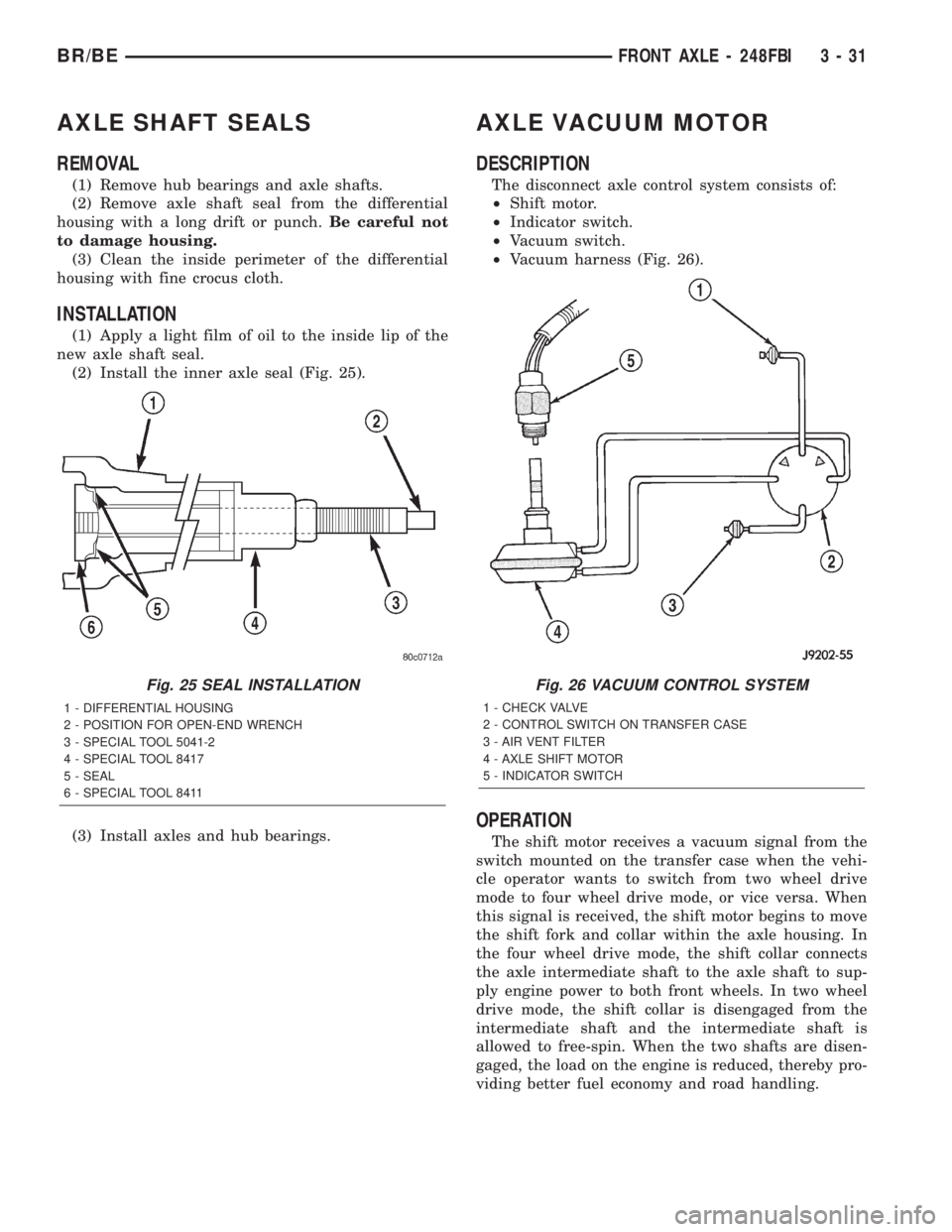
(2) Install the inner axle seal (Fig. 25).
(3) Install axles and hub bearings.
AXLE VACUUM MOTOR
DESCRIPTION
The disconnect axle control system consists of:
²Shift motor.
²Indicator switch.
²Vacuum switch.
²Vacuum harness (Fig. 26).
OPERATION
The shift motor receives a vacuum signal from the
switch mounted on the transfer case when the vehi-
cle operator wants to switch from two wheel drive
mode to four wheel drive mode, or vice versa. When
this signal is received, the shift motor begins to move
the shift fork and collar within the axle housing. In
the four wheel drive mode, the shift collar connects
the axle intermediate shaft to the axle shaft to sup-
ply engine power to both front wheels. In two wheel
drive mode, the shift collar is disengaged from the
intermediate shaft and the intermediate shaft is
allowed to free-spin. When the two shafts are disen-
gaged, the load on the engine is reduced, thereby pro-
viding better fuel economy and road handling.
Fig. 25 SEAL INSTALLATION
1 - DIFFERENTIAL HOUSING
2 - POSITION FOR OPEN-END WRENCH
3 - SPECIAL TOOL 5041-2
4 - SPECIAL TOOL 8417
5 - SEAL
6 - SPECIAL TOOL 8411
Fig. 26 VACUUM CONTROL SYSTEM
1 - CHECK VALVE
2 - CONTROL SWITCH ON TRANSFER CASE
3 - AIR VENT FILTER
4 - AXLE SHIFT MOTOR
5 - INDICATOR SWITCH
BR/BEFRONT AXLE - 248FBI 3 - 31
Page 89 of 2255
REMOVAL
(1) Disconnect the vacuum and wiring connector
from the shift housing.
(2) Remove indicator switch.
(3) Remove shift motor housing cover, gasket and
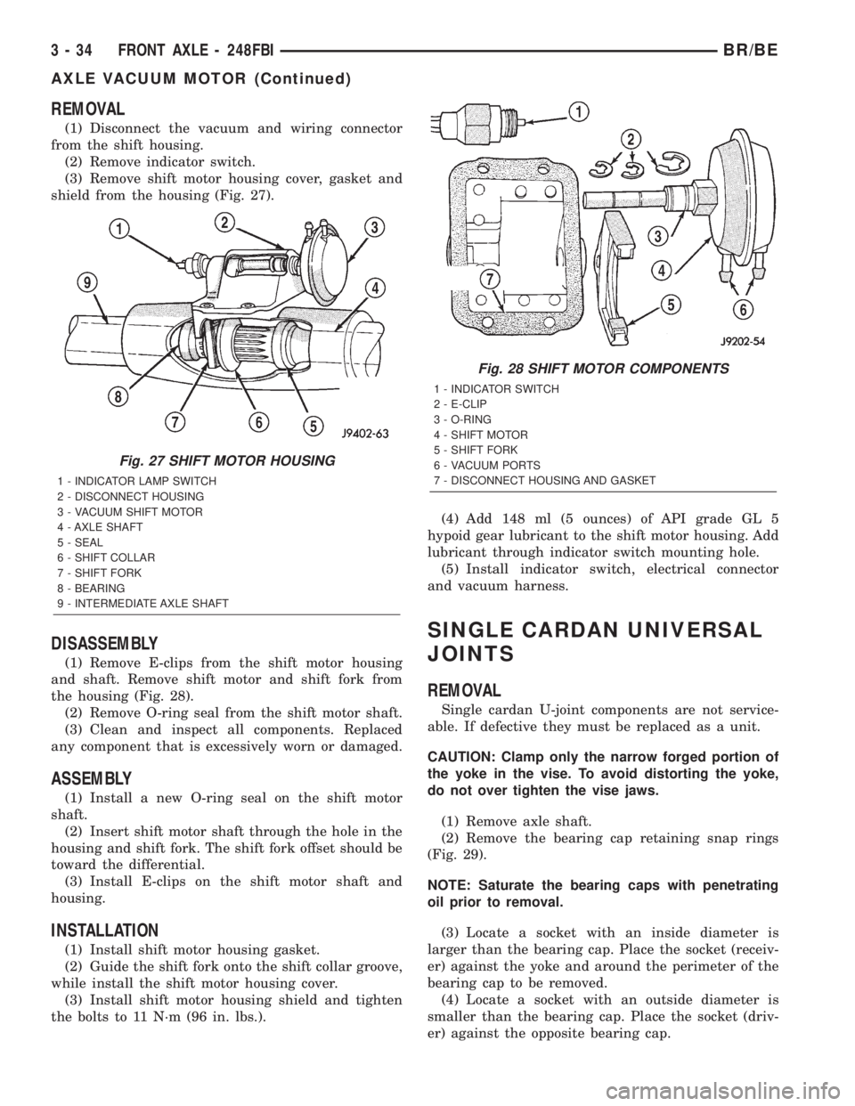
shield from the housing (Fig. 27).
DISASSEMBLY
(1) Remove E-clips from the shift motor housing
and shaft. Remove shift motor and shift fork from
the housing (Fig. 28).
(2) Remove O-ring seal from the shift motor shaft.
(3) Clean and inspect all components. Replaced
any component that is excessively worn or damaged.
ASSEMBLY
(1) Install a new O-ring seal on the shift motor
shaft.
(2) Insert shift motor shaft through the hole in the
housing and shift fork. The shift fork offset should be
toward the differential.
(3) Install E-clips on the shift motor shaft and
housing.
INSTALLATION
(1) Install shift motor housing gasket.
(2) Guide the shift fork onto the shift collar groove,
while install the shift motor housing cover.
(3) Install shift motor housing shield and tighten
the bolts to 11 N´m (96 in. lbs.).(4) Add 148 ml (5 ounces) of API grade GL 5
hypoid gear lubricant to the shift motor housing. Add
lubricant through indicator switch mounting hole.
(5) Install indicator switch, electrical connector
and vacuum harness.
SINGLE CARDAN UNIVERSAL
JOINTS
REMOVAL
Single cardan U-joint components are not service-
able. If defective they must be replaced as a unit.
CAUTION: Clamp only the narrow forged portion of
the yoke in the vise. To avoid distorting the yoke,
do not over tighten the vise jaws.
(1) Remove axle shaft.
(2) Remove the bearing cap retaining snap rings
(Fig. 29).
NOTE: Saturate the bearing caps with penetrating
oil prior to removal.
(3) Locate a socket with an inside diameter is
larger than the bearing cap. Place the socket (receiv-
er) against the yoke and around the perimeter of the
bearing cap to be removed.
(4) Locate a socket with an outside diameter is
smaller than the bearing cap. Place the socket (driv-
er) against the opposite bearing cap.
Fig. 27 SHIFT MOTOR HOUSING
1 - INDICATOR LAMP SWITCH
2 - DISCONNECT HOUSING
3 - VACUUM SHIFT MOTOR
4 - AXLE SHAFT
5 - SEAL
6 - SHIFT COLLAR
7 - SHIFT FORK
8 - BEARING
9 - INTERMEDIATE AXLE SHAFT
Fig. 28 SHIFT MOTOR COMPONENTS
1 - INDICATOR SWITCH
2 - E-CLIP
3 - O-RING
4 - SHIFT MOTOR
5 - SHIFT FORK
6 - VACUUM PORTS
7 - DISCONNECT HOUSING AND GASKET
3 - 34 FRONT AXLE - 248FBIBR/BE
AXLE VACUUM MOTOR (Continued)
Page 92 of 2255
DIFFERENTIAL
REMOVAL
(1) Raise and support vehicle.
(2) Remove lubricant fill hole plug from the differ-
ential housing cover.
(3) Remove differential housing cover and drain
the lubricant from the housing.
(4) Clean the housing cavity with a flushing oil,
light engine oil or lint free cloth.Do not use water,
steam, kerosene or gasoline for cleaning.
(5) Remove hub bearings and axle shafts.
(6) Note the installation reference letters stamped
on the bearing caps and housing machined sealing
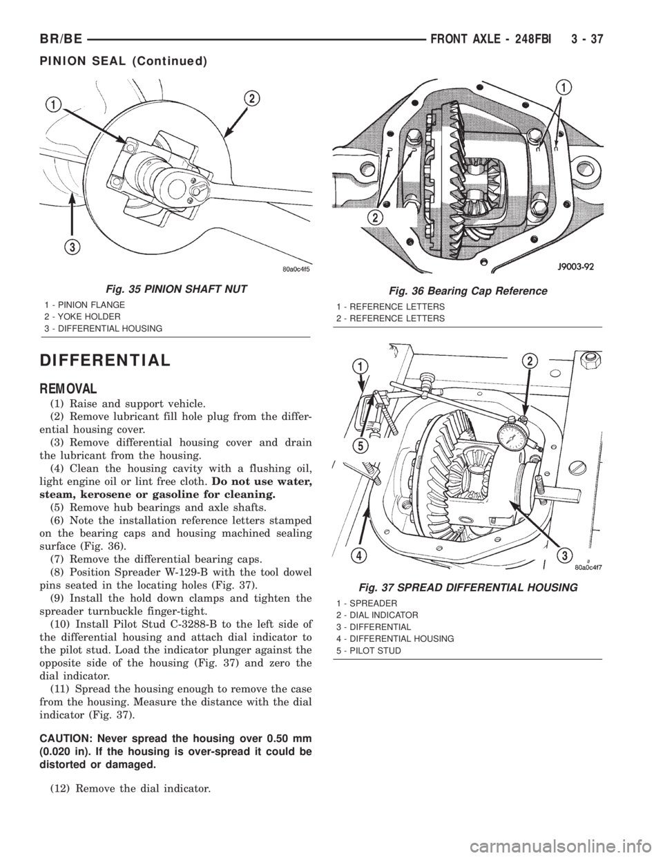
surface (Fig. 36).
(7) Remove the differential bearing caps.
(8) Position Spreader W-129-B with the tool dowel
pins seated in the locating holes (Fig. 37).
(9) Install the hold down clamps and tighten the
spreader turnbuckle finger-tight.
(10) Install Pilot Stud C-3288-B to the left side of
the differential housing and attach dial indicator to
the pilot stud. Load the indicator plunger against the
opposite side of the housing (Fig. 37) and zero the
dial indicator.
(11) Spread the housing enough to remove the case
from the housing. Measure the distance with the dial
indicator (Fig. 37).
CAUTION: Never spread the housing over 0.50 mm
(0.020 in). If the housing is over-spread it could be
distorted or damaged.
(12) Remove the dial indicator.
Fig. 35 PINION SHAFT NUT
1 - PINION FLANGE
2 - YOKE HOLDER
3 - DIFFERENTIAL HOUSING
Fig. 36 Bearing Cap Reference
1 - REFERENCE LETTERS
2 - REFERENCE LETTERS
Fig. 37 SPREAD DIFFERENTIAL HOUSING
1 - SPREADER
2 - DIAL INDICATOR
3 - DIFFERENTIAL
4 - DIFFERENTIAL HOUSING
5 - PILOT STUD
BR/BEFRONT AXLE - 248FBI 3 - 37
PINION SEAL (Continued)
Page 97 of 2255

(9) Remove pinion gear from housing (Fig. 49).
(10) Remove pinion seal with a pry bar or screw
mounted slide hammer.
(11) Remove oil slinger and front pinion bearing.
(12) Remove front pinion bearing cup with Driver
D-158 and Handle C-4171 (Fig. 50).(13) Remove rear bearing cup with remover D-162
and Handle C-4171 (Fig. 51).
(14) Remove collapsible preload spacer (Fig. 52).
Fig. 50 FRONT PINION BEARING CUP
1 - REMOVER
2 - HANDLE
Fig. 49 PINION GEAR REMOVAL
1 - RAWHIDE HAMMER
Fig. 51 REAR PINION BEARING CUP
1 - DRIVER
2 - HANDLE
Fig. 52 COLLAPSIBLE SPACER
1 - COLLAPSIBLE SPACER
2 - SHOULDER
3 - PINION GEAR
4 - OIL SLINGER
5 - REAR BEARING
3 - 42 FRONT AXLE - 248FBIBR/BE
PINION GEAR/RING GEAR (Continued)
Page 98 of 2255
(15) Remove rear pinion bearing from pinion with
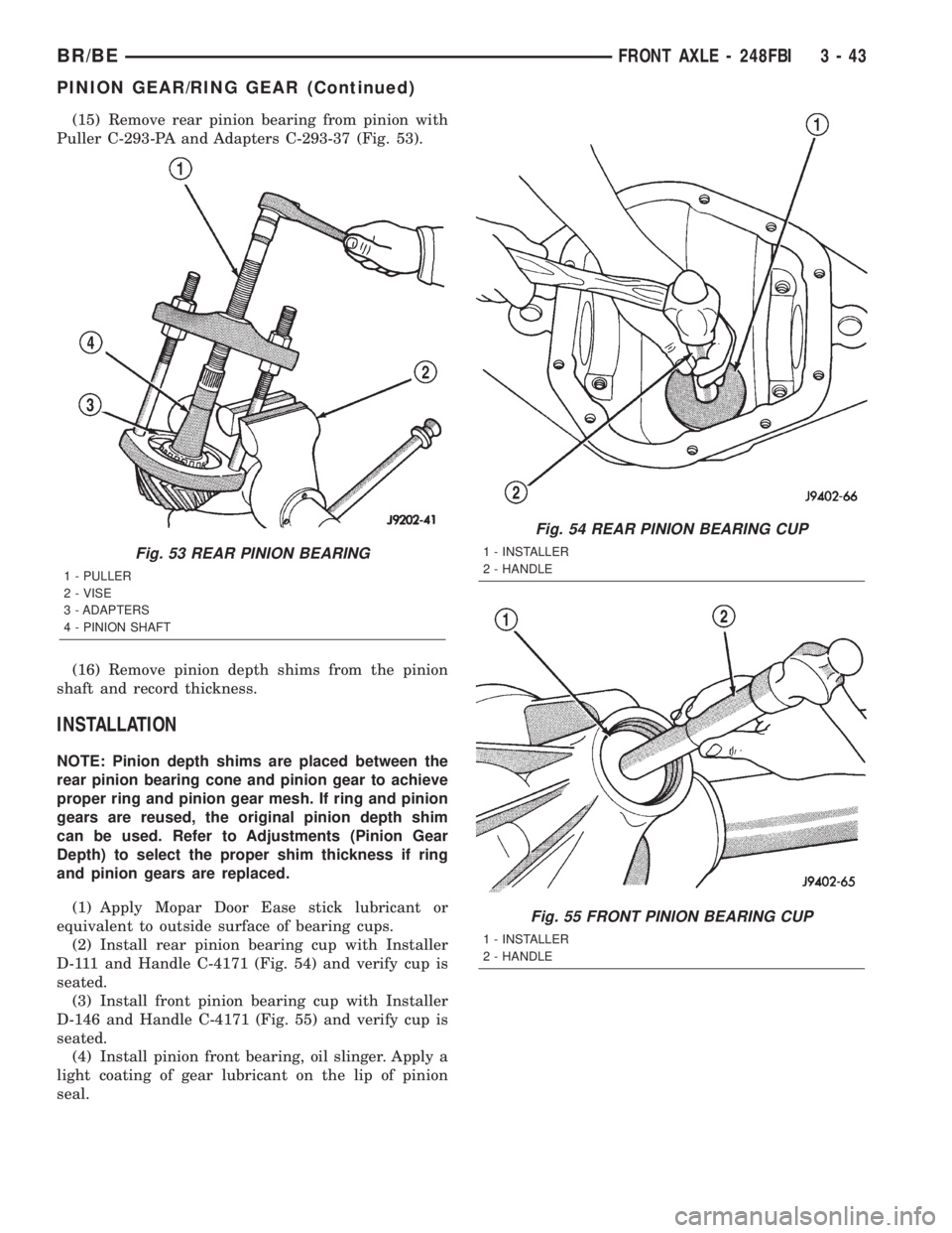
Puller C-293-PA and Adapters C-293-37 (Fig. 53).
(16) Remove pinion depth shims from the pinion
shaft and record thickness.
INSTALLATION
NOTE: Pinion depth shims are placed between the
rear pinion bearing cone and pinion gear to achieve
proper ring and pinion gear mesh. If ring and pinion
gears are reused, the original pinion depth shim
can be used. Refer to Adjustments (Pinion Gear
Depth) to select the proper shim thickness if ring
and pinion gears are replaced.
(1) Apply Mopar Door Ease stick lubricant or
equivalent to outside surface of bearing cups.
(2) Install rear pinion bearing cup with Installer
D-111 and Handle C-4171 (Fig. 54) and verify cup is
seated.
(3) Install front pinion bearing cup with Installer
D-146 and Handle C-4171 (Fig. 55) and verify cup is
seated.
(4) Install pinion front bearing, oil slinger. Apply a
light coating of gear lubricant on the lip of pinion
seal.
Fig. 53 REAR PINION BEARING
1 - PULLER
2 - VISE
3 - ADAPTERS
4 - PINION SHAFT
Fig. 54 REAR PINION BEARING CUP
1 - INSTALLER
2 - HANDLE
Fig. 55 FRONT PINION BEARING CUP
1 - INSTALLER
2 - HANDLE
BR/BEFRONT AXLE - 248FBI 3 - 43
PINION GEAR/RING GEAR (Continued)
Page 99 of 2255
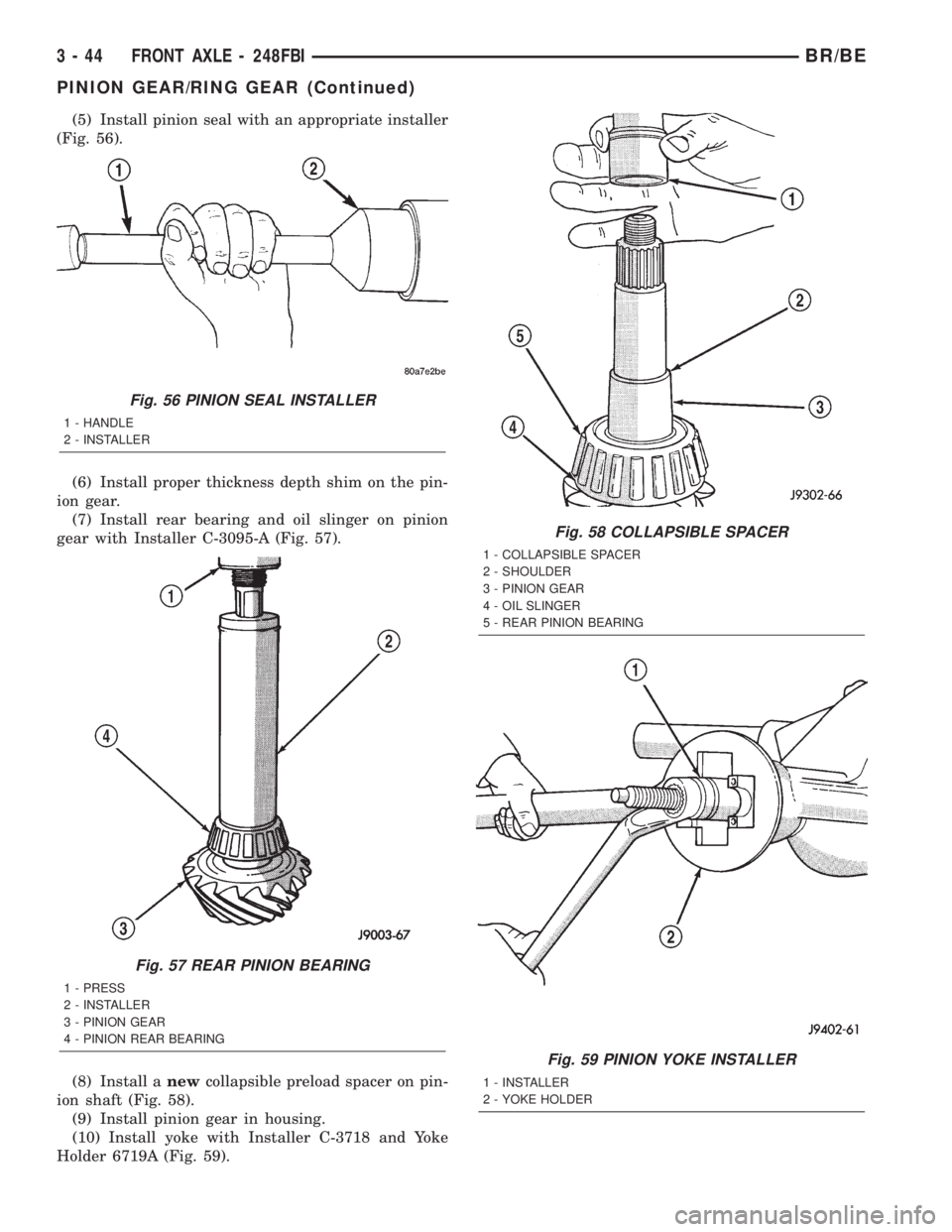
(5) Install pinion seal with an appropriate installer
(Fig. 56).
(6) Install proper thickness depth shim on the pin-
ion gear.
(7) Install rear bearing and oil slinger on pinion
gear with Installer C-3095-A (Fig. 57).
(8) Install anewcollapsible preload spacer on pin-
ion shaft (Fig. 58).
(9) Install pinion gear in housing.
(10) Install yoke with Installer C-3718 and Yoke
Holder 6719A (Fig. 59).
Fig. 56 PINION SEAL INSTALLER
1 - HANDLE
2 - INSTALLER
Fig. 57 REAR PINION BEARING
1 - PRESS
2 - INSTALLER
3 - PINION GEAR
4 - PINION REAR BEARING
Fig. 58 COLLAPSIBLE SPACER
1 - COLLAPSIBLE SPACER
2 - SHOULDER
3 - PINION GEAR
4 - OIL SLINGER
5 - REAR PINION BEARING
Fig. 59 PINION YOKE INSTALLER
1 - INSTALLER
2 - YOKE HOLDER
3 - 44 FRONT AXLE - 248FBIBR/BE
PINION GEAR/RING GEAR (Continued)
Page 106 of 2255

REMOVAL
(1) Raise and support the vehicle.
(2) Position an axle lift under the axle and secure
it to the axle.
(3) Remove the wheels and tires.
(4) Remove RWAL sensor from the differential
housing, if necessary.
(5) Remove brake hose from the axle junction
block.
(6) Disconnect parking brake cables and cable
brackets.
(7) Remove vent hose from the axle shaft tube.
(8) Mark propeller shaft and yoke for installation
alignment reference.
(9) Remove propeller shaft.
(10) Remove shock absorbers from the axle brack-
ets.
(11) Remove spring clamps and spring brackets.
(12) Remove axle from the vehicle.
INSTALLATION
(1) Raise axle with lift and align to the leaf spring
centering bolts.
(2) Install spring clamps and spring brackets.
(3) Install shock absorbers and tighten to specifica-
tions.
(4) Install RWAL sensor to the differential hous-
ing, if necessary.
(5) Install parking brake cables and cable brackets
(6) Install brake hose to the axle junction block.
(7) Install axle vent hose.
(8) Install propeller shaft with reference marks
aligned.
(9) Install wheels and tires assemblies.
(10) Add gear lubricant, if necessary.
(11) Remove lift from the axle and lower the vehi-
cle.
ADJUSTMENTS
Ring and pinion gears are supplied as matched
sets only. The identifying numbers for the ring and
pinion gear are etched into the face of each gear (Fig.
4). A plus (+) number, minus (±) number or zero (0) is
etched into the face of the pinion gear. This number
is the amount (in thousandths of an inch) the depth
varies from the standard depth setting of a pinion
etched with a (0). The standard setting from the cen-
ter line of the ring gear to the back face of the pinion
is 127 mm (5.00 in.). The standard depth provides
the best gear tooth contact pattern. Refer to Back-
lash and Contact Pattern in this section for addi-
tional information.
Compensation for pinion depth variance is
achieved with a select shim. The shims are placed
between the rear pinion bearing and the pinion gear
head (Fig. 5).If a new gear set is being installed, note the depth
variance etched into both the original and replace-
ment pinion. Add or subtract this number from the
thickness of the original depth shim/oil slinger to
compensate for the difference in the depth variances.
Refer to the Depth Variance chart.
Note where Old and New Pinion Marking columns
intersect. Intersecting figure represents plus or
minus the amount needed.
Fig. 4 PINION GEAR ID NUMBERS
1 - PRODUCTION NUMBERS
2 - PINION GEAR DEPTH VARIANCE
3 - GEAR MATCHING NUMBER
Fig. 5 SHIM LOCATIONS
1 - PINION GEAR DEPTH SHIM
2 - DIFFERENTIAL BEARING SHIM
BR/BEREAR AXLE - 248RBI 3 - 51
REAR AXLE - 248RBI (Continued)
Page 119 of 2255
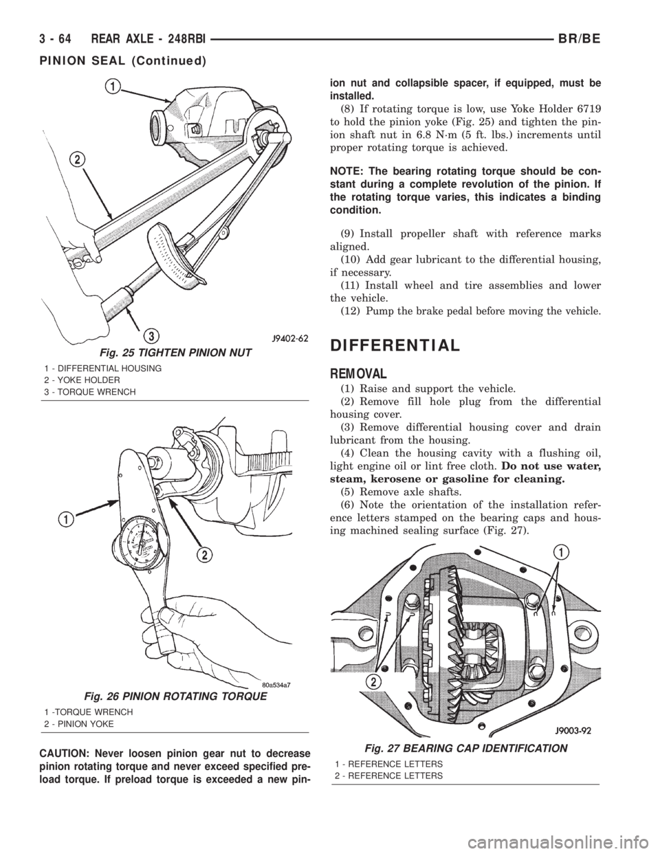
CAUTION: Never loosen pinion gear nut to decrease
pinion rotating torque and never exceed specified pre-
load torque. If preload torque is exceeded a new pin-ion nut and collapsible spacer, if equipped, must be
installed.
(8) If rotating torque is low, use Yoke Holder 6719
to hold the pinion yoke (Fig. 25) and tighten the pin-
ion shaft nut in 6.8 N´m (5 ft. lbs.) increments until
proper rotating torque is achieved.
NOTE: The bearing rotating torque should be con-
stant during a complete revolution of the pinion. If
the rotating torque varies, this indicates a binding
condition.
(9) Install propeller shaft with reference marks
aligned.
(10) Add gear lubricant to the differential housing,
if necessary.
(11) Install wheel and tire assemblies and lower
the vehicle.
(12)
Pump the brake pedal before moving the vehicle.
DIFFERENTIAL
REMOVAL
(1) Raise and support the vehicle.
(2) Remove fill hole plug from the differential
housing cover.
(3) Remove differential housing cover and drain
lubricant from the housing.
(4) Clean the housing cavity with a flushing oil,
light engine oil or lint free cloth.Do not use water,
steam, kerosene or gasoline for cleaning.
(5) Remove axle shafts.
(6) Note the orientation of the installation refer-
ence letters stamped on the bearing caps and hous-
ing machined sealing surface (Fig. 27).
Fig. 25 TIGHTEN PINION NUT
1 - DIFFERENTIAL HOUSING
2 - YOKE HOLDER
3 - TORQUE WRENCH
Fig. 26 PINION ROTATING TORQUE
1 -TORQUE WRENCH
2 - PINION YOKE
Fig. 27 BEARING CAP IDENTIFICATION
1 - REFERENCE LETTERS
2 - REFERENCE LETTERS
3 - 64 REAR AXLE - 248RBIBR/BE
PINION SEAL (Continued)