2002 DODGE RAM fuel type
[x] Cancel search: fuel typePage 1374 of 2255
(13) Use T-bar type puller (Fig. 37) to separate
injection pump gear from injection pump shaft.
Attach two M8 X 1.24 MM (metric) screws through
puller and into two threaded holes supplied in pump
gear. Pull injection pump gear forward until it loos-
ens from injection pump shaft.Pull on gear only
enough to loosen it from injection pump shaft.
Pulling gear too far may cause damage or
breakage to gear cover.(14) Remove 2 rear/lower pump bracket bolts (Fig.
38).
(15) Remove 4 injection pump-to-gear housing
mounting nuts (Fig. 39).
(16) Remove injection pump from gear housing.
Take care not to nick injection pump shaft on
aluminum gear housing when removing pump.
Also be very careful not to drop pump keyway
(Fig. 41) into gear housing.
CAUTION: Whenever the fuel injection pump is
removed from the engine, the pump drive gear is
laying loose on the camshaft drive gear. Never
attempt to crank or rotate the engine with the pump
removed from the engine. Serious damage will
occur.
INSTALLATION
(1) Inspect pump mounting surfaces at pump and
mounting flange for nicks, cuts or damage. Inspect
o-ring surfaces for nicks, cuts or damage.
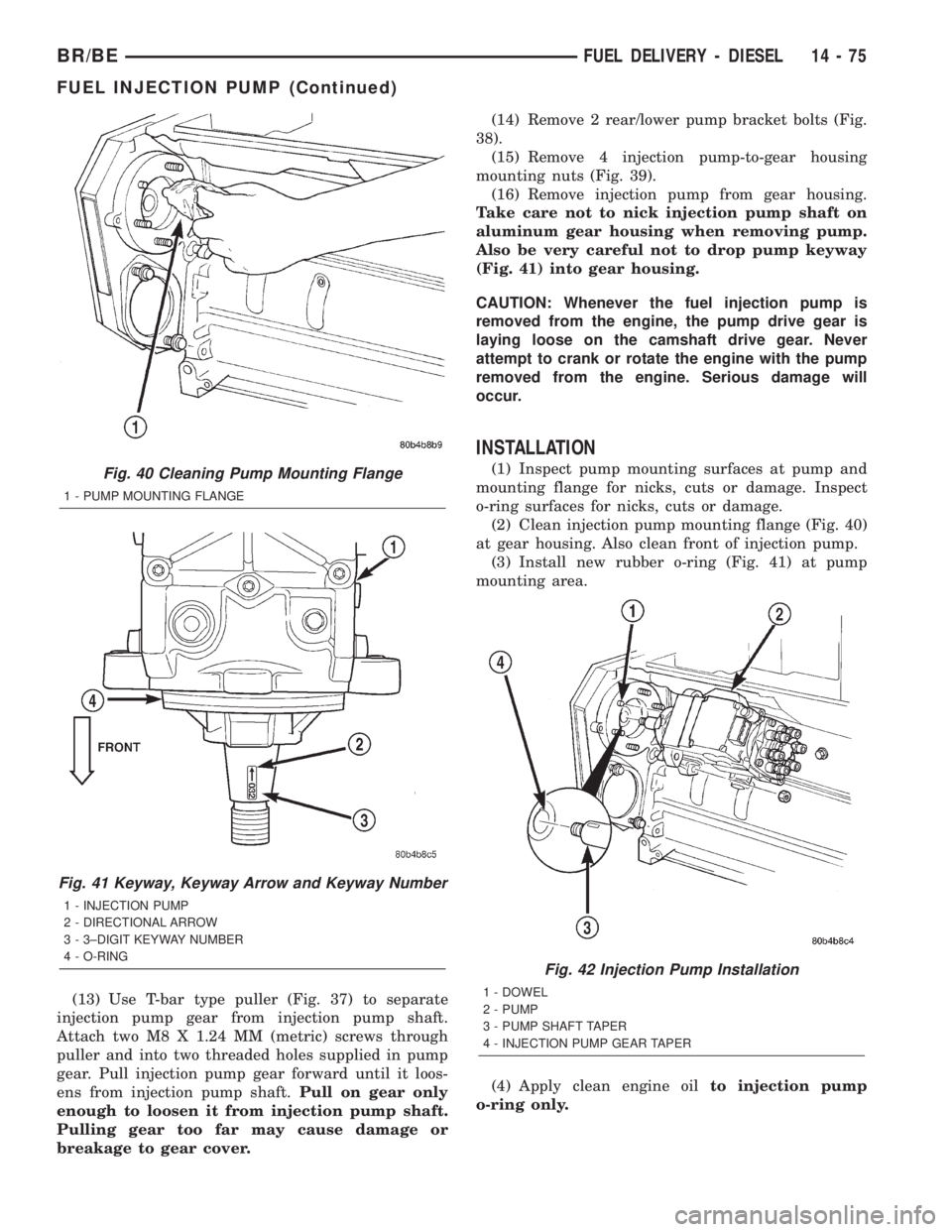
(2) Clean injection pump mounting flange (Fig. 40)
at gear housing. Also clean front of injection pump.
(3) Install new rubber o-ring (Fig. 41) at pump
mounting area.
(4) Apply clean engine oilto injection pump
o-ring only.Fig. 40 Cleaning Pump Mounting Flange
1 - PUMP MOUNTING FLANGE
Fig. 41 Keyway, Keyway Arrow and Keyway Number
1 - INJECTION PUMP
2 - DIRECTIONAL ARROW
3 - 3±DIGIT KEYWAY NUMBER
4 - O-RING
Fig. 42 Injection Pump Installation
1 - DOWEL
2 - PUMP
3 - PUMP SHAFT TAPER
4 - INJECTION PUMP GEAR TAPER
BR/BEFUEL DELIVERY - DIESEL 14 - 75
FUEL INJECTION PUMP (Continued)
Page 1375 of 2255
The machined tapers on both injection pump
shaft and injection pump gear (Fig. 42) must be
absolutely dry, clean and free of any dirt or oil
film. This will ensure proper gear-to-shaft tight-
ening.
(5) Clean pump gear and pump shaft at machined
tapers (Fig. 42) with an evaporative type cleaner
such as brake cleaner.
Keyway Installation:
(6) The pump/gear keyway has an arrow and a
3±digit number stamped at top edge (Fig. 41). Posi-
tion keyway into pump shaft witharrow pointed to
rear of pump.Also be sure 3±digit number stamped
to top of keyway is same as 3±digit number stamped
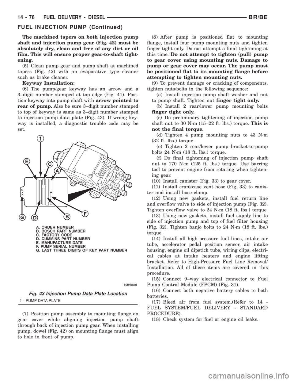
to injection pump data plate (Fig. 43). If wrong key-
way is installed, a diagnostic trouble code may be
set.
(7) Position pump assembly to mounting flange on
gear cover while aligning injection pump shaft
through back of injection pump gear. When installing
pump, dowel (Fig. 42) on mounting flange must align
to hole in front of pump.(8) After pump is positioned flat to mounting
flange, install four pump mounting nuts and tighten
finger tight only. Do not attempt a final tightening at
this time.Do not attempt to tighten (pull) pump
to gear cover using mounting nuts. Damage to
pump or gear cover may occur. The pump must
be positioned flat to its mounting flange before
attempting to tighten mounting nuts.
(9) To prevent damage or cracking of components,
tighten nuts/bolts in the following sequence:
(a) Install injection pump shaft washer and nut
to pump shaft. Tighten nutfinger tight only.
(b) Install 2 rear/lower pump mounting bolts
finger tight only.
(c) Do preliminary tightening of injection pump
shaft nut to 30 N´m (15±22 ft. lbs.) torque.This is
not the final torque.
(d) Tighten 4 pump mounting nuts to 43 N´m
(32 ft. lbs.) torque.
(e) Tighten 2 rear/lower pump bracket-to-pump
bolts 24 N´m (18 ft. lbs.) torque.
(f) Do final tightening of injection pump shaft
nut to 170 N´m (125 ft. lbs.) torque. Use barring
tool to prevent engine from rotating when tighten-
ing gear.
(10) Install canister (Fig. 33) to gear cover.
(11) Install crankcase vent hose (Fig. 33) to canis-
ter and install hose clamp.
(12) Using new gaskets, install fuel return line
and overflow valve to side of injection pump (Fig. 32).
Tighten overflow valve to 24 N´m (18 ft. lbs.) torque.
(13) Using new gaskets, install fuel supply line to
side of injection pump and top of fuel filter housing
(Fig. 32). Tighten banjo bolts to 24 N´m (18 ft. lbs.)
torque.
(14) Install all high-pressure fuel lines, intake air
tube, accelerator pedal position sensor, air intake
housing, engine oil dipstick tube, wiring clips, electri-
cal cables at intake heaters and engine lifting
bracket. Refer to High-Pressure Fuel Line Removal/
Installation. All of these items are covered in this
procedure.
(15) Connect 9±way electrical connector to Fuel
Pump Control Module (FPCM) (Fig. 31).
(16) Connect both negative battery cables to both
batteries.
(17) Bleed air from fuel system.(Refer to 14 -
FUEL SYSTEM/FUEL DELIVERY - STANDARD
PROCEDURE).
(18) Check system for fuel or engine oil leaks.
Fig. 43 Injection Pump Data Plate Location
1 - PUMP DATA PLATE
14 - 76 FUEL DELIVERY - DIESELBR/BE
FUEL INJECTION PUMP (Continued)
Page 1382 of 2255
REMOVAL
(1) Drain and remove fuel tank. Refer to Fuel
Tank Removal/Installation.
(2) Thoroughly clean area around tank module at
top of tank.
(3) The plastic fuel tank module locknut is
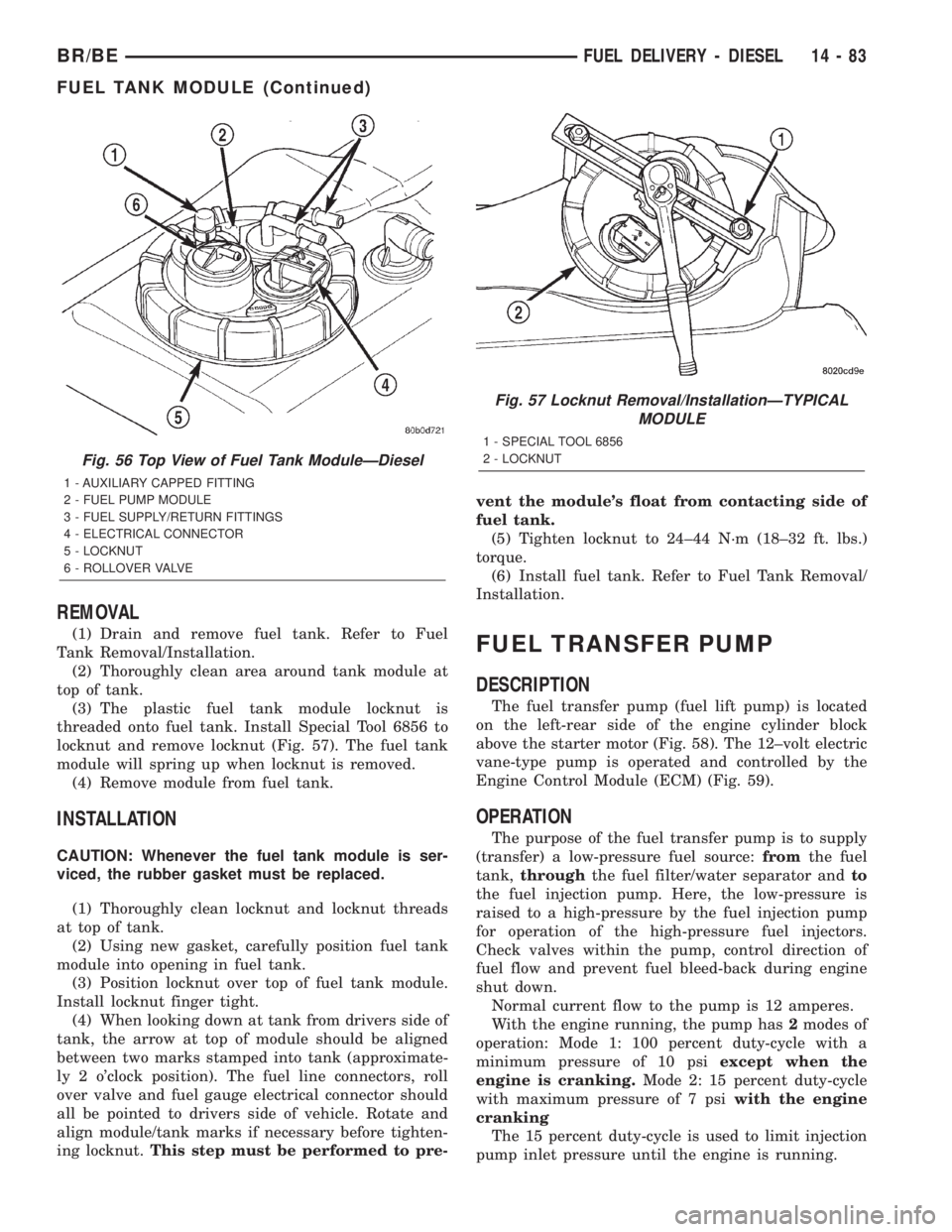
threaded onto fuel tank. Install Special Tool 6856 to
locknut and remove locknut (Fig. 57). The fuel tank
module will spring up when locknut is removed.
(4) Remove module from fuel tank.
INSTALLATION
CAUTION: Whenever the fuel tank module is ser-
viced, the rubber gasket must be replaced.
(1) Thoroughly clean locknut and locknut threads
at top of tank.
(2) Using new gasket, carefully position fuel tank
module into opening in fuel tank.
(3) Position locknut over top of fuel tank module.
Install locknut finger tight.
(4) When looking down at tank from drivers side of
tank, the arrow at top of module should be aligned
between two marks stamped into tank (approximate-
ly 2 o'clock position). The fuel line connectors, roll
over valve and fuel gauge electrical connector should
all be pointed to drivers side of vehicle. Rotate and
align module/tank marks if necessary before tighten-
ing locknut.This step must be performed to pre-vent the module's float from contacting side of
fuel tank.
(5) Tighten locknut to 24±44 N´m (18±32 ft. lbs.)
torque.
(6) Install fuel tank. Refer to Fuel Tank Removal/
Installation.
FUEL TRANSFER PUMP
DESCRIPTION
The fuel transfer pump (fuel lift pump) is located
on the left-rear side of the engine cylinder block
above the starter motor (Fig. 58). The 12±volt electric
vane-type pump is operated and controlled by the
Engine Control Module (ECM) (Fig. 59).
OPERATION
The purpose of the fuel transfer pump is to supply
(transfer) a low-pressure fuel source:fromthe fuel
tank,throughthe fuel filter/water separator andto
the fuel injection pump. Here, the low-pressure is
raised to a high-pressure by the fuel injection pump
for operation of the high-pressure fuel injectors.
Check valves within the pump, control direction of
fuel flow and prevent fuel bleed-back during engine
shut down.
Normal current flow to the pump is 12 amperes.
With the engine running, the pump has2modes of
operation: Mode 1: 100 percent duty-cycle with a
minimum pressure of 10 psiexcept when the
engine is cranking.Mode 2: 15 percent duty-cycle
with maximum pressure of 7 psiwith the engine
cranking
The 15 percent duty-cycle is used to limit injection
pump inlet pressure until the engine is running.
Fig. 56 Top View of Fuel Tank ModuleÐDiesel
1 - AUXILIARY CAPPED FITTING
2 - FUEL PUMP MODULE
3 - FUEL SUPPLY/RETURN FITTINGS
4 - ELECTRICAL CONNECTOR
5 - LOCKNUT
6 - ROLLOVER VALVE
Fig. 57 Locknut Removal/InstallationÐTYPICAL
MODULE
1 - SPECIAL TOOL 6856
2 - LOCKNUT
BR/BEFUEL DELIVERY - DIESEL 14 - 83
FUEL TANK MODULE (Continued)
Page 1397 of 2255
OPERATION
High-pressure fuel is supplied from the injection
pump, through a high-pressure fuel line, through a
steel connector and into the fuel injector. When fuel
pressure rises to approximately 31,026 kPa (4,500
psi), the needle valve spring tension is overcome. The
needle valve rises and fuel flows through the spray
holes in the nozzle tip into the combustion chamber.
The pressure required to lift the needle valve is the
nozzle opening pressure. This is sometimes referred
to as the ªpopº pressure setting.
Each fuel injector is connected to each high-pres-
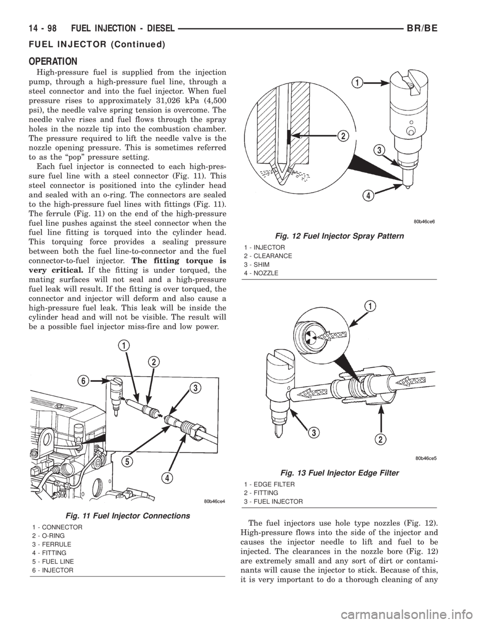
sure fuel line with a steel connector (Fig. 11). This
steel connector is positioned into the cylinder head
and sealed with an o-ring. The connectors are sealed
to the high-pressure fuel lines with fittings (Fig. 11).
The ferrule (Fig. 11) on the end of the high-pressure
fuel line pushes against the steel connector when the
fuel line fitting is torqued into the cylinder head.
This torquing force provides a sealing pressure
between both the fuel line-to-connector and the fuel
connector-to-fuel injector.The fitting torque is
very critical.If the fitting is under torqued, the
mating surfaces will not seal and a high-pressure
fuel leak will result. If the fitting is over torqued, the
connector and injector will deform and also cause a
high-pressure fuel leak. This leak will be inside the
cylinder head and will not be visible. The result will
be a possible fuel injector miss-fire and low power.
The fuel injectors use hole type nozzles (Fig. 12).
High-pressure flows into the side of the injector and
causes the injector needle to lift and fuel to be
injected. The clearances in the nozzle bore (Fig. 12)
are extremely small and any sort of dirt or contami-
nants will cause the injector to stick. Because of this,
it is very important to do a thorough cleaning of any
Fig. 11 Fuel Injector Connections
1 - CONNECTOR
2 - O-RING
3 - FERRULE
4 - FITTING
5 - FUEL LINE
6 - INJECTOR
Fig. 12 Fuel Injector Spray Pattern
1 - INJECTOR
2 - CLEARANCE
3 - SHIM
4 - NOZZLE
Fig. 13 Fuel Injector Edge Filter
1 - EDGE FILTER
2 - FITTING
3 - FUEL INJECTOR
14 - 98 FUEL INJECTION - DIESELBR/BE
FUEL INJECTOR (Continued)
Page 1584 of 2255
(16) Install crankshaft position sensor. (Refer to 14
- FUEL SYSTEM/FUEL INJECTION/CRANKSHAFT
POSITION SENSOR - INSTALLATION)
(17) Install new plastic retainer grommet on any
shift linkage rod or lever that was disconnected.
Grommets should not be reused. Use pry tool to
remove rod from grommet and cut away old grom-
met. Use pliers to snap new grommet into lever and
to snap rod into grommet at assembly.
(18) Connect gearshift and throttle cable to trans-
mission.
(19) Connect wires to park/neutral position switch,
transmission solenoid(s) and oxygen sensor. Be sure
transmission harnesses are properly routed.
CAUTION: It is essential that correct length bolts be
used to attach the converter to the driveplate. Bolts
that are too long will damage the clutch surface
inside the converter.
(20) Install torque converter-to-driveplate bolts.
On models with 10.75 in. converter, tighten bolts to31 N´m (270 in. lbs.). On models with 12.2 in. con-
verter, tighten bolts to 47 N´m (35 ft. lbs.).
(21) Install converter housing access cover.
(22) Install starter motor and cooler line bracket.
(Refer to 8 - ELECTRICAL/STARTING/STARTER
MOTOR - INSTALLATION)
(23) Connect cooler lines to transmission.
(24) Install transmission fill tube. Install new seal
on tube before installation.
(25) Install exhaust components.
(26) Align and connect propeller shaft. (Refer to 3 -
DIFFERENTIAL & DRIVELINE/PROPELLER
SHAFT/PROPELLER SHAFT - INSTALLATION)
(27) Adjust gearshift linkage and throttle valve
cable if necessary.
(28) Lower vehicle.
(29) Fill transmission with MopartATF +4, type
9602, Automatic Transmission fluid.
BR/BEAUTOMATIC TRANSMISSION - 46RE 21 - 131
AUTOMATIC TRANSMISSION - 46RE (Continued)
Page 1754 of 2255
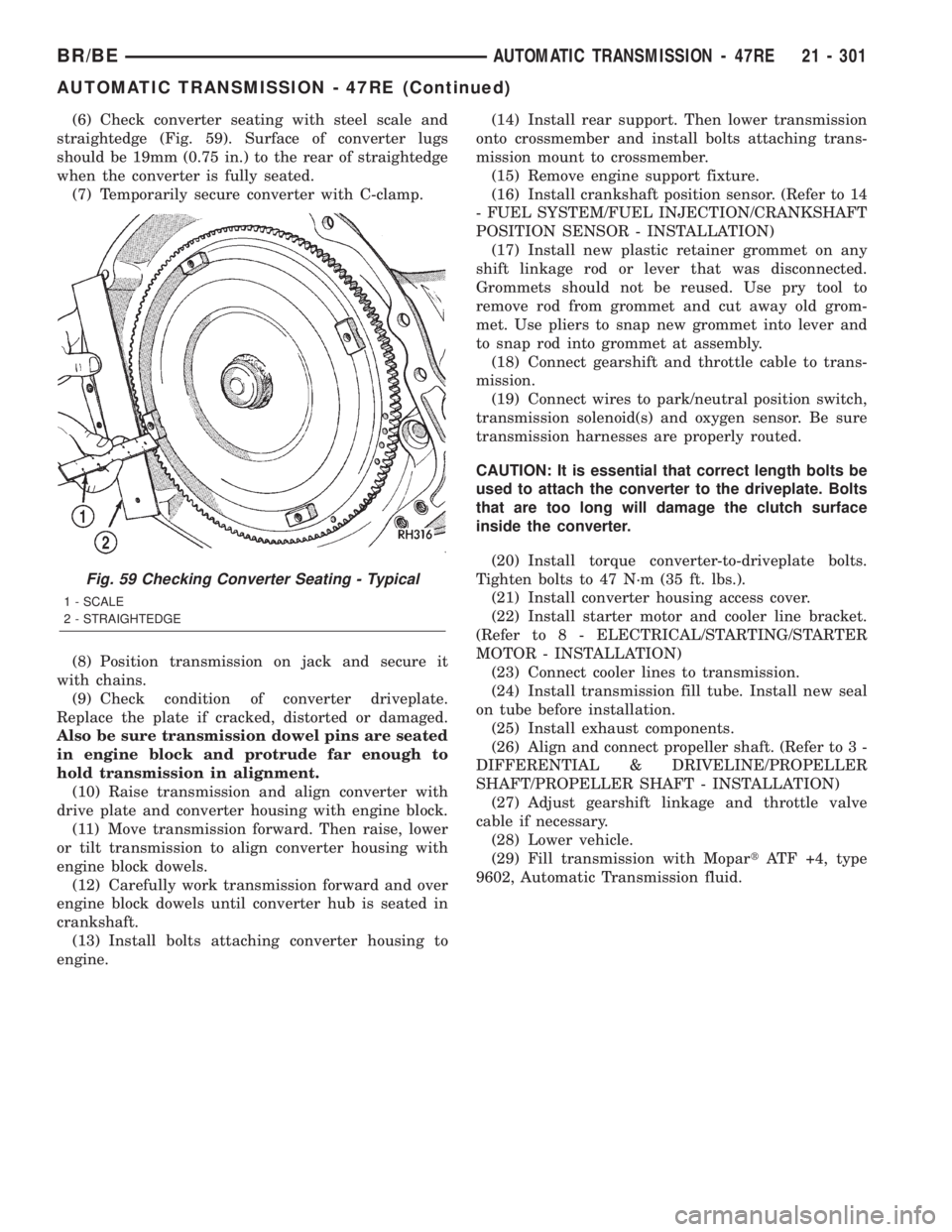
(6) Check converter seating with steel scale and
straightedge (Fig. 59). Surface of converter lugs
should be 19mm (0.75 in.) to the rear of straightedge
when the converter is fully seated.
(7) Temporarily secure converter with C-clamp.
(8) Position transmission on jack and secure it
with chains.
(9) Check condition of converter driveplate.
Replace the plate if cracked, distorted or damaged.
Also be sure transmission dowel pins are seated
in engine block and protrude far enough to
hold transmission in alignment.
(10) Raise transmission and align converter with
drive plate and converter housing with engine block.
(11) Move transmission forward. Then raise, lower
or tilt transmission to align converter housing with
engine block dowels.
(12) Carefully work transmission forward and over
engine block dowels until converter hub is seated in
crankshaft.
(13) Install bolts attaching converter housing to
engine.(14) Install rear support. Then lower transmission
onto crossmember and install bolts attaching trans-
mission mount to crossmember.
(15) Remove engine support fixture.
(16) Install crankshaft position sensor. (Refer to 14
- FUEL SYSTEM/FUEL INJECTION/CRANKSHAFT
POSITION SENSOR - INSTALLATION)
(17) Install new plastic retainer grommet on any
shift linkage rod or lever that was disconnected.
Grommets should not be reused. Use pry tool to
remove rod from grommet and cut away old grom-
met. Use pliers to snap new grommet into lever and
to snap rod into grommet at assembly.
(18) Connect gearshift and throttle cable to trans-
mission.
(19) Connect wires to park/neutral position switch,
transmission solenoid(s) and oxygen sensor. Be sure
transmission harnesses are properly routed.
CAUTION: It is essential that correct length bolts be
used to attach the converter to the driveplate. Bolts
that are too long will damage the clutch surface
inside the converter.
(20) Install torque converter-to-driveplate bolts.
Tighten bolts to 47 N´m (35 ft. lbs.).
(21) Install converter housing access cover.
(22) Install starter motor and cooler line bracket.
(Refer to 8 - ELECTRICAL/STARTING/STARTER
MOTOR - INSTALLATION)
(23) Connect cooler lines to transmission.
(24) Install transmission fill tube. Install new seal
on tube before installation.
(25) Install exhaust components.
(26) Align and connect propeller shaft. (Refer to 3 -
DIFFERENTIAL & DRIVELINE/PROPELLER
SHAFT/PROPELLER SHAFT - INSTALLATION)
(27) Adjust gearshift linkage and throttle valve
cable if necessary.
(28) Lower vehicle.
(29) Fill transmission with MopartATF +4, type
9602, Automatic Transmission fluid.
Fig. 59 Checking Converter Seating - Typical
1 - SCALE
2 - STRAIGHTEDGE
BR/BEAUTOMATIC TRANSMISSION - 47RE 21 - 301
AUTOMATIC TRANSMISSION - 47RE (Continued)
Page 2053 of 2255
EXTERIOR
TABLE OF CONTENTS
page page
EXTERIOR
DESCRIPTION.........................86
OPERATION...........................86
BODY SIDE MOLDINGS
REMOVAL.............................86
INSTALLATION.........................87
BODY STRIPES AND DECALS
REMOVAL.............................87
INSTALLATION.........................87
TAPE STRIPE
REMOVAL.............................88
INSTALLATION.........................89
EXTERIOR NAME PLATES
REMOVAL.............................89
INSTALLATION.........................89
COWL GRILLE
REMOVAL.............................90
INSTALLATION.........................90
ROOF JOINT MOLDING
REMOVAL.............................91
INSTALLATION.........................91
GRILLE
REMOVAL.............................91
INSTALLATION.........................91
GRILLE FRAME
REMOVAL.............................91
INSTALLATION.........................92
FRONT END SPLASH SHIELDS
REMOVAL.............................92
INSTALLATION.........................92LEFT FRONT FENDER
REMOVAL.............................93
INSTALLATION.........................93
RIGHT FRONT FENDER
REMOVAL.............................94
INSTALLATION.........................94
FUEL FILL DOOR
REMOVAL.............................95
INSTALLATION.........................95
REAR FENDER
REMOVAL.............................95
INSTALLATION.........................95
REAR SPLASH SHIELD
REMOVAL.............................96
INSTALLATION.........................96
REAR WHEELHOUSE LINER
REMOVAL.............................96
INSTALLATION.........................96
CARGO BOX
REMOVAL.............................97
INSTALLATION.........................97
SIDE VIEW MIRROR
REMOVAL.............................97
INSTALLATION.........................98
SIDE VIEW MIRROR - LOW MOUNTED
REMOVAL.............................98
INSTALLATION.........................98
SIDE VIEW MIRROR GLASS
REMOVAL.............................98
INSTALLATION.........................98
EXTERIOR
DESCRIPTION
Exterior sheet metal components make up the
exterior of the vehicle. Some exterior metal systems
are welded assemblies, such as doors and hoods.
Some exterior trim items are made of composite.
OPERATION
The exterior is finished in various metal stampings
and composite moldings. These assemblies give the
vehicle a finished appearance and protect the occu-
pants from the elements. Some components are part
of the energy absorbing system used to protect the
occupants in collisions. The exterior sheet metal is
repairable and adjustable for fit and finish. Welded
and bonded component systems are adjustable as asystem. Trim components made of composite are
stamped with the type of material used.
DaimlerChrysler uses various fasteners to retain
trim items. At times, it is not possible to remove trim
items without damaging the fastener. If it is not pos-
sible to remove an item without damaging a compo-
nent, cut or break the fasteners and use new ones
when installing the component.BODY SIDE MOLDINGS
REMOVAL
(1) Warm the effected stick-on molding and body
metal to approximately 38ÉC (100ÉF) using a suitable
heat lamp or heat gun.
(2) Pull stick-on molding from painted surface
(Fig. 1) and (Fig. 2).
23 - 86 EXTERIORBR/BE
Page 2198 of 2255
The catalyst monitor uses dual oxygen sensors
(O2S's) to monitor the efficiency of the converter. The
dual O2S's sensor strategy is based on the fact that
as a catalyst deteriorates, its oxygen storage capacity
and its efficiency are both reduced. By monitoring
the oxygen storage capacity of a catalyst, its effi-
ciency can be indirectly calculated. The upstream
O2S is used to detect the amount of oxygen in the
exhaust gas before the gas enters the catalytic con-
verter. The PCM calculates the A/F mixture from the
output of the O2S. A low voltage indicates high oxy-
gen content (lean mixture). A high voltage indicates a
low content of oxygen (rich mixture).
When the upstream O2S detects a lean condition,
there is an abundance of oxygen in the exhaust gas.
A functioning converter would store this oxygen so it
can use it for the oxidation of HC and CO. As the
converter absorbs the oxygen, there will be a lack of
oxygen downstream of the converter. The output of
the downstream O2S will indicate limited activity in
this condition.
As the converter loses the ability to store oxygen,
the condition can be detected from the behavior of
the downstream O2S. When the efficiency drops, no
chemical reaction takes place. This means the con-
centration of oxygen will be the same downstream as
upstream. The output voltage of the downstream
O2S copies the voltage of the upstream sensor. The
only difference is a time lag (seen by the PCM)
between the switching of the O2S's.
To monitor the system, the number of lean-to-rich
switches of upstream and downstream O2S's is
counted. The ratio of downstream switches to
upstream switches is used to determine whether the
catalyst is operating properly. An effective catalyst
will have fewer downstream switches than it has
upstream switches i.e., a ratio closer to zero. For a
totally ineffective catalyst, this ratio will be one-to-
one, indicating that no oxidation occurs in the device.
The system must be monitored so that when cata-
lyst efficiency deteriorates and exhaust emissions
increase to over the legal limit, the MIL will be illu-
minated.
DESCRIPTION - TRIP DEFINITION
The term ªTripº has different meanings depending
on what the circumstances are. If the MIL (Malfunc-
tion Indicator Lamp) is OFF, a Trip is defined as
when the Oxygen Sensor Monitor and the Catalyst
Monitor have been completed in the same drive cycle.
When any Emission DTC is set, the MIL on the
dash is turned ON. When the MIL is ON, it takes 3
good trips to turn the MIL OFF. In this case, it
depends on what type of DTC is set to know what a
ªTripº is.For the Fuel Monitor or Mis-Fire Monitor (contin-
uous monitor), the vehicle must be operated in the
ªSimilar Condition Windowº for a specified amount of
time to be considered a Good Trip.
If a Non-Contiuous OBDII Monitor fails twice in a
row and turns ON the MIL, re-running that monitor
which previously failed, on the next start-up and
passing the monitor, is considered to be a Good Trip.
These will include the following:
²Oxygen Sensor
²Catalyst Monitor
²Purge Flow Monitor
²Leak Detection Pump Monitor (if equipped)
²EGR Monitor (if equipped)
²Oxygen Sensor Heater Monitor
If any other Emission DTC is set (not an OBDII
Monitor), a Good Trip is considered to be when the
Oxygen Sensor Monitor and Catalyst Monitor have
been completed; or 2 Minutes of engine run time if
the Oxygen Sensor Monitor or Catalyst Monitor have
been stopped from running.
It can take up to 2 Failures in a row to turn on the
MIL. After the MIL is ON, it takes 3 Good Trips to
turn the MIL OFF. After the MIL is OFF, the PCM
will self-erase the DTC after 40 Warm-up cycles. A
Warm-up cycle is counted when the ECT (Engine
Coolant Temperature Sensor) has crossed 160ÉF and
has risen by at least 40ÉF since the engine has been
started.
DESCRIPTION - COMPONENT MONITORS -
GAS ENGINES
There are several components that will affect vehi-
cle emissions if they malfunction. If one of these com-
ponents malfunctions the Malfunction Indicator
Lamp (MIL) will illuminate.
Some of the component monitors are checking for
proper operation of the part. Electrically operated
components now have input (rationality) and output
(functionality) checks. Previously, a component like
the Throttle Position sensor (TPS) was checked by
the PCM for an open or shorted circuit. If one of
these conditions occurred, a DTC was set. Now there
is a check to ensure that the component is working.
This is done by watching for a TPS indication of a
greater or lesser throttle opening than MAP and
engine rpm indicate. In the case of the TPS, if engine
vacuum is high and engine rpm is 1600 or greater,
and the TPS indicates a large throttle opening, a
DTC will be set. The same applies to low vacuum if
the TPS indicates a small throttle opening.
All open/short circuit checks, or any component
that has an associated limp-in, will set a fault after 1
trip with the malfunction present. Components with-
out an associated limp-in will take two trips to illu-
minate the MIL.
BR/BEEMISSIONS CONTROL 25 - 19
EMISSIONS CONTROL (Continued)