2002 DODGE RAM fuel type
[x] Cancel search: fuel typePage 1311 of 2255
FUEL PUMP MODULE
DESCRIPTION
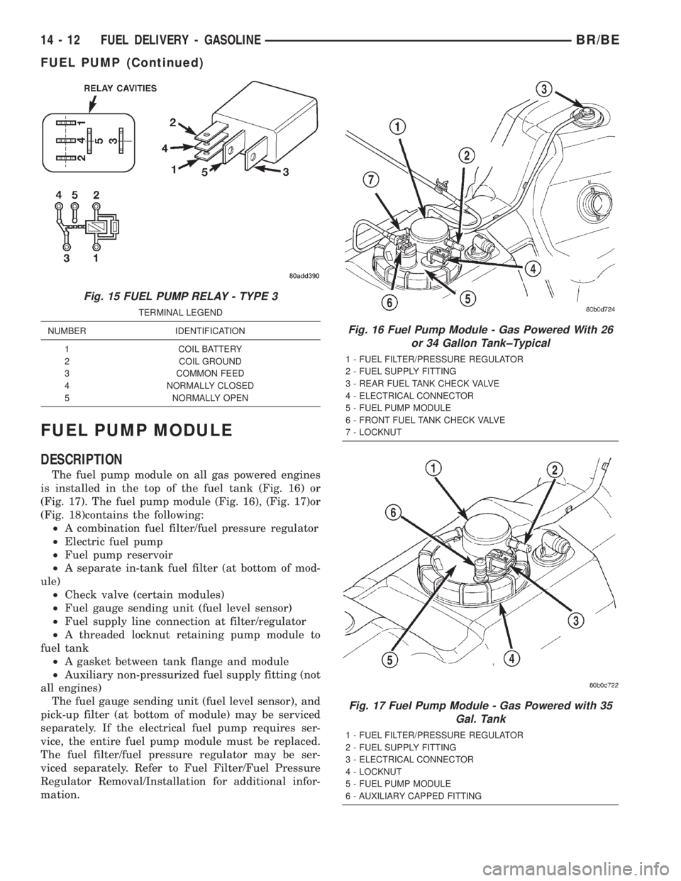
The fuel pump module on all gas powered engines
is installed in the top of the fuel tank (Fig. 16) or
(Fig. 17). The fuel pump module (Fig. 16), (Fig. 17)or
(Fig. 18)contains the following:
²A combination fuel filter/fuel pressure regulator
²Electric fuel pump
²Fuel pump reservoir
²A separate in-tank fuel filter (at bottom of mod-
ule)
²Check valve (certain modules)
²Fuel gauge sending unit (fuel level sensor)
²Fuel supply line connection at filter/regulator
²A threaded locknut retaining pump module to
fuel tank
²A gasket between tank flange and module
²Auxiliary non-pressurized fuel supply fitting (not
all engines)
The fuel gauge sending unit (fuel level sensor), and
pick-up filter (at bottom of module) may be serviced
separately. If the electrical fuel pump requires ser-
vice, the entire fuel pump module must be replaced.
The fuel filter/fuel pressure regulator may be ser-
viced separately. Refer to Fuel Filter/Fuel Pressure
Regulator Removal/Installation for additional infor-
mation.
Fig. 15 FUEL PUMP RELAY - TYPE 3
TERMINAL LEGEND
NUMBER IDENTIFICATION
1 COIL BATTERY
2 COIL GROUND
3 COMMON FEED
4 NORMALLY CLOSED
5 NORMALLY OPEN
Fig. 16 Fuel Pump Module - Gas Powered With 26
or 34 Gallon Tank±Typical
1 - FUEL FILTER/PRESSURE REGULATOR
2 - FUEL SUPPLY FITTING
3 - REAR FUEL TANK CHECK VALVE
4 - ELECTRICAL CONNECTOR
5 - FUEL PUMP MODULE
6 - FRONT FUEL TANK CHECK VALVE
7 - LOCKNUT
Fig. 17 Fuel Pump Module - Gas Powered with 35
Gal. Tank
1 - FUEL FILTER/PRESSURE REGULATOR
2 - FUEL SUPPLY FITTING
3 - ELECTRICAL CONNECTOR
4 - LOCKNUT
5 - FUEL PUMP MODULE
6 - AUXILIARY CAPPED FITTING
14 - 12 FUEL DELIVERY - GASOLINEBR/BE
FUEL PUMP (Continued)
Page 1323 of 2255
QUICK CONNECT FITTING
DESCRIPTION
Different types of quick-connect fittings are used to
attach various fuel system components, lines and
tubes. These are: a single-tab type, a two-tab type or
a plastic retainer ring type. Some are equipped with
safety latch clips. Some may require the use of a spe-
cial tool for disconnection and removal. Refer to
Quick-Connect Fittings Removal/Installation for more
information.
CAUTION: The interior components (o-rings, clips)
of quick-connect fittings are not serviced sepa-
rately, but new plastic spacers are available for
some types. If service parts are not available, do
not attempt to repair the damaged fitting or fuel line
(tube). If repair is necessary, replace the complete
fuel line (tube) assembly.
STANDARD PROCEDURE - QUICK-CONNECT
FITTINGS
Also refer to Fuel Tubes/Lines/Hoses and Clamps.
Different types of quick-connect fittings are used to
attach various fuel system components, lines and
tubes. These are: a single-tab type, a two-tab type or
a plastic retainer ring type. Safety latch clips are
used on certain components/lines. Certain fittings
may require use of a special tool for disconnection.
DISCONNECTING
WARNING: THE FUEL SYSTEM IS UNDER A CON-
STANT PRESSURE (EVEN WITH ENGINE OFF).
BEFORE SERVICING ANY FUEL SYSTEM HOSE,
FITTING OR LINE, FUEL SYSTEM PRESSURE MUST
BE RELEASED. REFER TO FUEL SYSTEM PRES-
SURE RELEASE PROCEDURE.
CAUTION: The interior components (o-rings, spac-
ers) of some types of quick-connect fitting are not
serviced separately. If service parts are not avail-
able, do not attempt to repair a damaged fitting or
fuel line. If repair is necessary, replace complete
fuel line assembly.(1) Perform fuel pressure release procedure. Refer
to Fuel Pressure Release Procedure.
(2) Disconnect negative battery cable from battery.
(3) Clean fitting of any foreign material before dis-
assembly.
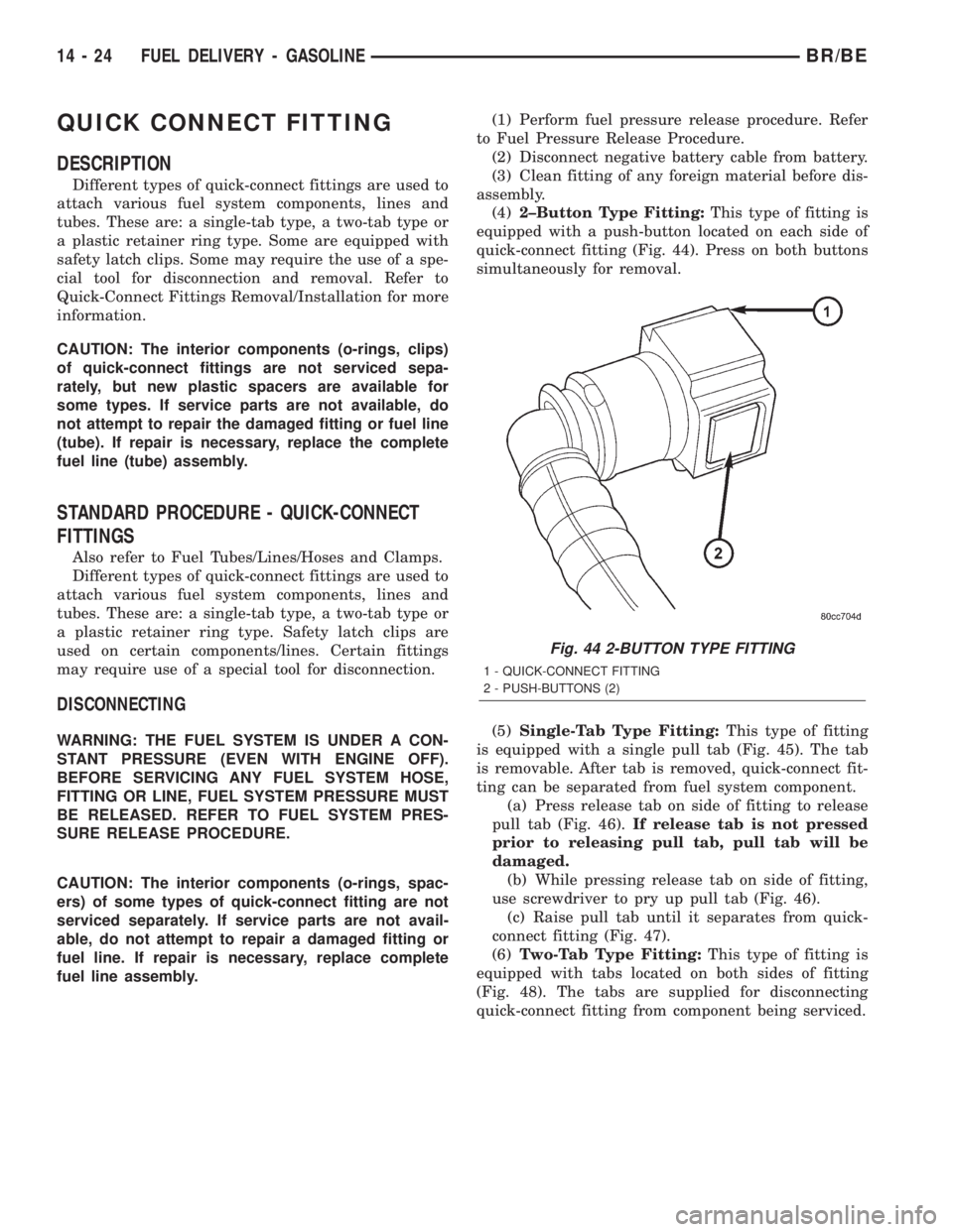
(4)2±Button Type Fitting:This type of fitting is
equipped with a push-button located on each side of
quick-connect fitting (Fig. 44). Press on both buttons
simultaneously for removal.
(5)Single-Tab Type Fitting:This type of fitting
is equipped with a single pull tab (Fig. 45). The tab
is removable. After tab is removed, quick-connect fit-
ting can be separated from fuel system component.
(a) Press release tab on side of fitting to release
pull tab (Fig. 46).If release tab is not pressed
prior to releasing pull tab, pull tab will be
damaged.
(b) While pressing release tab on side of fitting,
use screwdriver to pry up pull tab (Fig. 46).
(c) Raise pull tab until it separates from quick-
connect fitting (Fig. 47).
(6)Two-Tab Type Fitting:This type of fitting is
equipped with tabs located on both sides of fitting
(Fig. 48). The tabs are supplied for disconnecting
quick-connect fitting from component being serviced.
Fig. 44 2-BUTTON TYPE FITTING
1 - QUICK-CONNECT FITTING
2 - PUSH-BUTTONS (2)
14 - 24 FUEL DELIVERY - GASOLINEBR/BE
Page 1324 of 2255
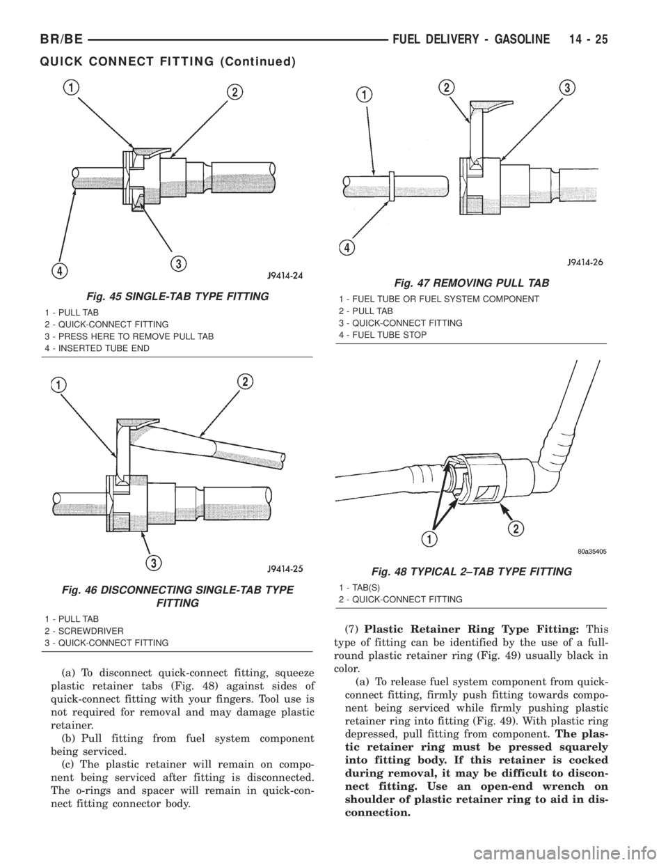
(a) To disconnect quick-connect fitting, squeeze
plastic retainer tabs (Fig. 48) against sides of
quick-connect fitting with your fingers. Tool use is
not required for removal and may damage plastic
retainer.
(b) Pull fitting from fuel system component
being serviced.
(c) The plastic retainer will remain on compo-
nent being serviced after fitting is disconnected.
The o-rings and spacer will remain in quick-con-
nect fitting connector body.(7)Plastic Retainer Ring Type Fitting:This
type of fitting can be identified by the use of a full-
round plastic retainer ring (Fig. 49) usually black in
color.
(a) To release fuel system component from quick-
connect fitting, firmly push fitting towards compo-
nent being serviced while firmly pushing plastic
retainer ring into fitting (Fig. 49). With plastic ring
depressed, pull fitting from component.The plas-
tic retainer ring must be pressed squarely
into fitting body. If this retainer is cocked
during removal, it may be difficult to discon-
nect fitting. Use an open-end wrench on
shoulder of plastic retainer ring to aid in dis-
connection.
Fig. 45 SINGLE-TAB TYPE FITTING
1 - PULL TAB
2 - QUICK-CONNECT FITTING
3 - PRESS HERE TO REMOVE PULL TAB
4 - INSERTED TUBE END
Fig. 46 DISCONNECTING SINGLE-TAB TYPE
FITTING
1 - PULL TAB
2 - SCREWDRIVER
3 - QUICK-CONNECT FITTING
Fig. 47 REMOVING PULL TAB
1 - FUEL TUBE OR FUEL SYSTEM COMPONENT
2 - PULL TAB
3 - QUICK-CONNECT FITTING
4 - FUEL TUBE STOP
Fig. 48 TYPICAL 2±TAB TYPE FITTING
1 - TAB(S)
2 - QUICK-CONNECT FITTING
BR/BEFUEL DELIVERY - GASOLINE 14 - 25
QUICK CONNECT FITTING (Continued)
Page 1325 of 2255
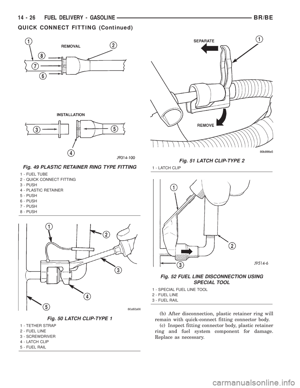
(b) After disconnection, plastic retainer ring will
remain with quick-connect fitting connector body.
(c) Inspect fitting connector body, plastic retainer
ring and fuel system component for damage.
Replace as necessary.
Fig. 49 PLASTIC RETAINER RING TYPE FITTING
1 - FUEL TUBE
2 - QUICK CONNECT FITTING
3 - PUSH
4 - PLASTIC RETAINER
5 - PUSH
6 - PUSH
7 - PUSH
8 - PUSH
Fig. 50 LATCH CLIP-TYPE 1
1 - TETHER STRAP
2 - FUEL LINE
3 - SCREWDRIVER
4 - LATCH CLIP
5 - FUEL RAIL
Fig. 51 LATCH CLIP-TYPE 2
1 - LATCH CLIP
Fig. 52 FUEL LINE DISCONNECTION USING
SPECIAL TOOL
1 - SPECIAL FUEL LINE TOOL
2 - FUEL LINE
3 - FUEL RAIL
14 - 26 FUEL DELIVERY - GASOLINEBR/BE
QUICK CONNECT FITTING (Continued)
Page 1326 of 2255
(8)Latch Clips:Depending on vehicle model and
engine, 2 different types of safety latch clips are used
(Fig. 50) or (Fig. 51). Type-1 is tethered to fuel line
and type-2 is not. A special tool will be necessary to
disconnect fuel line after latch clip is removed. The
latch clip may be used on certain fuel line/fuel rail
connection, or to join fuel lines together.
(a) Type 1: Pry up on latch clip with a screw-
driver (Fig. 50).
(b) Type 2: Separate and unlatch 2 small arms
on end of clip (Fig. 51) and swing away from fuel
line.
(c) Slide latch clip toward fuel rail while lifting
with screwdriver.
(d) Insert special fuel line removal tool (Snap-On
number FIH 9055-1 or equivalent) into fuel line
(Fig. 52). Use tool to release locking fingers in end
of line.
(e) With special tool still inserted, pull fuel line
from fuel rail.
(f) After disconnection, locking fingers will
remain within quick-connect fitting at end of fuel
line.
(9) Disconnect quick-connect fitting from fuel sys-
tem component being serviced.CONNECTING
(1) Inspect quick-connect fitting body and fuel sys-
tem component for damage. Replace as necessary.
(2) Prior to connecting quick-connect fitting to
component being serviced, check condition of fitting
and component. Clean parts with a lint-free cloth.
Lubricate with clean engine oil.
(3) Insert quick-connect fitting into fuel tube or
fuel system component until built-on stop on fuel
tube or component rests against back of fitting.
(4) Continue pushing until a click is felt.
(5) Single-tab type fitting: Push new tab down
until it locks into place in quick-connect fitting.
(6) Verify a locked condition by firmly pulling on
fuel tube and fitting (15-30 lbs.).
(7) Latch Clip Equipped: Install latch clip (snaps
into position).If latch clip will not fit, this indi-
cates fuel line is not properly installed to fuel
rail (or other fuel line). Recheck fuel line con-
nection.
(8) Connect negative cable to battery.
(9) Start engine and check for leaks.
BR/BEFUEL DELIVERY - GASOLINE 14 - 27
QUICK CONNECT FITTING (Continued)
Page 1345 of 2255

around 70ÉF, the resistance of the heating element is
approximately 4.5 ohms. As the sensor's temperature
increases, resistance in the heater element increases.
This allows the heater to maintain the optimum
operating temperature of approximately 930É-1100ÉF
(500É-600É C). Although the sensors operate the
same, there are physical differences, due to the envi-
ronment that they operate in, that keep them from
being interchangeable.
Maintaining correct sensor temperature at all
times allows the system to enter into closed loop
operation sooner. Also, it allows the system to remain
in closed loop operation during periods of extended
idle.
In Closed Loop operation, the PCM monitors cer-
tain O2 sensor input(s) along with other inputs, and
adjusts the injector pulse width accordingly. During
Open Loop operation, the PCM ignores the O2 sensor
input. The PCM adjusts injector pulse width based
on preprogrammed (fixed) values and inputs from
other sensors.
Upstream Sensors:Two upstream sensors are
used (1/1 and 2/1). The 1/1 sensor is the first sensor
to receive exhaust gases from the #1 cylinder. They
provide an input voltage to the PCM. The input tells
the PCM the oxygen content of the exhaust gas. The
PCM uses this information to fine tune fuel delivery
to maintain the correct oxygen content at the down-
stream oxygen sensors. The PCM will change the air/
fuel ratio until the upstream sensors input a voltage
that the PCM has determined will make the down-
stream sensors output (oxygen content) correct.
The upstream oxygen sensors also provide an input
to determine mini-catalyst efficiency. Main catalytic
convertor efficiency is not calculated with this pack-
age.
Downstream Sensors:Two downstream sensors
are used (1/2 and 2/2). The downstream sensors are
used to determine the correct air-fuel ratio. As the
oxygen content changes at the downstream sensor,
the PCM calculates how much air-fuel ratio change is
required. The PCM then looks at the upstream oxy-
gen sensor voltage, and changes fuel delivery until
the upstream sensor voltage changes enough to cor-
rect the downstream sensor voltage (oxygen content).
The downstream oxygen sensors also provide an
input to determine mini-catalyst efficiency. Main cat-
alytic convertor efficiency is not calculated with this
package.
Medium and Heavy Duty 8.0L V-10 Engine:
Four oxygen sensors are used (2 upstream, 1 pre-cat-
alyst and 1 post-catalyst). The upstream sensors (1/1
and 2/1) will fine-tune the air-fuel ratio through the
Powertrain Control Module (PCM). The pre-catalyst
(1/2) and post-catalyst (1/3) sensors will determine
catalytic convertor efficiency (efficiency of the maincatalytic convertor). This is also done through the
PCM.
Heavy Duty 5.9L Engine:Downstream sensors
are not used with this emissions package, meaning
catalytic convertor efficiency is not calculated with
this package. Two upstream sensors are used. The
left upstream sensor (1/1) will monitor cylinders 1, 3,
5 and 7. The right upstream sensor (2/1) will monitor
cylinders 2, 4, 6 and 8. The PCM monitors the oxy-
gen content of the sensors, and will fine-tune the air-
fuel ratio.
Engines equipped with either a downstream sen-
sor(s), or a post-catalytic sensor, will monitor cata-
lytic convertor efficiency. If efficiency is below
emission standards, the Malfunction Indicator Lamp
(MIL) will be illuminated and a Diagnostic Trouble
Code (DTC) will be set. Refer to Monitored Systems
in Emission Control Systems for additional informa-
tion.
REMOVAL
Never apply any type of grease to the oxygen
sensor electrical connector, or attempt any sol-
dering of the sensor wiring harness.
The O2S (oxygen sensors) are numbered 1/1, 1/2,
1/3, 2/1 and 2/2.
On HDC engines, the pre-catalyst/post catalyst
O2S sensors are located at the inlet and outlet ends
of the catalytic converter (Fig. 38).
The 1/1 and 2/1 sensors are located before the
mini-cats (Fig. 39). The 1/2 and 2/2 sensors are
located after the mini-cats (Fig. 39).
WARNING: THE EXHAUST MANIFOLD, EXHAUST
PIPES AND CATALYTIC CONVERTER BECOME
VERY HOT DURING ENGINE OPERATION. ALLOW
ENGINE TO COOL BEFORE REMOVING OXYGEN
SENSOR.
Fig. 38 Pre-catalyst/Post catalyst Oxygen SensorsÐ
HDC Engines
1 - POST CATALYST OXYGEN SENSOR (1/3)
2 - PRE-CATALYST OXYGEN SENSOR (1/2)
14 - 46 FUEL INJECTION - GASOLINEBR/BE
O2 SENSOR (Continued)
Page 1369 of 2255
OPERATION
The Bosch VP44 fuel injection pump (Fig. 25) is a
solenoid-valve controlled-radial-piston-distributor
type pump.The injection pump is driven by the engine cam-
shaft. A gear on the end of the pump shaft meshes
with the camshaft gear. The pump is timed to the
engine. The VP44 is controlled by an integral (and
non-serviceable) Fuel Pump Control Module (FPCM)
(Fig. 24). The FPCM can operate the engine as an
engine controller if a Crankshaft Position Sensor
(CKP) signal is not present.
Fuel from the transfer (lift) pump enters the VP44
where it is pressurized and then distributed through
high-pressure lines to the fuel injectors. The VP44 is
cooled by the fuel that flows through it. A greater
quantity of fuel is required for cooling the VP44 than
what is necessary for engine operation. Because of
this, approximately 70 percent of fuel entering the
pump is returned to the fuel tank through the over-
flow valve and fuel return line. Refer to Overflow
Valve Description/Operation for additional informa-
tion.
The VP44 is not self-priming. At least two fuel
injectors must be bled to remove air from the system.
When servicing the fuel system, disconnecting compo-
nents up to the pump will usually not require air
bleeding from the fuel system. However, removal of
the high-pressure lines, removal of the VP44 pump,
or allowing the vehicle to completely run out of fuel,
will require bleeding air from the high-pressure lines
at the fuel injectors.
VP44 timing is matched to engine timing by an off-
set keyway that fits into the pump shaft. This key-
way has a stamped number on it that is matched to
a number on the VP44 pump (each keyway is cali-
brated to each pump).
When removing/installing the VP44, the same
numbered keyway must always be installed.
Also, the arrow on the top of the keyway should
be installed pointed rearward towards the
pump.
Because of electrical control, the injection pump
high and low idle speeds are not adjustable. Also,
adjustment of fuel pump timing is not required and
is not necessary.
DIAGNOSIS AND TESTINGÐFUEL INJECTION
PUMP TIMING
With the Bosch VP44 injection pump, there are no
mechanical adjustments needed for fuel injection tim-
ing. All timing and fuel adjustments are made by the
Engine Control Module (ECM). However, if a Diag-
nostic Trouble Code (DTC) has been stored indicating
an ªengine sync errorº or a ªstatic timing errorº, per-
form the following.
Fig. 24 Fuel Injection Pump Location
1 - FPCM ELECTRICAL CONNECTOR
2 - HIGH-PRESSURE FUEL LINES
3 - FITTINGS
4 - FUEL INJECTION PUMP
5 - FPCM
Fig. 25 Bosch VP44 Fuel Injection Pump
1 - BOSCH VP44 PUMP
14 - 70 FUEL DELIVERY - DIESELBR/BE
FUEL INJECTION PUMP (Continued)
Page 1371 of 2255
(1) Remove hose clamp and crankcase vent hose at
crankcase breather (Fig. 26). Remove crankcase
breather from gear cover. Breather threads into
cover.
(2) Remove injection pump nut and washer (Fig.
27). Locate keyway behind washer.
(3) Be sure keyway aligning fuel injection pump
shaft to injection pump gear is in proper position and
pump gear has not slipped on pump shaft.
The following steps will require removing timing
gear cover to gain access to timing gears. Refer to
Group 9, Engines for procedures.
(4) Use a T-type puller to separate injection pump
gear from pump shaft.
(5) Be sure keyway has been installed with arrow
pointed torearof pump (Fig. 28).
(6)Pump timing has been calibrated to pump
keyway. Be sure 3±digit number on pump key-
way (Fig. 28) matches 3±digit number on fuel
injection pump data plate. Plate is located on
side of injection pump (Fig. 29). Twenty±one dif-
ferent calibrated keyways/pumps are available.
(7) Verify timing marks on crank, cam and pump
are aligned (Fig. 30).
(8) Perform necessary gear alignment/repairs as
needed.
(9) Install crankcase breather to gear cover. Install
hose clamp and crankcase vent hose to breather (Fig.
26).
(10) After repairs are completed, erase DTC using
DRB Scan Tool.
REMOVAL
CAUTION: Refer to Cleaning Fuel System Parts.
(1) Disconnect both negative battery cables at both
batteries. Cover and isolate ends of cables.
(2) Thoroughly clean fuel lines at cylinder head
and injection pump ends. Thoroughly clean fuel injec-
tion pump and supply/return lines at side of pump.
(3) Disconnect 9±way electrical connector at Fuel
Pump Control Module (FPCM) (Fig. 31).
(4) Remove fuel return line at side of injection
pump by removing overflow valve (Fig. 32). Place rag
beneath overflow valve to catch excess fuel.
(5) Remove fuel supply line at side of injection
pump by removing banjo bolt (Fig. 32). Also remove
same line at top of fuel filter housing (banjo bolt).
(6) Remove all high-pressure fuel lines, intake air
tube, accelerator pedal position sensor, air intake
housing, engine oil dipstick tube, wiring clips, electri-
cal cables at intake heaters and engine lifting
bracket. Refer to High-Pressure Fuel Line Removal/
Installation. All of these items are covered in this
procedure.
(7) Remove hose clamp at crankcase vent hose
(Fig. 33) and remove hose from canister.
(8) Remove (unscrew) canister (Fig. 33) from gear
cover.
Fig. 30 Checking Fuel Injection Pump Gear Timing
1 - PUMP SHAFT
2 - KEYWAY
3 - PUMP GEAR
4 - CAM GEAR
5 - CRANKSHAFT GEAR
Fig. 31 FPCM 9±Way Connector
1 - FPCM ELECTRICAL CONNECTOR
2 - HIGH-PRESSURE FUEL LINES
3 - FITTINGS
4 - FUEL INJECTION PUMP
5 - FPCM
14 - 72 FUEL DELIVERY - DIESELBR/BE
FUEL INJECTION PUMP (Continued)