2002 DODGE RAM wheel
[x] Cancel search: wheelPage 2079 of 2255
INSTALLATION
WARNING: ON VEHICLES EQUIPPED WITH AIR-
BAGS, DISABLE THE AIRBAG SYSTEM BEFORE
ATTEMPTING ANY STEERING WHEEL, STEERING
COLUMN, SEAT BELT TENSIONER, OR INSTRU-
MENT PANEL COMPONENT DIAGNOSIS OR SER-
VICE. DISCONNECT AND ISOLATE THE BATTERY
NEGATIVE (GROUND) CABLE, THEN WAIT TWO
MINUTES FOR THE AIRBAG SYSTEM CAPACITOR
TO DISCHARGE BEFORE PERFORMING FURTHER
DIAGNOSIS OR SERVICE. THIS IS THE ONLY SURE
WAY TO DISABLE THE AIRBAG SYSTEM. FAILURE
TO TAKE THE PROPER PRECAUTIONS COULD
RESULT IN ACCIDENTAL AIRBAG DEPLOYMENT
AND POSSIBLE PERSONAL INJURY.
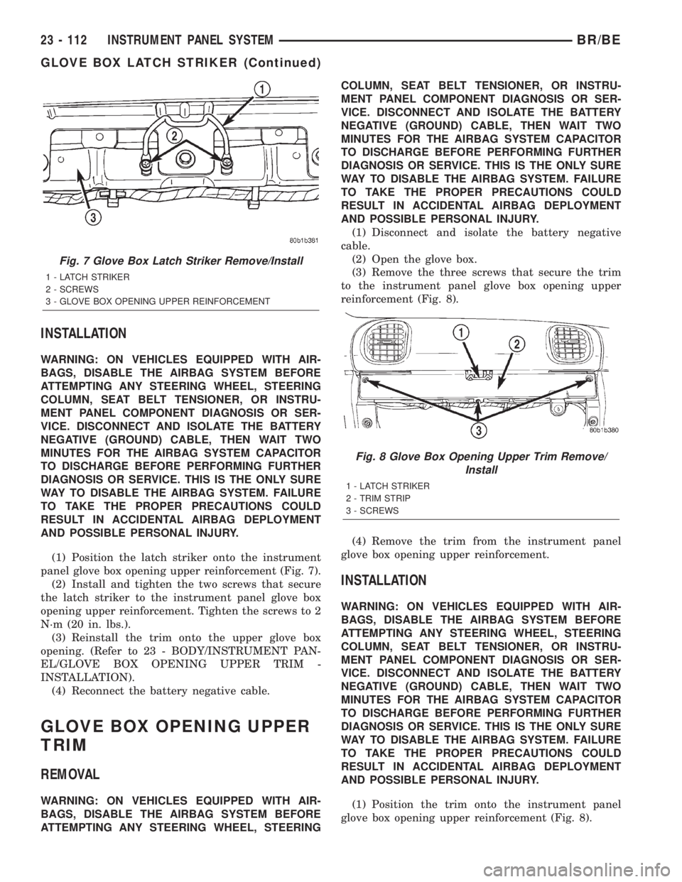
(1) Position the latch striker onto the instrument
panel glove box opening upper reinforcement (Fig. 7).
(2) Install and tighten the two screws that secure
the latch striker to the instrument panel glove box
opening upper reinforcement. Tighten the screws to 2
N´m (20 in. lbs.).
(3) Reinstall the trim onto the upper glove box
opening. (Refer to 23 - BODY/INSTRUMENT PAN-
EL/GLOVE BOX OPENING UPPER TRIM -
INSTALLATION).
(4) Reconnect the battery negative cable.
GLOVE BOX OPENING UPPER
TRIM
REMOVAL
WARNING: ON VEHICLES EQUIPPED WITH AIR-
BAGS, DISABLE THE AIRBAG SYSTEM BEFORE
ATTEMPTING ANY STEERING WHEEL, STEERINGCOLUMN, SEAT BELT TENSIONER, OR INSTRU-
MENT PANEL COMPONENT DIAGNOSIS OR SER-
VICE. DISCONNECT AND ISOLATE THE BATTERY
NEGATIVE (GROUND) CABLE, THEN WAIT TWO
MINUTES FOR THE AIRBAG SYSTEM CAPACITOR
TO DISCHARGE BEFORE PERFORMING FURTHER
DIAGNOSIS OR SERVICE. THIS IS THE ONLY SURE
WAY TO DISABLE THE AIRBAG SYSTEM. FAILURE
TO TAKE THE PROPER PRECAUTIONS COULD
RESULT IN ACCIDENTAL AIRBAG DEPLOYMENT
AND POSSIBLE PERSONAL INJURY.
(1) Disconnect and isolate the battery negative
cable.
(2) Open the glove box.
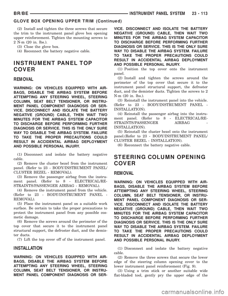
(3) Remove the three screws that secure the trim
to the instrument panel glove box opening upper
reinforcement (Fig. 8).
(4) Remove the trim from the instrument panel
glove box opening upper reinforcement.
INSTALLATION
WARNING: ON VEHICLES EQUIPPED WITH AIR-
BAGS, DISABLE THE AIRBAG SYSTEM BEFORE
ATTEMPTING ANY STEERING WHEEL, STEERING
COLUMN, SEAT BELT TENSIONER, OR INSTRU-
MENT PANEL COMPONENT DIAGNOSIS OR SER-
VICE. DISCONNECT AND ISOLATE THE BATTERY
NEGATIVE (GROUND) CABLE, THEN WAIT TWO
MINUTES FOR THE AIRBAG SYSTEM CAPACITOR
TO DISCHARGE BEFORE PERFORMING FURTHER
DIAGNOSIS OR SERVICE. THIS IS THE ONLY SURE
WAY TO DISABLE THE AIRBAG SYSTEM. FAILURE
TO TAKE THE PROPER PRECAUTIONS COULD
RESULT IN ACCIDENTAL AIRBAG DEPLOYMENT
AND POSSIBLE PERSONAL INJURY.
(1) Position the trim onto the instrument panel
glove box opening upper reinforcement (Fig. 8).
Fig. 7 Glove Box Latch Striker Remove/Install
1 - LATCH STRIKER
2 - SCREWS
3 - GLOVE BOX OPENING UPPER REINFORCEMENT
Fig. 8 Glove Box Opening Upper Trim Remove/
Install
1 - LATCH STRIKER
2 - TRIM STRIP
3 - SCREWS
23 - 112 INSTRUMENT PANEL SYSTEMBR/BE
GLOVE BOX LATCH STRIKER (Continued)
Page 2080 of 2255
(2) Install and tighten the three screws that secure
the trim to the instrument panel glove box opening
upper reinforcement. Tighten the mounting screws to
2 N´m (20 in. lbs.).
(3) Close the glove box.
(4) Reconnect the battery negative cable.
INSTRUMENT PANEL TOP
COVER
REMOVAL
WARNING: ON VEHICLES EQUIPPED WITH AIR-
BAGS, DISABLE THE AIRBAG SYSTEM BEFORE
ATTEMPTING ANY STEERING WHEEL, STEERING
COLUMN, SEAT BELT TENSIONER, OR INSTRU-
MENT PANEL COMPONENT DIAGNOSIS OR SER-
VICE. DISCONNECT AND ISOLATE THE BATTERY
NEGATIVE (GROUND) CABLE, THEN WAIT TWO
MINUTES FOR THE AIRBAG SYSTEM CAPACITOR
TO DISCHARGE BEFORE PERFORMING FURTHER
DIAGNOSIS OR SERVICE. THIS IS THE ONLY SURE
WAY TO DISABLE THE AIRBAG SYSTEM. FAILURE
TO TAKE THE PROPER PRECAUTIONS COULD
RESULT IN ACCIDENTAL AIRBAG DEPLOYMENT
AND POSSIBLE PERSONAL INJURY.
(1) Disconnect and isolate the battery negative
cable.
(2) Remove the cluster bezel from the instrument
panel. (Refer to 23 - BODY/INSTRUMENT PANEL/
CLUSTER BEZEL - REMOVAL).
(3) Remove the passenger airbag from the instru-
ment panel. (Refer to 8 - ELECTRICAL/RE-
STRAINTS/PASSENGER AIRBAG - REMOVAL).
(4) Remove the instrument panel from the vehicle.
(Refer to 23 - BODY/INSTRUMENT PANEL -
REMOVAL).
(5) Place the instrument panel on a suitable work
surface. Be certain to take the proper precautions to
protect the instrument panel from any possible cos-
metic damage.
(6) Remove the screws around the perimeter of the
top cover that secure it to the instrument panel
structural support, the defroster duct, and the demis-
ter ducts.
(7) Lift the top cover off of the instrument panel.
INSTALLATION
WARNING: ON VEHICLES EQUIPPED WITH AIR-
BAGS, DISABLE THE AIRBAG SYSTEM BEFORE
ATTEMPTING ANY STEERING WHEEL, STEERING
COLUMN, SEAT BELT TENSIONER, OR INSTRU-
MENT PANEL COMPONENT DIAGNOSIS OR SER-VICE. DISCONNECT AND ISOLATE THE BATTERY
NEGATIVE (GROUND) CABLE, THEN WAIT TWO
MINUTES FOR THE AIRBAG SYSTEM CAPACITOR
TO DISCHARGE BEFORE PERFORMING FURTHER
DIAGNOSIS OR SERVICE. THIS IS THE ONLY SURE
WAY TO DISABLE THE AIRBAG SYSTEM. FAILURE
TO TAKE THE PROPER PRECAUTIONS COULD
RESULT IN ACCIDENTAL AIRBAG DEPLOYMENT
AND POSSIBLE PERSONAL INJURY.
(1) Position the top cover onto the instrument
panel.
(2) Install and tighten the screws around the
perimeter of the top cover that secure it to the
instrument panel structural support, the defroster
duct, and the demister ducts. Tighten the screws to 2
N´m (20 in. lbs.).
(3) Reinstall the instrument panel into the vehicle.
(Refer to 23 - BODY/INSTRUMENT PANEL -
INSTALLATION).
(4) Reinstall the passenger airbag into the instru-
ment panel. (Refer to 8 - ELECTRICAL/RE-
STRAINTS/PASSENGER AIRBAG -
INSTALLATION).
(5) Reinstall the cluster bezel onto the instrument
panel.(Refer to 23 - BODY/INSTRUMENT PANEL/
CLUSTER BEZEL - INSTALLATION).
(6) Reconnect the battery negative cable.
STEERING COLUMN OPENING
COVER
REMOVAL
WARNING: ON VEHICLES EQUIPPED WITH AIR-
BAGS, DISABLE THE AIRBAG SYSTEM BEFORE
ATTEMPTING ANY STEERING WHEEL, STEERING
COLUMN, SEAT BELT TENSIONER, OR INSTRU-
MENT PANEL COMPONENT DIAGNOSIS OR SER-
VICE. DISCONNECT AND ISOLATE THE BATTERY
NEGATIVE (GROUND) CABLE, THEN WAIT TWO
MINUTES FOR THE AIRBAG SYSTEM CAPACITOR
TO DISCHARGE BEFORE PERFORMING FURTHER
DIAGNOSIS OR SERVICE. THIS IS THE ONLY SURE
WAY TO DISABLE THE AIRBAG SYSTEM. FAILURE
TO TAKE THE PROPER PRECAUTIONS COULD
RESULT IN ACCIDENTAL AIRBAG DEPLOYMENT
AND POSSIBLE PERSONAL INJURY.
(1) Disconnect and isolate the battery negative
cable.
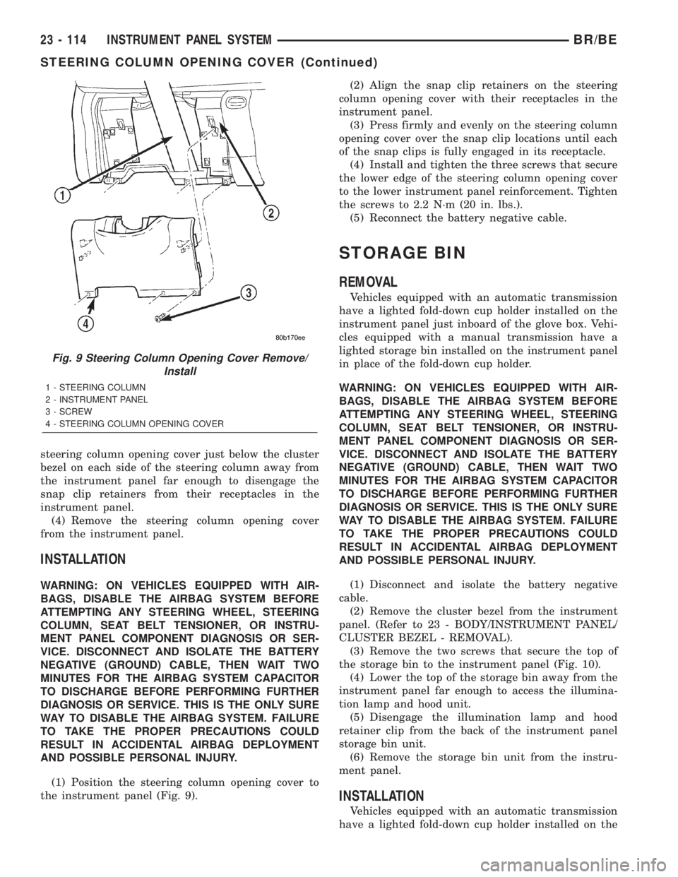
(2) Remove the three screws that secure the lower
edge of the steering column opening cover to the
lower instrument panel reinforcement (Fig. 9).
(3) Using a trim stick or another suitable wide
flat-bladed tool, gently pry the upper edge of the
BR/BEINSTRUMENT PANEL SYSTEM 23 - 113
GLOVE BOX OPENING UPPER TRIM (Continued)
Page 2081 of 2255
steering column opening cover just below the cluster
bezel on each side of the steering column away from
the instrument panel far enough to disengage the
snap clip retainers from their receptacles in the
instrument panel.
(4) Remove the steering column opening cover
from the instrument panel.
INSTALLATION
WARNING: ON VEHICLES EQUIPPED WITH AIR-
BAGS, DISABLE THE AIRBAG SYSTEM BEFORE
ATTEMPTING ANY STEERING WHEEL, STEERING
COLUMN, SEAT BELT TENSIONER, OR INSTRU-
MENT PANEL COMPONENT DIAGNOSIS OR SER-
VICE. DISCONNECT AND ISOLATE THE BATTERY
NEGATIVE (GROUND) CABLE, THEN WAIT TWO
MINUTES FOR THE AIRBAG SYSTEM CAPACITOR
TO DISCHARGE BEFORE PERFORMING FURTHER
DIAGNOSIS OR SERVICE. THIS IS THE ONLY SURE
WAY TO DISABLE THE AIRBAG SYSTEM. FAILURE
TO TAKE THE PROPER PRECAUTIONS COULD
RESULT IN ACCIDENTAL AIRBAG DEPLOYMENT
AND POSSIBLE PERSONAL INJURY.
(1) Position the steering column opening cover to
the instrument panel (Fig. 9).(2) Align the snap clip retainers on the steering
column opening cover with their receptacles in the
instrument panel.
(3) Press firmly and evenly on the steering column
opening cover over the snap clip locations until each
of the snap clips is fully engaged in its receptacle.
(4) Install and tighten the three screws that secure
the lower edge of the steering column opening cover
to the lower instrument panel reinforcement. Tighten
the screws to 2.2 N´m (20 in. lbs.).
(5) Reconnect the battery negative cable.
STORAGE BIN
REMOVAL
Vehicles equipped with an automatic transmission
have a lighted fold-down cup holder installed on the
instrument panel just inboard of the glove box. Vehi-
cles equipped with a manual transmission have a
lighted storage bin installed on the instrument panel
in place of the fold-down cup holder.
WARNING: ON VEHICLES EQUIPPED WITH AIR-
BAGS, DISABLE THE AIRBAG SYSTEM BEFORE
ATTEMPTING ANY STEERING WHEEL, STEERING
COLUMN, SEAT BELT TENSIONER, OR INSTRU-
MENT PANEL COMPONENT DIAGNOSIS OR SER-
VICE. DISCONNECT AND ISOLATE THE BATTERY
NEGATIVE (GROUND) CABLE, THEN WAIT TWO
MINUTES FOR THE AIRBAG SYSTEM CAPACITOR
TO DISCHARGE BEFORE PERFORMING FURTHER
DIAGNOSIS OR SERVICE. THIS IS THE ONLY SURE
WAY TO DISABLE THE AIRBAG SYSTEM. FAILURE
TO TAKE THE PROPER PRECAUTIONS COULD
RESULT IN ACCIDENTAL AIRBAG DEPLOYMENT
AND POSSIBLE PERSONAL INJURY.
(1) Disconnect and isolate the battery negative
cable.
(2) Remove the cluster bezel from the instrument
panel. (Refer to 23 - BODY/INSTRUMENT PANEL/
CLUSTER BEZEL - REMOVAL).
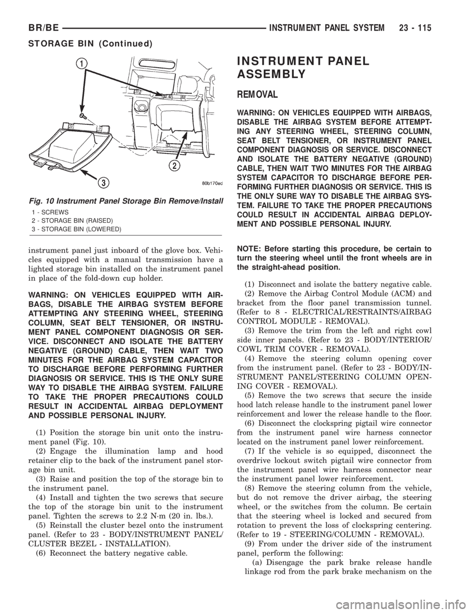
(3) Remove the two screws that secure the top of
the storage bin to the instrument panel (Fig. 10).
(4) Lower the top of the storage bin away from the
instrument panel far enough to access the illumina-
tion lamp and hood unit.
(5) Disengage the illumination lamp and hood
retainer clip from the back of the instrument panel
storage bin unit.
(6) Remove the storage bin unit from the instru-
ment panel.
INSTALLATION
Vehicles equipped with an automatic transmission
have a lighted fold-down cup holder installed on the
Fig. 9 Steering Column Opening Cover Remove/
Install
1 - STEERING COLUMN
2 - INSTRUMENT PANEL
3 - SCREW
4 - STEERING COLUMN OPENING COVER
23 - 114 INSTRUMENT PANEL SYSTEMBR/BE
STEERING COLUMN OPENING COVER (Continued)
Page 2082 of 2255
instrument panel just inboard of the glove box. Vehi-
cles equipped with a manual transmission have a
lighted storage bin installed on the instrument panel
in place of the fold-down cup holder.
WARNING: ON VEHICLES EQUIPPED WITH AIR-
BAGS, DISABLE THE AIRBAG SYSTEM BEFORE
ATTEMPTING ANY STEERING WHEEL, STEERING
COLUMN, SEAT BELT TENSIONER, OR INSTRU-
MENT PANEL COMPONENT DIAGNOSIS OR SER-
VICE. DISCONNECT AND ISOLATE THE BATTERY
NEGATIVE (GROUND) CABLE, THEN WAIT TWO
MINUTES FOR THE AIRBAG SYSTEM CAPACITOR
TO DISCHARGE BEFORE PERFORMING FURTHER
DIAGNOSIS OR SERVICE. THIS IS THE ONLY SURE
WAY TO DISABLE THE AIRBAG SYSTEM. FAILURE
TO TAKE THE PROPER PRECAUTIONS COULD
RESULT IN ACCIDENTAL AIRBAG DEPLOYMENT
AND POSSIBLE PERSONAL INJURY.
(1) Position the storage bin unit onto the instru-
ment panel (Fig. 10).
(2) Engage the illumination lamp and hood
retainer clip to the back of the instrument panel stor-
age bin unit.
(3) Raise and position the top of the storage bin to
the instrument panel.
(4) Install and tighten the two screws that secure
the top of the storage bin unit to the instrument
panel. Tighten the screws to 2.2 N´m (20 in. lbs.).
(5) Reinstall the cluster bezel onto the instrument
panel. (Refer to 23 - BODY/INSTRUMENT PANEL/
CLUSTER BEZEL - INSTALLATION).
(6) Reconnect the battery negative cable.
INSTRUMENT PANEL
ASSEMBLY
REMOVAL
WARNING: ON VEHICLES EQUIPPED WITH AIRBAGS,
DISABLE THE AIRBAG SYSTEM BEFORE ATTEMPT-
ING ANY STEERING WHEEL, STEERING COLUMN,
SEAT BELT TENSIONER, OR INSTRUMENT PANEL
COMPONENT DIAGNOSIS OR SERVICE. DISCONNECT
AND ISOLATE THE BATTERY NEGATIVE (GROUND)
CABLE, THEN WAIT TWO MINUTES FOR THE AIRBAG
SYSTEM CAPACITOR TO DISCHARGE BEFORE PER-
FORMING FURTHER DIAGNOSIS OR SERVICE. THIS IS
THE ONLY SURE WAY TO DISABLE THE AIRBAG SYS-
TEM. FAILURE TO TAKE THE PROPER PRECAUTIONS
COULD RESULT IN ACCIDENTAL AIRBAG DEPLOY-
MENT AND POSSIBLE PERSONAL INJURY.
NOTE: Before starting this procedure, be certain to
turn the steering wheel until the front wheels are in
the straight-ahead position.
(1)
Disconnect and isolate the battery negative cable.
(2) Remove the Airbag Control Module (ACM) and
bracket from the floor panel transmission tunnel.
(Refer to 8 - ELECTRICAL/RESTRAINTS/AIRBAG
CONTROL MODULE - REMOVAL).
(3) Remove the trim from the left and right cowl
side inner panels. (Refer to 23 - BODY/INTERIOR/
COWL TRIM COVER - REMOVAL).
(4) Remove the steering column opening cover
from the instrument panel. (Refer to 23 - BODY/IN-
STRUMENT PANEL/STEERING COLUMN OPEN-
ING COVER - REMOVAL).
(5)
Remove the two screws that secure the inside
hood latch release handle to the instrument panel lower
reinforcement and lower the release handle to the floor.
(6)Disconnect the clockspring pigtail wire connector
from the instrument panel wire harness connector
located on the instrument panel lower reinforcement.
(7) If the vehicle is so equipped, disconnect the
overdrive lockout switch pigtail wire connector from
the instrument panel wire harness connector near
the instrument panel lower reinforcement.
(8) Remove the steering column from the vehicle,
but do not remove the driver airbag, the steering
wheel, or the switches from the column. Be certain
that the steering wheel is locked and secured from
rotation to prevent the loss of clockspring centering.
(Refer to 19 - STEERING/COLUMN - REMOVAL).
(9) From under the driver side of the instrument
panel, perform the following:
(a) Disengage the park brake release handle
linkage rod from the park brake mechanism on the
Fig. 10 Instrument Panel Storage Bin Remove/Install
1 - SCREWS
2 - STORAGE BIN (RAISED)
3 - STORAGE BIN (LOWERED)
BR/BEINSTRUMENT PANEL SYSTEM 23 - 115
STORAGE BIN (Continued)
Page 2084 of 2255
wire harness connectors from the heater-A/C housing
wire harness connectors.
(15) With the aid of an assistant, remove the tem-
porary hook and lift the instrument panel assembly
off of the roll-down bracket screws and remove it
from the vehicle.
INSTALLATION
WARNING: ON VEHICLES EQUIPPED WITH AIRBAGS,
DISABLE THE AIRBAG SYSTEM BEFORE ATTEMPT-
ING ANY STEERING WHEEL, STEERING COLUMN,
SEAT BELT TENSIONER, OR INSTRUMENT PANEL
COMPONENT DIAGNOSIS OR SERVICE. DISCONNECT
AND ISOLATE THE BATTERY NEGATIVE (GROUND)
CABLE, THEN WAIT TWO MINUTES FOR THE AIRBAG
SYSTEM CAPACITOR TO DISCHARGE BEFORE PER-
FORMING FURTHER DIAGNOSIS OR SERVICE. THIS IS
THE ONLY SURE WAY TO DISABLE THE AIRBAG SYS-
TEM. FAILURE TO TAKE THE PROPER PRECAUTIONS
COULD RESULT IN ACCIDENTAL AIRBAG DEPLOY-
MENT AND POSSIBLE PERSONAL INJURY.
(1)With the aid of an assistant, load the instrument
panel assembly onto the roll-down bracket screws on
the cowl side inner panels in the vehicle (Fig. 11).
Install a temporary hook in the center hole on top of the
instrument panel. Secure the other end of the hook to
the center hole in the top of the dash panel. The hook
should support the instrument panel in its rolled down
position about 46 cm (18 inches) from the dash panel.
(2) With the instrument panel supported in the
roll-down position, reconnect the instrument panel
wire harness connectors to the heater-A/C housing
wire harness connectors.
(3) Remove the temporary hook from the instru-
ment panel and roll the instrument panel up to its
installed position against the dash panel.
(4) Install and tighten the five screws that secure
the top of the instrument panel to the top of the dash
panel. Tighten the screws to 3.2 N´m (28 in. lbs.).
(5) Tighten the right and left instrument panel
cowl side roll-down bracket screws. Tighten the
screws to 11.9 N´m (105 in. lbs.).
(6) From under the passenger side of the instru-
ment panel, reconnect the two halves of the radio
antenna coaxial cable connector.
(7) From under the driver side of the instrument
panel, perform the following:
(a) Engage the park brake release handle link-
age rod with the park brake mechanism on the left
cowl side inner panel. (Refer to 5 - BRAKES/PARK-
ING BRAKE/RELEASE - INSTALLATION).
(b) Reconnect the instrument panel wire harness
connector to the park brake switch on the park
brake mechanism.(c) Reconnect the three connectors (one from the
body wire harness, and two from the headlamp and
dash wire harness) to the three connector recepta-
cles located closest to the dash panel on the back of
the Junction Block (JB).
(d)
Reconnect the headlamp and dash wire harness
to instrument panel wire harness bulkhead connector
and tighten the screw in the center of the connector.
Tighten the screw to 3.5 N´m (31 in. lbs.).
(e) Reconnect the instrument panel wire harness
to door wire harness connector located directly
below the instrument panel wire harness to head-
lamp and dash wire harness bulkhead connector.
(f) If the vehicle is equipped with the Infinity
sound system option, reconnect the Infinity wire
harness connector to the instrument panel wire
harness connector that is secured to the outboard
side of the instrument panel wire harness to head-
lamp and dash wire harness bulkhead connector.
(g) Reconnect the instrument panel wire harness
connector to the stop lamp switch.
(h) Reconnect the heater-A/C housing vacuum
harness connector to the heater-A/C control vac-
uum harness connector located near the left end of
the heater-A/C housing.
(8) Reinstall the steering column into the vehicle.
Be certain that the steering wheel was locked and
secured from rotation to prevent the loss of clock-
spring centering. (Refer to 19 - STEERING/COL-
UMN - INSTALLATION).
(9) If the vehicle is so equipped, reconnect the
overdrive lockout switch pigtail wire connector to the
instrument panel wire harness connector near the
instrument panel lower reinforcement.
(10) Reconnect the clockspring pigtail wire connec-
tor to the instrument panel wire harness connector
at the instrument panel lower reinforcement.
(11) Position the inside hood latch release handle
to the instrument panel lower reinforcement.
(12) Install and tighten the two screws that secure
the inside hood latch release handle to the instru-
ment panel lower reinforcement. Tighten the screws
to 2.8 N´m (25 in. lbs.).
(13) Reinstall the steering column opening cover
onto the instrument panel. (Refer to 23 - BODY/IN-
STRUMENT PANEL/STEERING COLUMN OPEN-
ING COVER - INSTALLATION).
(14) Reinstall the trim onto the left and right cowl
side inner panels. (Refer to 23 - BODY/INTERIOR/
COWL TRIM COVER - INSTALLATION).
(15) Reinstall the Airbag Control Module (ACM)
and bracket onto the floor panel transmission tunnel.
(Refer to 8 - ELECTRICAL/RESTRAINTS/AIRBAG
CONTROL MODULE - INSTALLATION).
(16) Reconnect the battery negative cable.
BR/BEINSTRUMENT PANEL SYSTEM 23 - 117
INSTRUMENT PANEL ASSEMBLY (Continued)
Page 2132 of 2255
LOCATING VACUUM LEAKS
WARNING: ON VEHICLES EQUIPPED WITH AIR-
BAGS, DISABLE THE AIRBAG SYSTEM BEFORE
ATTEMPTING ANY STEERING WHEEL, STEERING
COLUMN, OR INSTRUMENT PANEL COMPONENT
DIAGNOSIS OR SERVICE. DISCONNECT AND ISO-
LATE THE BATTERY NEGATIVE (GROUND) CABLE,
THEN WAIT TWO MINUTES FOR THE AIRBAG SYS-
TEM CAPACITOR TO DISCHARGE BEFORE PER-
FORMING FURTHER DIAGNOSIS OR SERVICE. THIS
IS THE ONLY SURE WAY TO DISABLE THE AIRBAG
SYSTEM. FAILURE TO TAKE THE PROPER PRE-
CAUTIONS COULD RESULT IN AN ACCIDENTAL
AIRBAG DEPLOYMENT AND POSSIBLE PERSONAL
INJURY.
(1) Disconnect the vacuum harness connector
located between the a/c heater control and the HVAC
housing under the instrument panel.
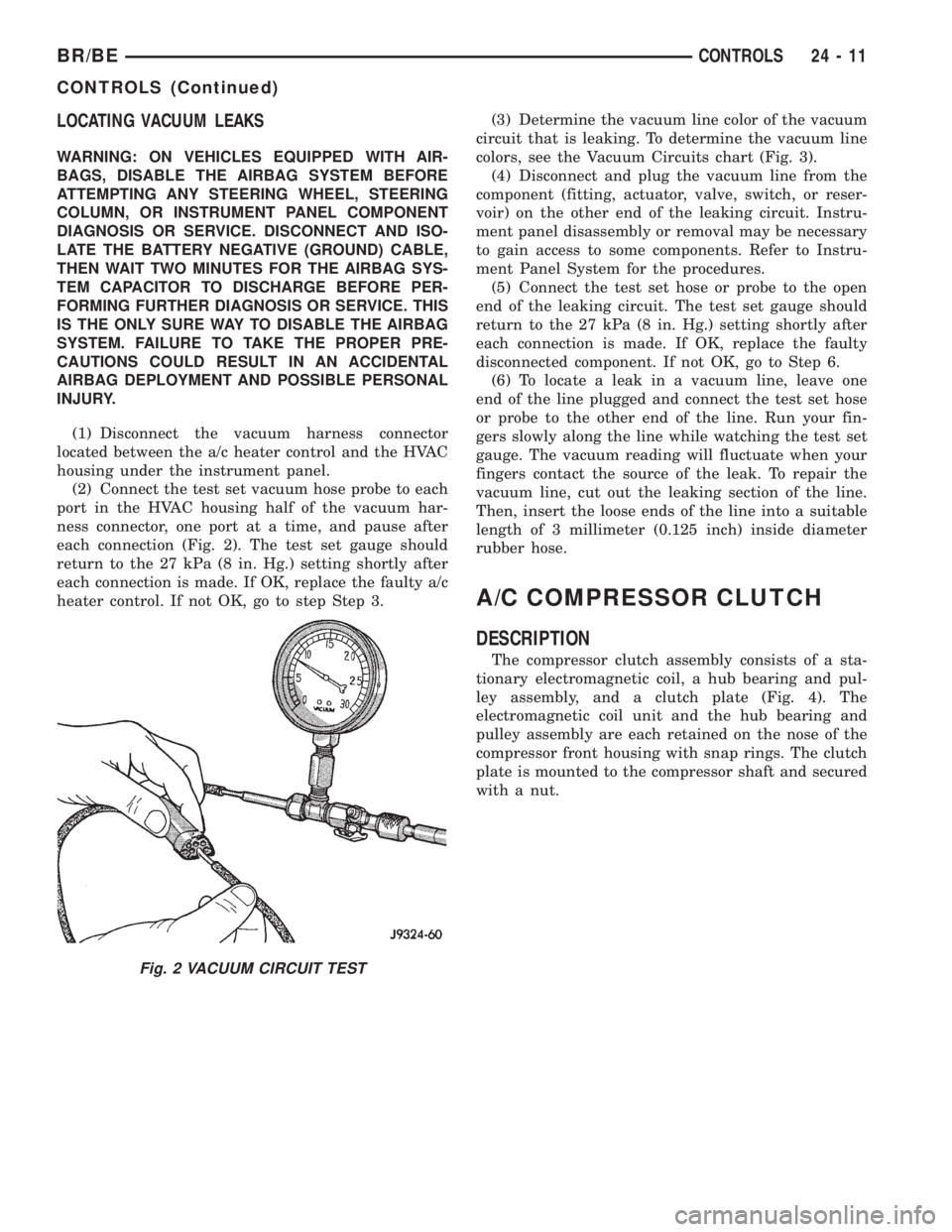
(2) Connect the test set vacuum hose probe to each
port in the HVAC housing half of the vacuum har-
ness connector, one port at a time, and pause after
each connection (Fig. 2). The test set gauge should
return to the 27 kPa (8 in. Hg.) setting shortly after
each connection is made. If OK, replace the faulty a/c
heater control. If not OK, go to step Step 3.(3) Determine the vacuum line color of the vacuum
circuit that is leaking. To determine the vacuum line
colors, see the Vacuum Circuits chart (Fig. 3).
(4) Disconnect and plug the vacuum line from the
component (fitting, actuator, valve, switch, or reser-
voir) on the other end of the leaking circuit. Instru-
ment panel disassembly or removal may be necessary
to gain access to some components. Refer to Instru-
ment Panel System for the procedures.
(5) Connect the test set hose or probe to the open
end of the leaking circuit. The test set gauge should
return to the 27 kPa (8 in. Hg.) setting shortly after
each connection is made. If OK, replace the faulty
disconnected component. If not OK, go to Step 6.
(6) To locate a leak in a vacuum line, leave one
end of the line plugged and connect the test set hose
or probe to the other end of the line. Run your fin-
gers slowly along the line while watching the test set
gauge. The vacuum reading will fluctuate when your
fingers contact the source of the leak. To repair the
vacuum line, cut out the leaking section of the line.
Then, insert the loose ends of the line into a suitable
length of 3 millimeter (0.125 inch) inside diameter
rubber hose.
A/C COMPRESSOR CLUTCH
DESCRIPTION
The compressor clutch assembly consists of a sta-
tionary electromagnetic coil, a hub bearing and pul-
ley assembly, and a clutch plate (Fig. 4). The
electromagnetic coil unit and the hub bearing and
pulley assembly are each retained on the nose of the
compressor front housing with snap rings. The clutch
plate is mounted to the compressor shaft and secured
with a nut.
Fig. 2 VACUUM CIRCUIT TEST
BR/BECONTROLS 24 - 11
CONTROLS (Continued)
Page 2134 of 2255
OPERATION
The compressor clutch assembly provides the
means to engage and disengage the compressor from
the engine serpentine accessory drive belt. When the
clutch coil is energized, it magnetically draws the
clutch into contact with the pulley and drives the
compressor shaft. When the coil is not energized, the
pulley freewheels on the clutch hub bearing, which is
part of the pulley. The compressor clutch and coil are
the only serviced parts on the compressor.
The compressor clutch engagement is controlled by
several components: the a/c heater mode control
switch, the a/c loss of charge switch, the a/c pressure
transducer, the compressor clutch relay, the evapora-
tor temperature sensor and the Powertrain Control
Module (PCM). The PCM may delay compressor
clutch engagement for up to thirty seconds(Refer to 8
- ELECTRICAL/ELECTRONIC CONTROL MOD-
ULES/POWERTRAIN CONTROL MODULE -
DESCRIPTION).
DIAGNOSIS AND TESTING - A/C COMPRESSOR
CLUTCH COIL
For circuit descriptions and diagrams, (Refer to
Appropriate Wiring Information). The battery must
be fully-charged before performing the following
tests. Refer to Battery for more information.
(1) Connect an ammeter (0 to 10 ampere scale) in
series with the clutch coil terminal. Use a voltmeter
(0 to 20 volt scale) with clip-type leads for measuring
the voltage across the battery and the compressor
clutch coil.(2) With the a/c heater mode control switch in any
A/C mode, and the blower motor switch in the lowest
speed position, start the engine and run it at normal
idle.
(3) The compressor clutch coil voltage should read
within 0.2 volts of the battery voltage. If there is
voltage at the clutch coil, but the reading is not
within 0.2 volts of the battery voltage, test the clutch
coil feed circuit for excessive voltage drop and repair
as required. If there is no voltage reading at the
clutch coil, use a DRB IIItscan tool and (Refer to
Appropriate Diagnostic Information) for testing of the
compressor clutch circuit. The following components
must be checked and repaired as required before you
can complete testing of the clutch coil:
²Fuses in the junction block and the Power Dis-
tribution Center (PDC)
²A/C Heater mode control switch
²Compressor clutch relay
²A/C High Pressure Switch
²A/C Low Pressure Switch
²Powertrain Control Module (PCM).
(4) The compressor clutch coil is acceptable if the
current draw measured at the clutch coil is 2.0 to 3.9
amperes with the electrical system voltage at 11.5 to
12.5 volts. This should only be checked with the work
area temperature at 21É C (70É F). If system voltage
is more than 12.5 volts, add electrical loads by turn-
ing on electrical accessories until the system voltage
drops below 12.5 volts.
(a) If the clutch coil current reading is four
amperes or more, the coil is shorted and should be
replaced.
(b) If the clutch coil current reading is zero, the
coil is open and should be replaced.
STANDARD PROCEDURE - A/C COMPRESSOR
CLUTCH BREAK-IN
After a new compressor clutch has been installed,
cycle the compressor clutch approximately twenty
times (five seconds on, then five seconds off). During
this procedure, set the A/C Heater control to the
Recirculation Mode, the blower motor switch in the
highest speed position, and the engine speed at 1500
to 2000 rpm. This procedure (burnishing) will seat
the opposing friction surfaces and provide a higher
compressor clutch torque capability.
REMOVAL
The refrigerant system can remain fully-charged
during compressor clutch, pulley, or coil replacement.
The compressor clutch can be serviced in the vehicle.
(1) Disconnect and isolate the battery negative
cable.
(2) On models with the diesel engine option,
remove the compressor from the engine. Do not
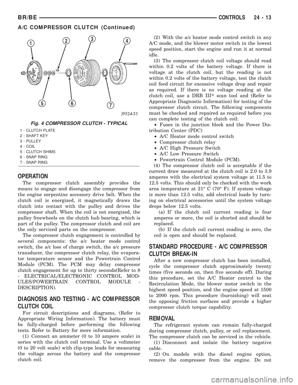
Fig. 4 COMPRESSOR CLUTCH - TYPICAL
1 - CLUTCH PLATE
2 - SHAFT KEY
3 - PULLEY
4 - COIL
5 - CLUTCH SHIMS
6 - SNAP RING
7 - SNAP RING
BR/BECONTROLS 24 - 13
A/C COMPRESSOR CLUTCH (Continued)
Page 2140 of 2255
(3) On vehicles with air conditioning, turn the
temperature control knob to the extreme counter
clockwise (Cool) position, and set the mode control
switch knob to the Bi-Level (A/C) position. The out-
side (recirculation) air door should be open to outside
air. If not OK, (Refer to 24 - HEATING & AIR CON-
DITIONING/CONTROLS - DIAGNOSIS AND TEST-
ING - VACUUM SYSTEM).
(4) Open the vehicle windows. Test the blower
motor operation in all speeds. If not OK, (Refer to 24
- HEATING & AIR CONDITIONING/DISTRIBU-
TION/BLOWER MOTOR - DIAGNOSIS AND TEST-
ING).
(5) On vehicles with air conditioning, the compres-
sor should be running and the air conditioning sys-
tem in operation unless the ambient air temperature
is below about -1É C (30É F). If not OK, (Refer to 24 -
HEATING & AIR CONDITIONING - DIAGNOSIS
AND TESTING - A/C PERFORMANCE).
(6) Check the mode control switch operation. The
heater and air conditioner systems should respond as
described in the owner's manual in the vehicle glove
box to each mode selected. Reduce the engine speed
to normal idle. The vacuum will be high at low idle
and the vacuum actuators should respond quickly. If
not OK, (Refer to 24 - HEATING & AIR CONDI-
TIONING/CONTROLS - DIAGNOSIS AND TEST-
ING - VACUUM SYSTEM).
(7) If the vacuum tests, and the electrical compo-
nent and circuit tests reveal no problems, disassem-
ble the HVAC housing to inspect for mechanical
misalignment or binding of the mode doors (Refer to
24 - HEATING & AIR CONDITIONING/DISTRIBU-
TION/HVAC HOUSING - DISASSEMBLY)
REMOVAL
WARNING: ON VEHICLES EQUIPPED WITH AIR-
BAGS, DISABLE THE AIRBAG SYSTEM BEFORE
ATTEMPTING ANY STEERING WHEEL, STEERING
COLUMN, OR INSTRUMENT PANEL COMPONENT
DIAGNOSIS OR SERVICE. DISCONNECT AND ISO-
LATE THE BATTERY NEGATIVE (GROUND) CABLE,
THEN WAIT TWO MINUTES FOR THE AIRBAG SYS-
TEM CAPACITOR TO DISCHARGE BEFORE PER-
FORMING FURTHER DIAGNOSIS OR SERVICE. THIS
IS THE ONLY SURE WAY TO DISABLE THE AIRBAG
SYSTEM. FAILURE TO TAKE THE PROPER PRE-
CAUTIONS COULD RESULT IN AN ACCIDENTAL
AIRBAG DEPLOYMENT AND POSSIBLE PERSONAL
INJURY.
(1) Disconnect and isolate the battery negative
cable.
(2) Reach under the instrument panel near the
driver side of the floor panel transmission tunnel andunplug the a/c heater control to HVAC housing vac-
uum harness connector.
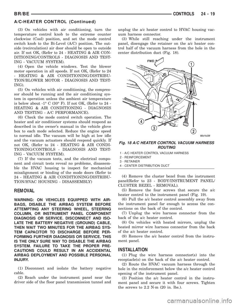
(3) While still reaching under the instrument
panel, disengage the retainer on the a/c heater con-
trol half of the vacuum harness from the hole in the
center distribution duct (Fig. 18).
(4) Remove the cluster bezel from the instrument
panel(Refer to 23 - BODY/INSTRUMENT PANEL/
CLUSTER BEZEL - REMOVAL).
(5) Remove the four screws that secure the a/c
heater control to the instrument panel (Fig. 19).
(6) Pull the a/c heater control assembly away from
the instrument panel far enough to access the con-
nections on the back of the control.
(7) Unplug the wire harness connector from the
back of the a/c heater control.
(8) On vehicles with heated mirrors, unplug the
heated mirror wire harness connector from the back
of the a/c heater control.
(9) Remove the a/c heater control from the instru-
ment panel.
INSTALLATION
(1) Plug the wire harness connector(s) into the
receptacle(s) on the back of the a/c heater control.
(2) Route the HVAC vacuum harness through the
hole in the reinforcement below the a/c heater control
opening of the instrument panel.
(3) Position the a/c heater control in the instru-
ment panel and secure it with four screws. Tighten
the screws to 2.2 N´m (20 in. lbs.).
Fig. 18 A/C HEATER CONTROL VACUUM HARNESS
ROUTING
1 - A/C HEATER CONTROL VACUUM HARNESS
2 - REINFORCEMENT
3 - RETAINER
4 - CENTER DISTRIBUTION DUCT
BR/BECONTROLS 24 - 19
A/C-HEATER CONTROL (Continued)