2002 DODGE RAM wheel
[x] Cancel search: wheelPage 1965 of 2255
SPARE TIRE
DESCRIPTION
The temporary spare tire is designed for emer-
gency use only. The original tire should be repaired
or replaced at the first opportunity, then reinstalled.
Do not exceed speeds of 50 M.P.H. when using the
temporary spare tire. Refer to Owner's Manual for
complete details.
WHEELS
DESCRIPTION
Original equipment wheels are designed for the
specified Maximum Vehicle Capacity.
All models use steel or cast aluminum drop center
wheels.
Cast aluminum wheels require special balance
weights and alignment equipment.
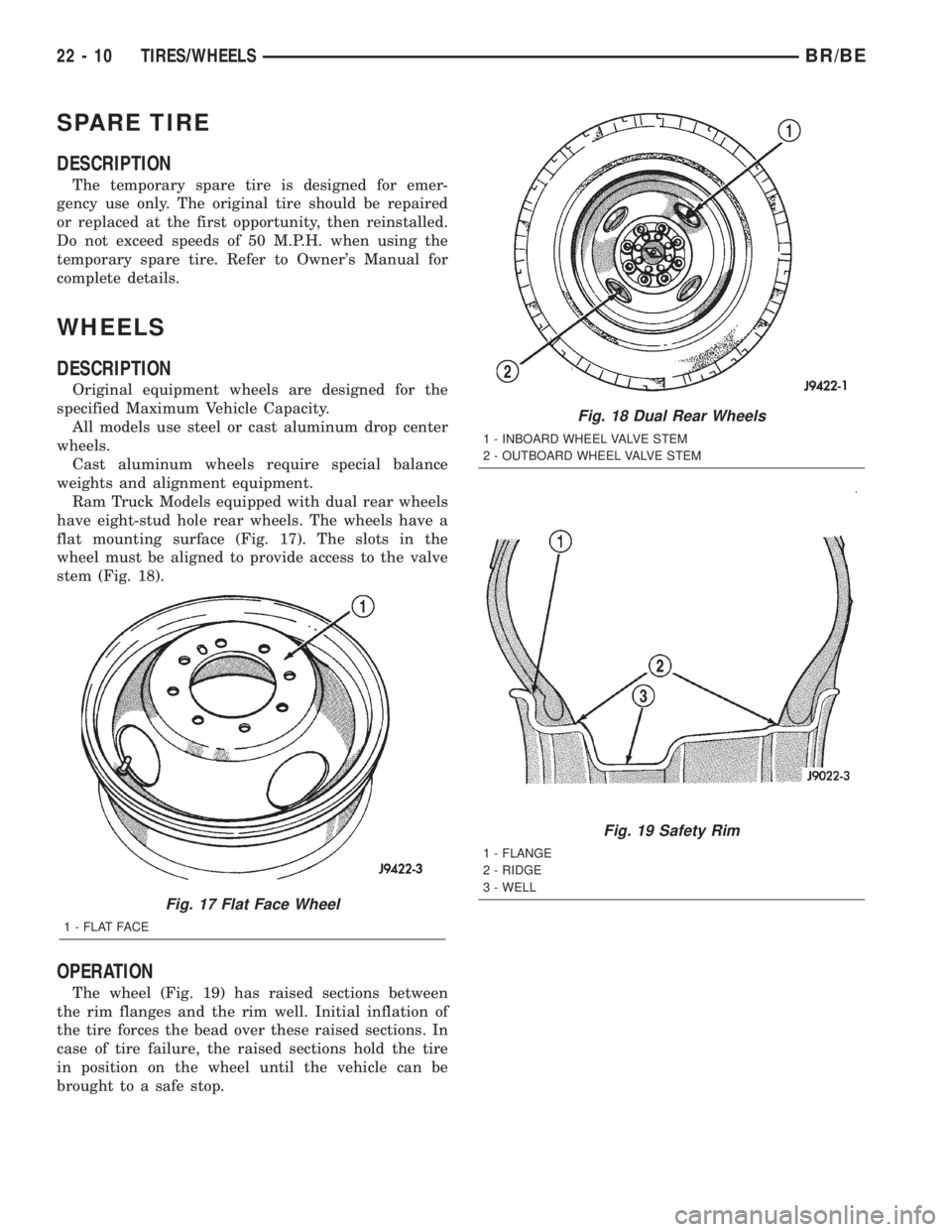
Ram Truck Models equipped with dual rear wheels
have eight-stud hole rear wheels. The wheels have a
flat mounting surface (Fig. 17). The slots in the
wheel must be aligned to provide access to the valve
stem (Fig. 18).
OPERATION
The wheel (Fig. 19) has raised sections between
the rim flanges and the rim well. Initial inflation of
the tire forces the bead over these raised sections. In
case of tire failure, the raised sections hold the tire
in position on the wheel until the vehicle can be
brought to a safe stop.
Fig. 17 Flat Face Wheel
1 - FLAT FACE
Fig. 18 Dual Rear Wheels
1 - INBOARD WHEEL VALVE STEM
2 - OUTBOARD WHEEL VALVE STEM
Fig. 19 Safety Rim
1 - FLANGE
2 - RIDGE
3 - WELL
22 - 10 TIRES/WHEELSBR/BE
Page 1966 of 2255
DIAGNOSIS AND TESTING
WHEEL INSPECTION
Inspect wheels for:
²Excessive run out
²Dents or cracks
²Damaged wheel lug nut holes
²Air Leaks from any area or surface of the rim
NOTE: Do not attempt to repair a wheel by hammer-
ing, heating or welding.
If a wheel is damaged an original equipment
replacement wheel should be used. When obtaining
replacement wheels, they should be equivalent in
load carrying capacity. The diameter, width, offset,
pilot hole and bolt circle of the wheel should be the
same as the original wheel.
WARNING: FAILURE TO USE EQUIVALENT REPLACE-
MENT WHEELS MAY ADVERSELY AFFECT THE
SAFETY AND HANDLING OF THE VEHICLE. USED
WHEELS ARE NOT RECOMMENDED. THE SERVICE
HISTORY OF THE WHEEL MAY HAVE INCLUDED
SEVERE TREATMENT OR VERY HIGH MILEAGE. THE
RIM COULD FAIL WITHOUT WARNING.
STANDARD PROCEDURE - DUAL REAR WHEEL
INSTALLATION
Dual rear wheels use a special heavy duty lug nut
wrench. It is recommended to remove and install dual
rear wheels only when the proper wrench is available.
The wrench is also use to remove wheel center caps for
more information refer to Owner's Manual.
The tires on both wheels must be completely raised
off the ground when tightening the lug nuts. This
will ensure correct wheel centering and maximum
wheel clamping.
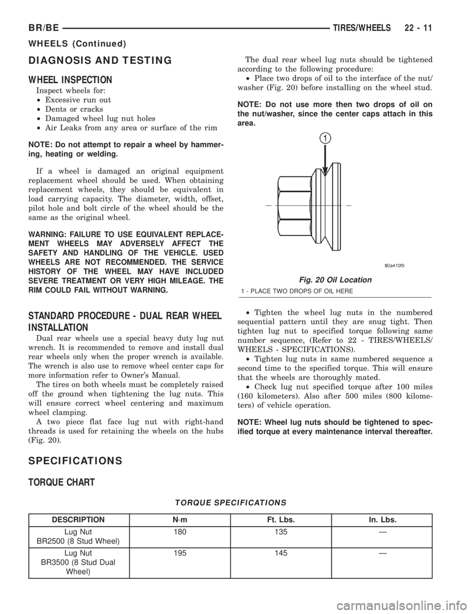
A two piece flat face lug nut with right-hand
threads is used for retaining the wheels on the hubs
(Fig. 20).The dual rear wheel lug nuts should be tightened
according to the following procedure:
²Place two drops of oil to the interface of the nut/
washer (Fig. 20) before installing on the wheel stud.
NOTE: Do not use more then two drops of oil on
the nut/washer, since the center caps attach in this
area.
²Tighten the wheel lug nuts in the numbered
sequential pattern until they are snug tight. Then
tighten lug nut to specified torque following same
number sequence, (Refer to 22 - TIRES/WHEELS/
WHEELS - SPECIFICATIONS).
²Tighten lug nuts in same numbered sequence a
second time to the specified torque. This will ensure
that the wheels are thoroughly mated.
²Check lug nut specified torque after 100 miles
(160 kilometers). Also after 500 miles (800 kilome-
ters) of vehicle operation.
NOTE: Wheel lug nuts should be tightened to spec-
ified torque at every maintenance interval thereafter.
SPECIFICATIONS
TORQUE CHART
TORQUE SPECIFICATIONS
DESCRIPTION N´m Ft. Lbs. In. Lbs.
Lug Nut
BR2500 (8 Stud Wheel)180 135 Ð
Lug Nut
BR3500 (8 Stud Dual
Wheel)195 145 Ð
Fig. 20 Oil Location
1 - PLACE TWO DROPS OF OIL HERE
BR/BETIRES/WHEELS 22 - 11
WHEELS (Continued)
Page 1967 of 2255
STUDS
REMOVAL
(1) Raise and support the vehicle.
(2) Remove the wheel and tire assembly.
(3) Remove the brake caliper, caliper adapter and
rotor, (Refer to 5 - BRAKES/HYDRAULIC/MECHAN-
ICAL/ROTORS - REMOVAL).
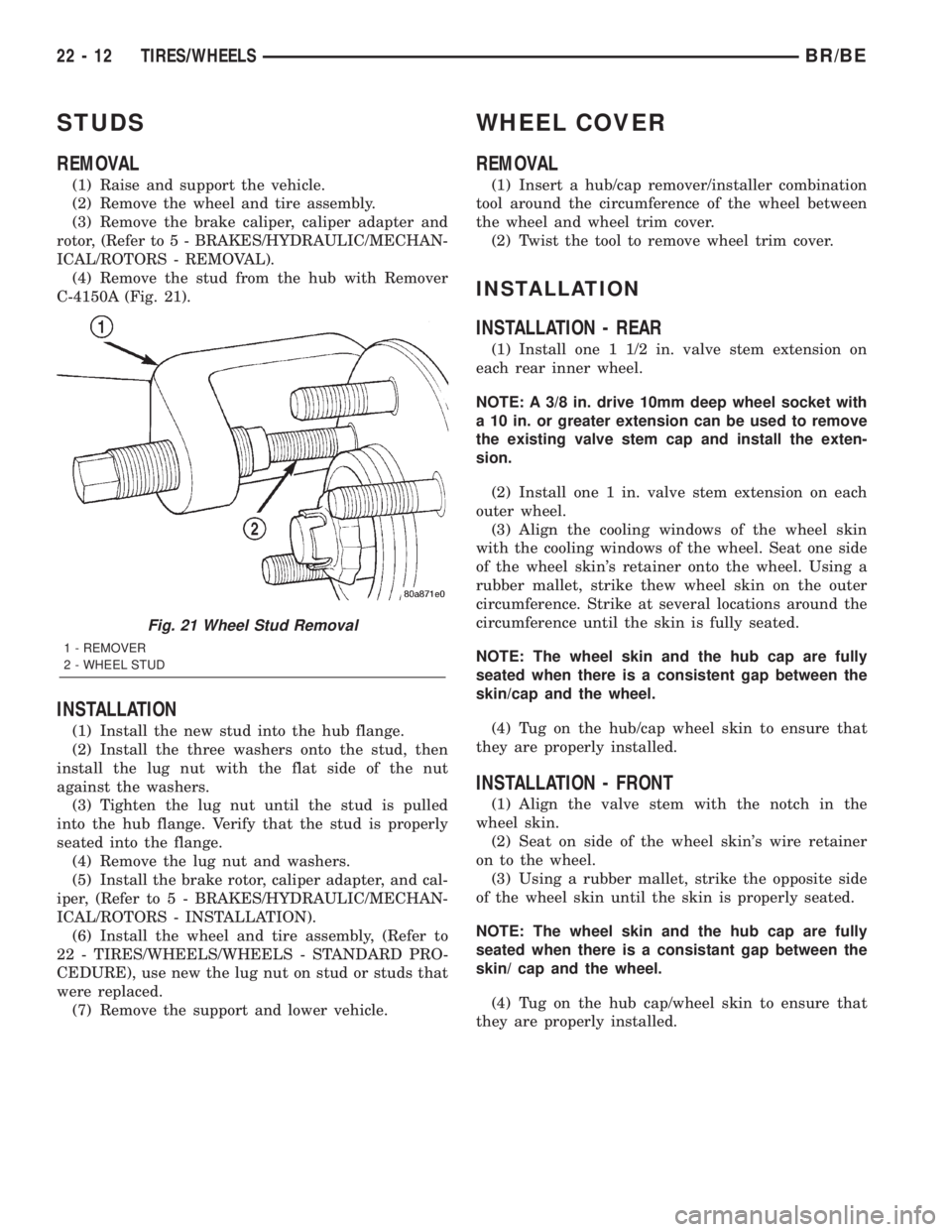
(4) Remove the stud from the hub with Remover
C-4150A (Fig. 21).
INSTALLATION
(1) Install the new stud into the hub flange.
(2) Install the three washers onto the stud, then
install the lug nut with the flat side of the nut
against the washers.
(3) Tighten the lug nut until the stud is pulled
into the hub flange. Verify that the stud is properly
seated into the flange.
(4) Remove the lug nut and washers.
(5) Install the brake rotor, caliper adapter, and cal-
iper, (Refer to 5 - BRAKES/HYDRAULIC/MECHAN-
ICAL/ROTORS - INSTALLATION).
(6) Install the wheel and tire assembly, (Refer to
22 - TIRES/WHEELS/WHEELS - STANDARD PRO-
CEDURE), use new the lug nut on stud or studs that
were replaced.
(7) Remove the support and lower vehicle.
WHEEL COVER
REMOVAL
(1) Insert a hub/cap remover/installer combination
tool around the circumference of the wheel between
the wheel and wheel trim cover.
(2) Twist the tool to remove wheel trim cover.
INSTALLATION
INSTALLATION - REAR
(1) Install one 1 1/2 in. valve stem extension on
each rear inner wheel.
NOTE: A 3/8 in. drive 10mm deep wheel socket with
a 10 in. or greater extension can be used to remove
the existing valve stem cap and install the exten-
sion.
(2) Install one 1 in. valve stem extension on each
outer wheel.
(3) Align the cooling windows of the wheel skin
with the cooling windows of the wheel. Seat one side
of the wheel skin's retainer onto the wheel. Using a
rubber mallet, strike thew wheel skin on the outer
circumference. Strike at several locations around the
circumference until the skin is fully seated.
NOTE: The wheel skin and the hub cap are fully
seated when there is a consistent gap between the
skin/cap and the wheel.
(4) Tug on the hub/cap wheel skin to ensure that
they are properly installed.
INSTALLATION - FRONT
(1) Align the valve stem with the notch in the
wheel skin.
(2) Seat on side of the wheel skin's wire retainer
on to the wheel.
(3) Using a rubber mallet, strike the opposite side
of the wheel skin until the skin is properly seated.
NOTE: The wheel skin and the hub cap are fully
seated when there is a consistant gap between the
skin/ cap and the wheel.
(4) Tug on the hub cap/wheel skin to ensure that
they are properly installed.
Fig. 21 Wheel Stud Removal
1 - REMOVER
2 - WHEEL STUD
22 - 12 TIRES/WHEELSBR/BE
Page 1996 of 2255
FRONT FENDER AND INNER WHEELHOUSE
BR/BEBODY 23 - 29
BODY (Continued)
Page 2053 of 2255
EXTERIOR
TABLE OF CONTENTS
page page
EXTERIOR
DESCRIPTION.........................86
OPERATION...........................86
BODY SIDE MOLDINGS
REMOVAL.............................86
INSTALLATION.........................87
BODY STRIPES AND DECALS
REMOVAL.............................87
INSTALLATION.........................87
TAPE STRIPE
REMOVAL.............................88
INSTALLATION.........................89
EXTERIOR NAME PLATES
REMOVAL.............................89
INSTALLATION.........................89
COWL GRILLE
REMOVAL.............................90
INSTALLATION.........................90
ROOF JOINT MOLDING
REMOVAL.............................91
INSTALLATION.........................91
GRILLE
REMOVAL.............................91
INSTALLATION.........................91
GRILLE FRAME
REMOVAL.............................91
INSTALLATION.........................92
FRONT END SPLASH SHIELDS
REMOVAL.............................92
INSTALLATION.........................92LEFT FRONT FENDER
REMOVAL.............................93
INSTALLATION.........................93
RIGHT FRONT FENDER
REMOVAL.............................94
INSTALLATION.........................94
FUEL FILL DOOR
REMOVAL.............................95
INSTALLATION.........................95
REAR FENDER
REMOVAL.............................95
INSTALLATION.........................95
REAR SPLASH SHIELD
REMOVAL.............................96
INSTALLATION.........................96
REAR WHEELHOUSE LINER
REMOVAL.............................96
INSTALLATION.........................96
CARGO BOX
REMOVAL.............................97
INSTALLATION.........................97
SIDE VIEW MIRROR
REMOVAL.............................97
INSTALLATION.........................98
SIDE VIEW MIRROR - LOW MOUNTED
REMOVAL.............................98
INSTALLATION.........................98
SIDE VIEW MIRROR GLASS
REMOVAL.............................98
INSTALLATION.........................98
EXTERIOR
DESCRIPTION
Exterior sheet metal components make up the
exterior of the vehicle. Some exterior metal systems
are welded assemblies, such as doors and hoods.
Some exterior trim items are made of composite.
OPERATION
The exterior is finished in various metal stampings
and composite moldings. These assemblies give the
vehicle a finished appearance and protect the occu-
pants from the elements. Some components are part
of the energy absorbing system used to protect the
occupants in collisions. The exterior sheet metal is
repairable and adjustable for fit and finish. Welded
and bonded component systems are adjustable as asystem. Trim components made of composite are
stamped with the type of material used.
DaimlerChrysler uses various fasteners to retain
trim items. At times, it is not possible to remove trim
items without damaging the fastener. If it is not pos-
sible to remove an item without damaging a compo-
nent, cut or break the fasteners and use new ones
when installing the component.BODY SIDE MOLDINGS
REMOVAL
(1) Warm the effected stick-on molding and body
metal to approximately 38ÉC (100ÉF) using a suitable
heat lamp or heat gun.
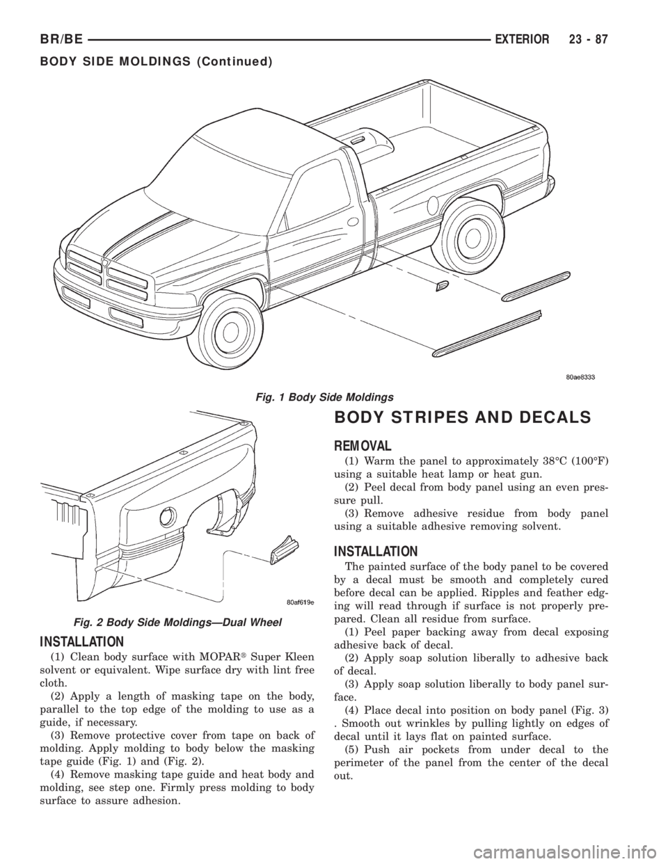
(2) Pull stick-on molding from painted surface
(Fig. 1) and (Fig. 2).
23 - 86 EXTERIORBR/BE
Page 2054 of 2255
INSTALLATION
(1) Clean body surface with MOPARtSuper Kleen
solvent or equivalent. Wipe surface dry with lint free
cloth.
(2) Apply a length of masking tape on the body,
parallel to the top edge of the molding to use as a
guide, if necessary.
(3) Remove protective cover from tape on back of
molding. Apply molding to body below the masking
tape guide (Fig. 1) and (Fig. 2).
(4) Remove masking tape guide and heat body and
molding, see step one. Firmly press molding to body
surface to assure adhesion.
BODY STRIPES AND DECALS
REMOVAL
(1) Warm the panel to approximately 38ÉC (100ÉF)
using a suitable heat lamp or heat gun.
(2) Peel decal from body panel using an even pres-
sure pull.
(3) Remove adhesive residue from body panel
using a suitable adhesive removing solvent.
INSTALLATION
The painted surface of the body panel to be covered
by a decal must be smooth and completely cured
before decal can be applied. Ripples and feather edg-
ing will read through if surface is not properly pre-
pared. Clean all residue from surface.
(1) Peel paper backing away from decal exposing
adhesive back of decal.
(2) Apply soap solution liberally to adhesive back
of decal.
(3) Apply soap solution liberally to body panel sur-
face.
(4) Place decal into position on body panel (Fig. 3)
. Smooth out wrinkles by pulling lightly on edges of
decal until it lays flat on painted surface.
(5) Push air pockets from under decal to the
perimeter of the panel from the center of the decal
out.
Fig. 1 Body Side Moldings
Fig. 2 Body Side MoldingsÐDual Wheel
BR/BEEXTERIOR 23 - 87
BODY SIDE MOLDINGS (Continued)
Page 2059 of 2255
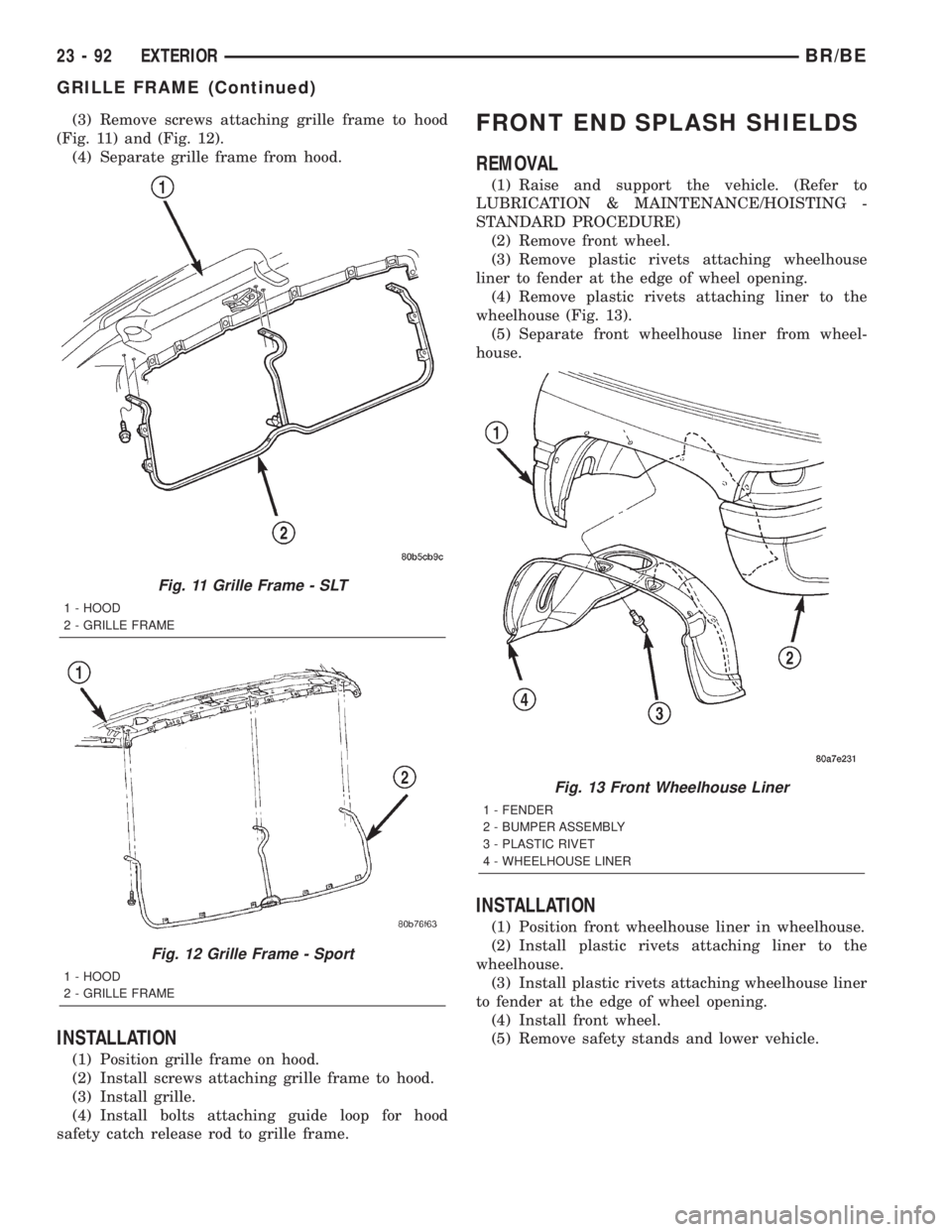
(3) Remove screws attaching grille frame to hood
(Fig. 11) and (Fig. 12).
(4) Separate grille frame from hood.
INSTALLATION
(1) Position grille frame on hood.
(2) Install screws attaching grille frame to hood.
(3) Install grille.
(4) Install bolts attaching guide loop for hood
safety catch release rod to grille frame.
FRONT END SPLASH SHIELDS
REMOVAL
(1) Raise and support the vehicle. (Refer to
LUBRICATION & MAINTENANCE/HOISTING -
STANDARD PROCEDURE)
(2) Remove front wheel.
(3) Remove plastic rivets attaching wheelhouse
liner to fender at the edge of wheel opening.
(4) Remove plastic rivets attaching liner to the
wheelhouse (Fig. 13).
(5) Separate front wheelhouse liner from wheel-
house.
INSTALLATION
(1) Position front wheelhouse liner in wheelhouse.
(2) Install plastic rivets attaching liner to the
wheelhouse.
(3) Install plastic rivets attaching wheelhouse liner
to fender at the edge of wheel opening.
(4) Install front wheel.
(5) Remove safety stands and lower vehicle.
Fig. 11 Grille Frame - SLT
1 - HOOD
2 - GRILLE FRAME
Fig. 12 Grille Frame - Sport
1 - HOOD
2 - GRILLE FRAME
Fig. 13 Front Wheelhouse Liner
1 - FENDER
2 - BUMPER ASSEMBLY
3 - PLASTIC RIVET
4 - WHEELHOUSE LINER
23 - 92 EXTERIORBR/BE
GRILLE FRAME (Continued)
Page 2060 of 2255
LEFT FRONT FENDER
REMOVAL
(1) Remove front bumper (Refer to 13 - FRAMES
& BUMPERS/BUMPERS/FRONT BUMPER -
REMOVAL).
(2) Remove air cleaner from wheelhouse (DIESEL
ONLY).
(3) Remove coolant overflow bottle (V-10 ONLY).
(4) Remove battery tray (Refer to 8 - ELECTRI-
CAL/BATTERY SYSTEM/TRAY - REMOVAL).
(5) Remove screws attaching power distribution
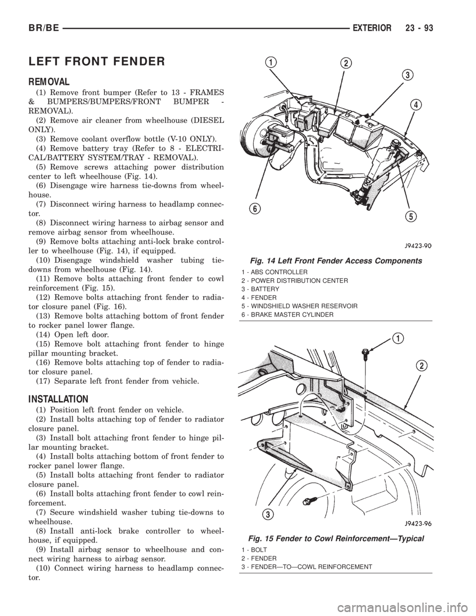
center to left wheelhouse (Fig. 14).
(6) Disengage wire harness tie-downs from wheel-
house.
(7) Disconnect wiring harness to headlamp connec-
tor.
(8) Disconnect wiring harness to airbag sensor and
remove airbag sensor from wheelhouse.
(9) Remove bolts attaching anti-lock brake control-
ler to wheelhouse (Fig. 14), if equipped.
(10) Disengage windshield washer tubing tie-
downs from wheelhouse (Fig. 14).
(11) Remove bolts attaching front fender to cowl
reinforcement (Fig. 15).
(12) Remove bolts attaching front fender to radia-
tor closure panel (Fig. 16).
(13) Remove bolts attaching bottom of front fender
to rocker panel lower flange.
(14) Open left door.
(15) Remove bolt attaching front fender to hinge
pillar mounting bracket.
(16) Remove bolts attaching top of fender to radia-
tor closure panel.
(17) Separate left front fender from vehicle.
INSTALLATION
(1) Position left front fender on vehicle.
(2) Install bolts attaching top of fender to radiator
closure panel.
(3) Install bolt attaching front fender to hinge pil-
lar mounting bracket.
(4) Install bolts attaching bottom of front fender to
rocker panel lower flange.
(5) Install bolts attaching front fender to radiator
closure panel.
(6) Install bolts attaching front fender to cowl rein-
forcement.
(7) Secure windshield washer tubing tie-downs to
wheelhouse.
(8) Install anti-lock brake controller to wheel-
house, if equipped.
(9) Install airbag sensor to wheelhouse and con-
nect wiring harness to airbag sensor.
(10) Connect wiring harness to headlamp connec-
tor.
Fig. 14 Left Front Fender Access Components
1 - ABS CONTROLLER
2 - POWER DISTRIBUTION CENTER
3 - BATTERY
4 - FENDER
5 - WINDSHIELD WASHER RESERVOIR
6 - BRAKE MASTER CYLINDER
Fig. 15 Fender to Cowl ReinforcementÐTypical
1 - BOLT
2 - FENDER
3 - FENDERÐTOÐCOWL REINFORCEMENT
BR/BEEXTERIOR 23 - 93