2002 DODGE RAM lock
[x] Cancel search: lockPage 1117 of 2255

INSTALLATION
(1) With engine raised SLIGHTLY, position the
engine support bracket/cushion and heat shields to
the block. Install new bolts and tighten to 81 N´m (60
ft. lbs.) torque.
(2) Install the through-bolt into the engine support
bracket/cushion.
(3) Lower engine with support/lifting fixture while
guiding the engine bracket/cushion and through-bolt
into support cushion brackets (Fig. 46) .
(4) Install through-bolt nuts and tighten the nuts
to 102 N´m (75 ft. lbs.) torque.
(5) Lower the vehicle.
(6) Remove lifting fixture.
REAR MOUNT
REMOVAL
(1) Raise the vehicle on a hoist.
(2) Position a transmission jack in place.
(3) Remove support cushion stud nuts (Fig. 47).
(4) Raise rear of transmission and engine
SLIGHTLY.
(5) Remove the bolts holding the support cushion
to the transmission support bracket. Remove the sup-
port cushion.
(6) If necessary, remove the bolts holding the
transmission support bracket to the transmission.
INSTALLATION
(1) If removed, position the transmission support
bracket to the transmission. Install new attaching
bolts and tighten to 88 N´m (65 ft. lbs.) torque.
(2) Position support cushion to transmission sup-
port bracket. Install stud nuts and tighten to 41 N´m
(30 ft. lbs.) torque.
(3) Using the transmission jack, lower the trans-
mission and support cushion onto the crossmember
(Fig. 47) .
(4) Install the support cushion bolts and tighten to
41 N´m (30 ft. lbs.) torque.
(5) Remove the transmission jack.
(6) Lower the vehicle.
LUBRICATION
DESCRIPTION
A gear-type positive displacement pump (Fig. 48) is
mounted at the underside of the rear main bearing
cap. The pump uses a pick-up tube and screen
assembly to gather engine oil from the oil pan.
OPERATION
The pump draws oil through the screen and inlet
tube from the sump at the rear of the oil pan. The oil
is driven between the drive and idler gears and
pump body, then forced through the outlet to the
block. An oil gallery in the block channels the oil to
the inlet side of the full flow oil filter. After passing
through the filter element, the oil passes from the
center outlet of the filter through an oil gallery that
channels the oil up to the main gallery, which
extends the entire length on the right side of the
block. The oil then goes down to the No. 1 main bear-
ing, back up to the left side of the block, and into the
oil gallery on the left side of the engine.
Galleries extend downward from the main oil gal-
lery to the upper shell of each main bearing. The
crankshaft is drilled internally to pass oil from the
main bearing journals to the connecting rod journals.
Each connecting rod bearing has half a hole in it, oil
passes through the hole when the rods rotate and the
hole lines up, oil is then thrown off as the rod
rotates. This oil throwoff lubricates the camshaft
lobes, distributor drive gear, cylinder walls, and pis-
ton pins.
The hydraulic valve tappets receive oil directly
from the main oil gallery. The camshaft bearings
receive oil from the main bearing galleries. The front
camshaft bearing journal passes oil through the cam-
shaft sprocket to the timing chain. Oil drains back to
the oil pan under the No. 1 main bearing cap.
The oil supply for the rocker arms and bridged
pivot assemblies is provided by the hydraulic valve
Fig. 46 Positioning Engine Front Mounts
1 - ENGINE SUPPORT BRACKET/CUSHION
2 - SUPPORT CUSHION BRACKET
9 - 42 ENGINE 5.9LBR/BE
FRONT MOUNT (Continued)
Page 1121 of 2255
stretching or other damage. Replace drain plug and
gasket if damaged.
(6) Install drain plug in crankcase.
(7) Change oil filter (Refer to 9 - ENGINE/LUBRI-
CATION/OIL FILTER - REMOVAL).
(8) Lower vehicle and fill crankcase with specified
type (Refer to LUBRICATION & MAINTENANCE/
FLUID TYPES - DESCRIPTION) and amount of
engine oil (Refer to LUBRICATION & MAINTE-
NANCE - SPECIFICATIONS).
(9) Install oil fill cap.
(10) Start engine and inspect for leaks.
(11) Stop engine and inspect oil level.
OIL FILTER
REMOVAL
All engines are equipped with a high quality full-
flow, disposable type oil filter. DaimlerChrysler Cor-
poration recommends a Mopartor equivalent oil
filter be used.
(1) Position a drain pan under the oil filter.
(2) Using a suitable oil filter wrench loosen filter.
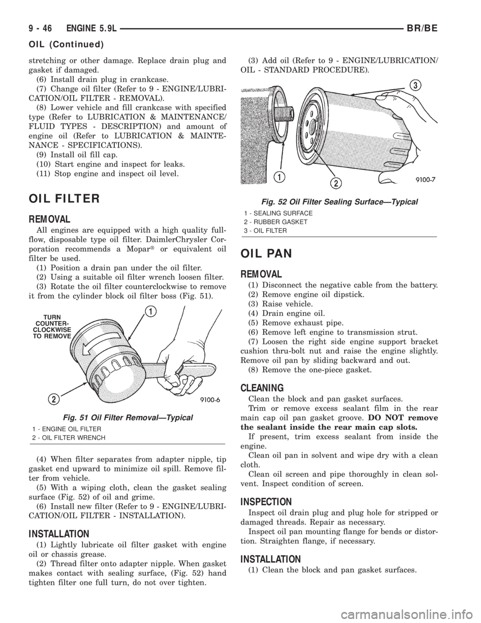
(3) Rotate the oil filter counterclockwise to remove
it from the cylinder block oil filter boss (Fig. 51).
(4) When filter separates from adapter nipple, tip
gasket end upward to minimize oil spill. Remove fil-
ter from vehicle.
(5) With a wiping cloth, clean the gasket sealing
surface (Fig. 52) of oil and grime.
(6) Install new filter (Refer to 9 - ENGINE/LUBRI-
CATION/OIL FILTER - INSTALLATION).
INSTALLATION
(1) Lightly lubricate oil filter gasket with engine
oil or chassis grease.
(2) Thread filter onto adapter nipple. When gasket
makes contact with sealing surface, (Fig. 52) hand
tighten filter one full turn, do not over tighten.(3) Add oil (Refer to 9 - ENGINE/LUBRICATION/
OIL - STANDARD PROCEDURE).
OIL PAN
REMOVAL
(1) Disconnect the negative cable from the battery.
(2) Remove engine oil dipstick.
(3) Raise vehicle.
(4) Drain engine oil.
(5) Remove exhaust pipe.
(6) Remove left engine to transmission strut.
(7) Loosen the right side engine support bracket
cushion thru-bolt nut and raise the engine slightly.
Remove oil pan by sliding backward and out.
(8) Remove the one-piece gasket.
CLEANING
Clean the block and pan gasket surfaces.
Trim or remove excess sealant film in the rear
main cap oil pan gasket groove.DO NOT remove
the sealant inside the rear main cap slots.
If present, trim excess sealant from inside the
engine.
Clean oil pan in solvent and wipe dry with a clean
cloth.
Clean oil screen and pipe thoroughly in clean sol-
vent. Inspect condition of screen.
INSPECTION
Inspect oil drain plug and plug hole for stripped or
damaged threads. Repair as necessary.
Inspect oil pan mounting flange for bends or distor-
tion. Straighten flange, if necessary.
INSTALLATION
(1) Clean the block and pan gasket surfaces.
Fig. 51 Oil Filter RemovalÐTypical
1 - ENGINE OIL FILTER
2 - OIL FILTER WRENCH
Fig. 52 Oil Filter Sealing SurfaceÐTypical
1 - SEALING SURFACE
2 - RUBBER GASKET
3 - OIL FILTER
9 - 46 ENGINE 5.9LBR/BE
OIL (Continued)
Page 1122 of 2255
(2) Trim or remove excess sealant film in the rear
main cap oil pan gasket groove.DO NOT remove
the sealant inside the rear main cap slots.
(3) If present, trim excess sealant from inside the
engine.
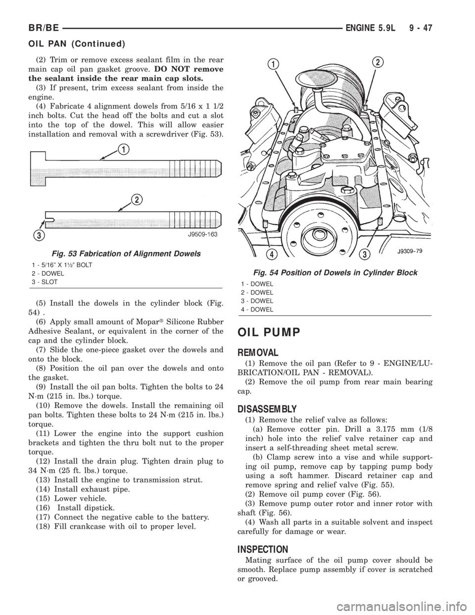
(4) Fabricate 4 alignment dowels from 5/16x11/2
inch bolts. Cut the head off the bolts and cut a slot
into the top of the dowel. This will allow easier
installation and removal with a screwdriver (Fig. 53).
(5) Install the dowels in the cylinder block (Fig.
54) .
(6) Apply small amount of MopartSilicone Rubber
Adhesive Sealant, or equivalent in the corner of the
cap and the cylinder block.
(7) Slide the one-piece gasket over the dowels and
onto the block.
(8) Position the oil pan over the dowels and onto
the gasket.
(9) Install the oil pan bolts. Tighten the bolts to 24
N´m (215 in. lbs.) torque.
(10) Remove the dowels. Install the remaining oil
pan bolts. Tighten these bolts to 24 N´m (215 in. lbs.)
torque.
(11) Lower the engine into the support cushion
brackets and tighten the thru bolt nut to the proper
torque.
(12) Install the drain plug. Tighten drain plug to
34 N´m (25 ft. lbs.) torque.
(13) Install the engine to transmission strut.
(14) Install exhaust pipe.
(15) Lower vehicle.
(16) Install dipstick.
(17) Connect the negative cable to the battery.
(18) Fill crankcase with oil to proper level.
OIL PUMP
REMOVAL
(1) Remove the oil pan (Refer to 9 - ENGINE/LU-
BRICATION/OIL PAN - REMOVAL).
(2) Remove the oil pump from rear main bearing
cap.
DISASSEMBLY
(1) Remove the relief valve as follows:
(a) Remove cotter pin. Drill a 3.175 mm (1/8
inch) hole into the relief valve retainer cap and
insert a self-threading sheet metal screw.
(b) Clamp screw into a vise and while support-
ing oil pump, remove cap by tapping pump body
using a soft hammer. Discard retainer cap and
remove spring and relief valve (Fig. 55).
(2) Remove oil pump cover (Fig. 56).
(3) Remove pump outer rotor and inner rotor with
shaft (Fig. 56).
(4) Wash all parts in a suitable solvent and inspect
carefully for damage or wear.
INSPECTION
Mating surface of the oil pump cover should be
smooth. Replace pump assembly if cover is scratched
or grooved.
Fig. 53 Fabrication of Alignment Dowels
1 - 5/16º X 1óº BOLT
2 - DOWEL
3 - SLOT
Fig. 54 Position of Dowels in Cylinder Block
1 - DOWEL
2 - DOWEL
3 - DOWEL
4 - DOWEL
BR/BEENGINE 5.9L 9 - 47
OIL PAN (Continued)
Page 1126 of 2255
(13) Disconnect the heater hoses and bypass hose.
(14) Remove the closed crankcase ventilation and
evaporation control systems.
(15) Remove intake manifold bolts.
(16) Lift the intake manifold and throttle body out
of the engine compartment as an assembly.
(17) Remove and discard the flange side gaskets
and the front and rear end seals.
(18) Remove the throttle body bolts and lift the
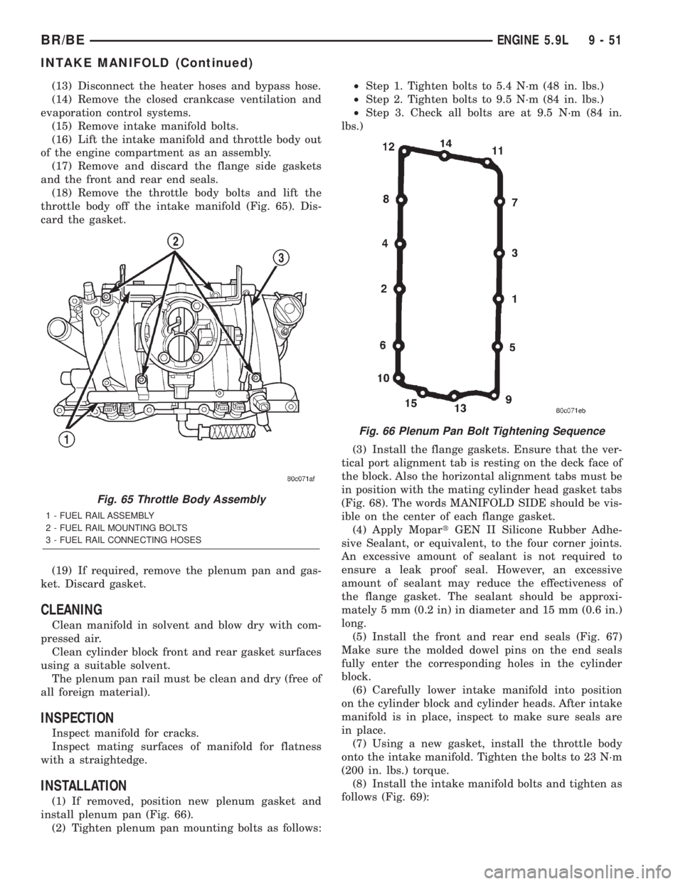
throttle body off the intake manifold (Fig. 65). Dis-
card the gasket.
(19) If required, remove the plenum pan and gas-
ket. Discard gasket.
CLEANING
Clean manifold in solvent and blow dry with com-
pressed air.
Clean cylinder block front and rear gasket surfaces
using a suitable solvent.
The plenum pan rail must be clean and dry (free of
all foreign material).
INSPECTION
Inspect manifold for cracks.
Inspect mating surfaces of manifold for flatness
with a straightedge.
INSTALLATION
(1) If removed, position new plenum gasket and
install plenum pan (Fig. 66).
(2) Tighten plenum pan mounting bolts as follows:²Step 1. Tighten bolts to 5.4 N´m (48 in. lbs.)
²Step 2. Tighten bolts to 9.5 N´m (84 in. lbs.)
²Step 3. Check all bolts are at 9.5 N´m (84 in.
lbs.)
(3) Install the flange gaskets. Ensure that the ver-
tical port alignment tab is resting on the deck face of
the block. Also the horizontal alignment tabs must be
in position with the mating cylinder head gasket tabs
(Fig. 68). The words MANIFOLD SIDE should be vis-
ible on the center of each flange gasket.
(4) Apply MopartGEN II Silicone Rubber Adhe-
sive Sealant, or equivalent, to the four corner joints.
An excessive amount of sealant is not required to
ensure a leak proof seal. However, an excessive
amount of sealant may reduce the effectiveness of
the flange gasket. The sealant should be approxi-
mately 5 mm (0.2 in) in diameter and 15 mm (0.6 in.)
long.
(5) Install the front and rear end seals (Fig. 67)
Make sure the molded dowel pins on the end seals
fully enter the corresponding holes in the cylinder
block.
(6) Carefully lower intake manifold into position
on the cylinder block and cylinder heads. After intake
manifold is in place, inspect to make sure seals are
in place.
(7) Using a new gasket, install the throttle body
onto the intake manifold. Tighten the bolts to 23 N´m
(200 in. lbs.) torque.
(8) Install the intake manifold bolts and tighten as
follows (Fig. 69):
Fig. 65 Throttle Body Assembly
1 - FUEL RAIL ASSEMBLY
2 - FUEL RAIL MOUNTING BOLTS
3 - FUEL RAIL CONNECTING HOSES
Fig. 66 Plenum Pan Bolt Tightening Sequence
BR/BEENGINE 5.9L 9 - 51
INTAKE MANIFOLD (Continued)
Page 1129 of 2255
(3) Remove power steering pump (Refer to 19 -
STEERING/PUMP - REMOVAL).
(4) Remove vibration damper (Refer to 9 -
ENGINE/ENGINE BLOCK/VIBRATION DAMPER -
REMOVAL).
(5) Loosen oil pan bolts and remove the front bolt
at each side.
(6) Remove the cover bolts.
(7) Remove chain case cover and gasket using
extreme caution to avoid damaging oil pan gasket.
INSTALLATION
(1) Be sure mating surfaces of chain case cover
and cylinder block are clean and free from burrs.
(2) The water pump mounting surface must be
cleaned.
(3) Using a new cover gasket, carefully install
chain case cover to avoid damaging oil pan gasket.
Use a small amount of MopartSilicone Rubber Adhe-
sive Sealant, or equivalent, at the joint between tim-
ing chain cover gasket and the oil pan gasket. Finger
tighten the timing chain cover bolts at this time.
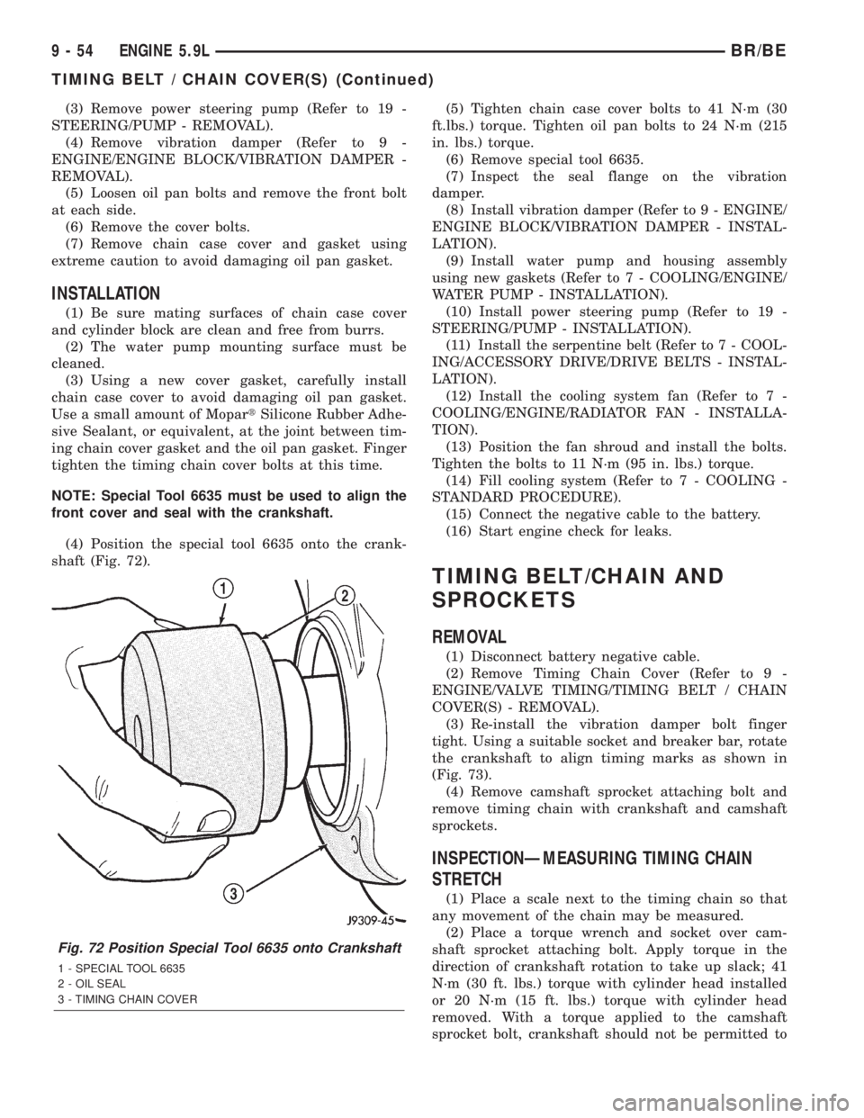
NOTE: Special Tool 6635 must be used to align the
front cover and seal with the crankshaft.
(4) Position the special tool 6635 onto the crank-
shaft (Fig. 72).(5) Tighten chain case cover bolts to 41 N´m (30
ft.lbs.) torque. Tighten oil pan bolts to 24 N´m (215
in. lbs.) torque.
(6) Remove special tool 6635.
(7) Inspect the seal flange on the vibration
damper.
(8) Install vibration damper (Refer to 9 - ENGINE/
ENGINE BLOCK/VIBRATION DAMPER - INSTAL-
LATION).
(9) Install water pump and housing assembly
using new gaskets (Refer to 7 - COOLING/ENGINE/
WATER PUMP - INSTALLATION).
(10) Install power steering pump (Refer to 19 -
STEERING/PUMP - INSTALLATION).
(11) Install the serpentine belt (Refer to 7 - COOL-
ING/ACCESSORY DRIVE/DRIVE BELTS - INSTAL-
LATION).
(12) Install the cooling system fan (Refer to 7 -
COOLING/ENGINE/RADIATOR FAN - INSTALLA-
TION).
(13) Position the fan shroud and install the bolts.
Tighten the bolts to 11 N´m (95 in. lbs.) torque.
(14) Fill cooling system (Refer to 7 - COOLING -
STANDARD PROCEDURE).
(15) Connect the negative cable to the battery.
(16) Start engine check for leaks.
TIMING BELT/CHAIN AND
SPROCKETS
REMOVAL
(1) Disconnect battery negative cable.
(2) Remove Timing Chain Cover (Refer to 9 -
ENGINE/VALVE TIMING/TIMING BELT / CHAIN
COVER(S) - REMOVAL).
(3) Re-install the vibration damper bolt finger
tight. Using a suitable socket and breaker bar, rotate
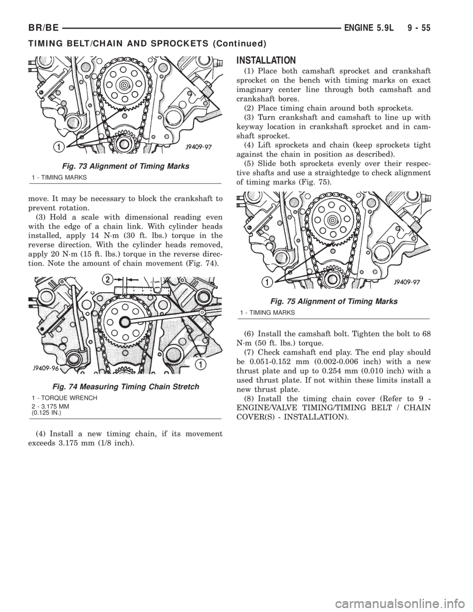
the crankshaft to align timing marks as shown in
(Fig. 73).
(4) Remove camshaft sprocket attaching bolt and
remove timing chain with crankshaft and camshaft
sprockets.
INSPECTIONÐMEASURING TIMING CHAIN
STRETCH
(1) Place a scale next to the timing chain so that
any movement of the chain may be measured.
(2) Place a torque wrench and socket over cam-
shaft sprocket attaching bolt. Apply torque in the
direction of crankshaft rotation to take up slack; 41
N´m (30 ft. lbs.) torque with cylinder head installed
or 20 N´m (15 ft. lbs.) torque with cylinder head
removed. With a torque applied to the camshaft
sprocket bolt, crankshaft should not be permitted to
Fig. 72 Position Special Tool 6635 onto Crankshaft
1 - SPECIAL TOOL 6635
2 - OIL SEAL
3 - TIMING CHAIN COVER
9 - 54 ENGINE 5.9LBR/BE
TIMING BELT / CHAIN COVER(S) (Continued)
Page 1130 of 2255
move. It may be necessary to block the crankshaft to
prevent rotation.
(3) Hold a scale with dimensional reading even
with the edge of a chain link. With cylinder heads
installed, apply 14 N´m (30 ft. lbs.) torque in the
reverse direction. With the cylinder heads removed,
apply 20 N´m (15 ft. lbs.) torque in the reverse direc-
tion. Note the amount of chain movement (Fig. 74).
(4) Install a new timing chain, if its movement
exceeds 3.175 mm (1/8 inch).
INSTALLATION
(1) Place both camshaft sprocket and crankshaft
sprocket on the bench with timing marks on exact
imaginary center line through both camshaft and
crankshaft bores.
(2) Place timing chain around both sprockets.
(3) Turn crankshaft and camshaft to line up with
keyway location in crankshaft sprocket and in cam-
shaft sprocket.
(4) Lift sprockets and chain (keep sprockets tight
against the chain in position as described).
(5) Slide both sprockets evenly over their respec-
tive shafts and use a straightedge to check alignment
of timing marks (Fig. 75).
(6) Install the camshaft bolt. Tighten the bolt to 68
N´m (50 ft. lbs.) torque.
(7) Check camshaft end play. The end play should
be 0.051-0.152 mm (0.002-0.006 inch) with a new
thrust plate and up to 0.254 mm (0.010 inch) with a
used thrust plate. If not within these limits install a
new thrust plate.
(8) Install the timing chain cover (Refer to 9 -
ENGINE/VALVE TIMING/TIMING BELT / CHAIN
COVER(S) - INSTALLATION).
Fig. 73 Alignment of Timing Marks
1 - TIMING MARKS
Fig. 74 Measuring Timing Chain Stretch
1 - TORQUE WRENCH
2 - 3.175 MM
(0.125 IN.)
Fig. 75 Alignment of Timing Marks
1 - TIMING MARKS
BR/BEENGINE 5.9L 9 - 55
TIMING BELT/CHAIN AND SPROCKETS (Continued)
Page 1131 of 2255
ENGINE 8.0L
TABLE OF CONTENTS
page page
ENGINE 8.0L
DESCRIPTION.........................58
DIAGNOSIS AND TESTING
DIAGNOSIS AND TESTING - ENGINE
DIAGNOSIS - INTRODUCTION...........58
DIAGNOSIS AND TESTINGÐENGINE
DIAGNOSIS - PERFORMANCE...........59
DIAGNOSIS AND TESTINGÐ ENGINE
DIAGNOSIS - MECHANICAL.............61
DIAGNOSIS AND TESTINGÐENGINE
DIAGNOSIS - LUBRICATION.............63
DIAGNOSIS AND TESTINGÐCYLINDER
COMPRESSION PRESSURE.............64
DIAGNOSIS AND TESTING - CYLINDER
COMBUSTION PRESSURE LEAKAGE......64
STANDARD PROCEDURE
STANDARD PROCEDUREÐCYLINDER
BORE HONING.......................65
STANDARD PROCEDURE - FORM-IN-
PLACE GASKETS AND SEALERS.........66
STANDARD PROCEDURE - REPAIR
DAMAGED OR WORN THREADS.........66
STANDARD PROCEDUREÐHYDROSTATIC
LOCK...............................66
REMOVAL.............................67
INSTALLATION.........................68
SPECIFICATIONS
8.OL ENGINE........................68
TORQUE............................71
SPECIAL TOOLS
8.0L ENGINE.........................72
AIR CLEANER ELEMENT
REMOVAL - 8.0L........................75
INSTALLATION - 8.0L....................75
CYLINDER HEAD
DESCRIPTION.........................76
DIAGNOSIS AND TESTINGÐCYLINDER HEAD
GASKET FAILURE.....................76
REMOVAL.............................76
CLEANING............................77
INSPECTION..........................77
INSTALLATION.........................77
CYLINDER HEAD COVER(S)
DESCRIPTION.........................78
REMOVAL.............................78
CLEANING............................79
INSPECTION..........................79
INSTALLATION.........................79INTAKE/EXHAUST VALVES & SEATS
DESCRIPTION.........................80
STANDARD PROCEDURE
VALVE SERVICE......................80
REMOVAL
REMOVALÐVALVE STEM SEALS.........82
REMOVALÐVALVES AND VALVE SPRINGS . 82
CLEANING............................83
INSPECTION..........................83
INSTALLATION
INSTALLATIONÐVALVE STEM SEAL......83
INSTALLATIONÐVALVES AND VALVE
SPRINGS............................84
ROCKER ARM / ADJUSTER ASSY
REMOVAL.............................84
INSTALLATION.........................84
ENGINE BLOCK
CLEANING............................85
INSPECTION..........................85
CAMSHAFT & BEARINGS (IN BLOCK)
REMOVAL
REMOVALÐCAMSHAFT BEARINGS.......85
REMOVALÐCAMSHAFT................85
INSTALLATION
INSTALLATIONÐCAMSHAFT BEARINGS . . . 86
INSTALLATIONÐCAMSHAFT............86
CONNECTING ROD BEARINGS
STANDARD PROCEDURE - CONNECTING
ROD BEARING FITTING................87
CRANKSHAFT
REMOVAL.............................87
INSTALLATION.........................88
CRANKSHAFT MAIN BEARINGS
STANDARD PROCEDUREÐFITTING
CRANKSHAFT MAIN BEARINGS..........88
REMOVAL.............................88
INSTALLATION.........................88
CRANKSHAFT OIL SEAL - FRONT
REMOVAL
REMOVALÐFRONT OIL SEAL - FRONT
COVER INSTALLED....................89
REMOVALÐFRONT OIL SEAL - FRONT
COVER REMOVED....................89
INSTALLATION
INSTALLATIONÐFRONT OIL SEAL ± FRONT
COVER INSTALLED....................89
INSTALLATIONÐFRONT OIL SEAL - FRONT
COVER REMOVED....................90
9 - 56 ENGINE 8.0LBR/BE
Page 1133 of 2255
ENGINE 8.0L
DESCRIPTION
The 8.0 Liter (488 CID) ten-cylinder engine is a
V-Type lightweight, single cam, overhead valve
engine with hydraulic roller tappets. This engine is
designed for unleaded fuel.
Engine lubrication system consists of a gerotor
type oil pump mounted in the timing chain cover and
driven by the crankshaft. The V-10 uses a full flow
oil filter.
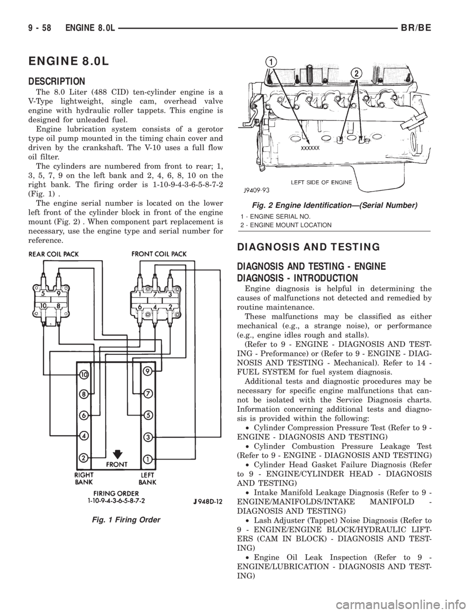
The cylinders are numbered from front to rear; 1,
3, 5, 7, 9 on the left bank and 2, 4, 6, 8, 10 on the
right bank. The firing order is 1-10-9-4-3-6-5-8-7-2
(Fig. 1) .
The engine serial number is located on the lower
left front of the cylinder block in front of the engine
mount (Fig. 2) . When component part replacement is
necessary, use the engine type and serial number for
reference.
DIAGNOSIS AND TESTING
DIAGNOSIS AND TESTING - ENGINE
DIAGNOSIS - INTRODUCTION
Engine diagnosis is helpful in determining the
causes of malfunctions not detected and remedied by
routine maintenance.
These malfunctions may be classified as either
mechanical (e.g., a strange noise), or performance
(e.g., engine idles rough and stalls).
(Refer to 9 - ENGINE - DIAGNOSIS AND TEST-
ING - Preformance) or (Refer to 9 - ENGINE - DIAG-
NOSIS AND TESTING - Mechanical). Refer to 14 -
FUEL SYSTEM for fuel system diagnosis.
Additional tests and diagnostic procedures may be
necessary for specific engine malfunctions that can-
not be isolated with the Service Diagnosis charts.
Information concerning additional tests and diagno-
sis is provided within the following:
²Cylinder Compression Pressure Test (Refer to 9 -
ENGINE - DIAGNOSIS AND TESTING)
²Cylinder Combustion Pressure Leakage Test
(Refer to 9 - ENGINE - DIAGNOSIS AND TESTING)
²Cylinder Head Gasket Failure Diagnosis (Refer
to 9 - ENGINE/CYLINDER HEAD - DIAGNOSIS
AND TESTING)
²Intake Manifold Leakage Diagnosis (Refer to 9 -
ENGINE/MANIFOLDS/INTAKE MANIFOLD -
DIAGNOSIS AND TESTING)
²Lash Adjuster (Tappet) Noise Diagnosis (Refer to
9 - ENGINE/ENGINE BLOCK/HYDRAULIC LIFT-
ERS (CAM IN BLOCK) - DIAGNOSIS AND TEST-
ING)
²Engine Oil Leak Inspection (Refer to 9 -
ENGINE/LUBRICATION - DIAGNOSIS AND TEST-
ING)
Fig. 1 Firing Order
Fig. 2 Engine IdentificationÐ(Serial Number)
1 - ENGINE SERIAL NO.
2 - ENGINE MOUNT LOCATION
9 - 58 ENGINE 8.0LBR/BE