2002 DODGE RAM engine oil
[x] Cancel search: engine oilPage 1583 of 2255
(a) Loosen locknut on each band adjusting screw
4-5 turns.
(b) Tighten both adjusting screws to 8 N´m (72
in. lbs.).
(c) Back off front band adjusting screw 2-7/8
turns.
(d) Back off rear band adjusting screw 2 turns.
(e) Hold each adjusting screw in position and
tighten locknut to 34 N´m (25 ft. lbs.) torque.
(2) Install magnet in oil pan. Magnet seats on
small protrusion at corner of pan.
(3) Position new oil pan gasket on case and install
oil pan. Tighten pan bolts to 13.6 N´m (125 in. lbs.).
(4) Install throttle valve and shift selector levers
on valve body manual lever shaft.
(5) Apply small quantity of dielectric grease to ter-
minal pins of solenoid case connector and neutral
switch.
(6) Fill transmission with recommended fluid.
Refer to Service Procedures section of this group.
INSTALLATION
(1) Check torque converter hub and hub drive
notches for sharp edges burrs, scratches, or nicks.
Polish the hub and notches with 320/400 grit paper
and crocus cloth if necessary. The hub must be
smooth to avoid damaging pump seal at installation.
(2) Lubricate pocket in the rear oil pump seal lip
with transmission fluid.(3) Lubricate converter pilot hub of the crankshaft
with a light coating of MopartHigh Temp Grease.
(4) Align and install converter in oil pump.
(5) Carefully insert converter in oil pump. Then
rotate converter back and forth until fully seated in
pump gears.
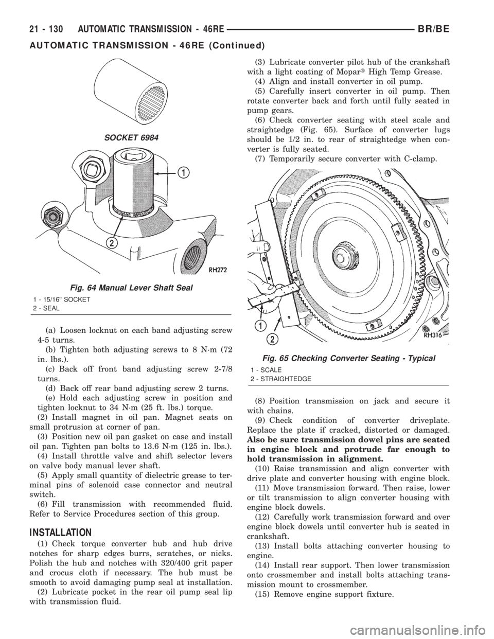
(6) Check converter seating with steel scale and
straightedge (Fig. 65). Surface of converter lugs
should be 1/2 in. to rear of straightedge when con-
verter is fully seated.
(7) Temporarily secure converter with C-clamp.
(8) Position transmission on jack and secure it
with chains.
(9) Check condition of converter driveplate.
Replace the plate if cracked, distorted or damaged.
Also be sure transmission dowel pins are seated
in engine block and protrude far enough to
hold transmission in alignment.
(10) Raise transmission and align converter with
drive plate and converter housing with engine block.
(11) Move transmission forward. Then raise, lower
or tilt transmission to align converter housing with
engine block dowels.
(12) Carefully work transmission forward and over
engine block dowels until converter hub is seated in
crankshaft.
(13) Install bolts attaching converter housing to
engine.
(14) Install rear support. Then lower transmission
onto crossmember and install bolts attaching trans-
mission mount to crossmember.
(15) Remove engine support fixture.
SOCKET 6984
Fig. 64 Manual Lever Shaft Seal
1 - 15/16©© SOCKET
2 - SEAL
Fig. 65 Checking Converter Seating - Typical
1 - SCALE
2 - STRAIGHTEDGE
21 - 130 AUTOMATIC TRANSMISSION - 46REBR/BE
AUTOMATIC TRANSMISSION - 46RE (Continued)
Page 1599 of 2255
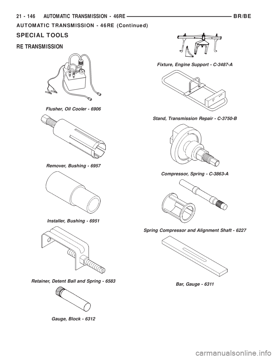
SPECIAL TOOLS
RE TRANSMISSION
Flusher, Oil Cooler - 6906
Remover, Bushing - 6957
Installer, Bushing - 6951
Retainer, Detent Ball and Spring - 6583
Gauge, Block - 6312
Fixture, Engine Support - C-3487-A
Stand, Transmission Repair - C-3750-B
Compressor, Spring - C-3863-A
Spring Compressor and Alignment Shaft - 6227
Bar, Gauge - 6311
21 - 146 AUTOMATIC TRANSMISSION - 46REBR/BE
AUTOMATIC TRANSMISSION - 46RE (Continued)
Page 1606 of 2255
GOVERNOR PRESSURE CURVES
There are four governor pressure curves pro-
grammed into the transmission control module. The
different curves allow the control module to adjust
governor pressure for varying conditions. One curve
is used for operation when fluid temperature is at, or
below, ±1ÉC (30ÉF). A second curve is used when fluid
temperature is at, or above, 10ÉC (50ÉF) during nor-
mal city or highway driving. A third curve is used
during wide-open throttle operation. The fourth curve
is used when driving with the transfer case in low
range.
OPERATION
Compensation is required for performance varia-
tions of two of the input devices. Though the slope of
the transfer functions is tightly controlled, offset may
vary due to various environmental factors or manu-
facturing tolerances.
The pressure transducer is affected by barometric
pressure as well as temperature. Calibration of the
zero pressure offset is required to compensate for
shifting output due to these factors.
Normal calibration will be performed when sump
temperature is above 50 degrees F, or in the absence
of sump temperature data, after the first 10 minutes
of vehicle operation. Calibration of the pressure
transducer offset occurs each time the output shaft
speed falls below 200 RPM. Calibration shall be
repeated each 3 seconds the output shaft speed is
below 200 RPM. A 0.5 second pulse of 95% duty cycle
is applied to the governor pressure solenoid valve
and the transducer output is read during this pulse.
Averaging of the transducer signal is necessary to
reject electrical noise.
Under cold conditions (below 50 degrees F sump),
the governor pressure solenoid valve response may
be too slow to guarantee 0 psi during the 0.5 second
calibration pulse. Calibration pulses are continued
during this period, however the transducer output
valves are discarded. Transducer offset must be read
at key-on, under conditions which promote a stable
reading. This value is retained and becomes the off-
set during the9cold9period of operation.
GOVERNOR PRESSURE SOLENOID VALVE
The inlet side of the solenoid valve is exposed to
normal transmission line pressure. The outlet side of
the valve leads to the valve body governor circuit.
The solenoid valve regulates line pressure to pro-
duce governor pressure. The average current sup-
plied to the solenoid controls governor pressure. One
amp current produces zero kPa/psi governor pres-
sure. Zero amps sets the maximum governor pres-
sure.The powertrain control module (PCM) turns on the
trans control relay which supplies electrical power to
the solenoid valve. Operating voltage is 12 volts
(DC). The PCM controls the ground side of the sole-
noid using the governor pressure solenoid control cir-
cuit.
GOVERNOR PRESSURE SENSOR
The sensor output signal provides the necessary
feedback to the PCM. This feedback is needed to ade-
quately control governor pressure.
GOVERNOR BODY AND TRANSFER PLATE
The transfer plate channels line pressure to the
solenoid valve through the governor body. It also
channels governor pressure from the solenoid valve
to the governor circuit. It is the solenoid valve that
develops the necessary governor pressure.
GOVERNOR PRESSURE CURVES
LOW TRANSMISSION FLUID TEMPERATURE
When the transmission fluid is cold the conven-
tional governor can delay shifts, resulting in higher
than normal shift speeds and harsh shifts. The elec-
tronically controlled low temperature governor pres-
sure curve is higher than normal to make the
transmission shift at normal speeds and sooner. The
PCM uses a temperature sensor in the transmission
oil sump to determine when low temperature gover-
nor pressure is needed.
NORMAL OPERATION
Normal operation is refined through the increased
computing power of the PCM and through access to
data on engine operating conditions provided by the
PCM that were not available with the previous
stand-alone electronic module. This facilitated the
development of a load adaptive shift strategy - the
ability to alter the shift schedule in response to vehi-
cle load condition. One manifestation of this capabil-
ity is grade9hunting9prevention - the ability of the
transmission logic to delay an upshift on a grade if
the engine does not have sufficient power to main-
tain speed in the higher gear. The 3-2 downshift and
the potential for hunting between gears occurs with a
heavily loaded vehicle or on steep grades. When
hunting occurs, it is very objectionable because shifts
are frequent and accompanied by large changes in
noise and acceleration.
WIDE OPEN THROTTLE OPERATION
In wide-open throttle (WOT) mode, adaptive mem-
ory in the PCM assures that up-shifts occur at the
preprogrammed optimum speed. WOT operation is
determined from the throttle position sensor, which
is also a part of the emission control system. The ini-
BR/BEAUTOMATIC TRANSMISSION - 46RE 21 - 153
ELECTRONIC GOVERNOR (Continued)
Page 1611 of 2255
In either case, air bubbles can cause overheating
and/or fluid oxidation, and varnishing. This can
interfere with normal valve, clutch, and accumulator
operation. Foaming can also result in fluid escaping
from the transmission vent where it may be mis-
taken for a leak.
Along with fluid level, it is important to check the
condition of the fluid. When the fluid smells burned,
and is contaminated with metal or friction material
particles, a complete transmission recondition is
needed. Be sure to examine the fluid on the dipstick
closely. If there is any doubt about its condition,
drain out a sample for a double check.
After the fluid has been checked, seat the dipstick
fully to seal out water and dirt.
The transmission has a dipstick to check oil level.
It is located on the right side of the engine. Be sure
to wipe all dirt from dipstick handle before removing.
Fluid level is checked with the engine running at
curb idle speed, the transmission in NEUTRAL and
the transmission fluid at normal operating tempera-
ture.The engine should be running at idle
speed for at least one minute, with the vehicle
on level ground.
The transmission fluid level can be checked two
ways.
PROCEDURE ONE
(1) Transmission fluid must be at normal operat-
ing temperature for accurate fluid level check. Drive
vehicle if necessary to bring fluid temperature up to
normal hot operating temperature of 82ÉC (180ÉF).
(2) Position vehicle on level surface.
(3) Start and run engine at curb idle speed.
(4) Apply parking brakes.
(5) Shift transmission momentarily into all gear
ranges. Then shift transmission back to NEUTRAL.
(6) Clean top of filler tube and dipstick to keep
dirt from entering tube.
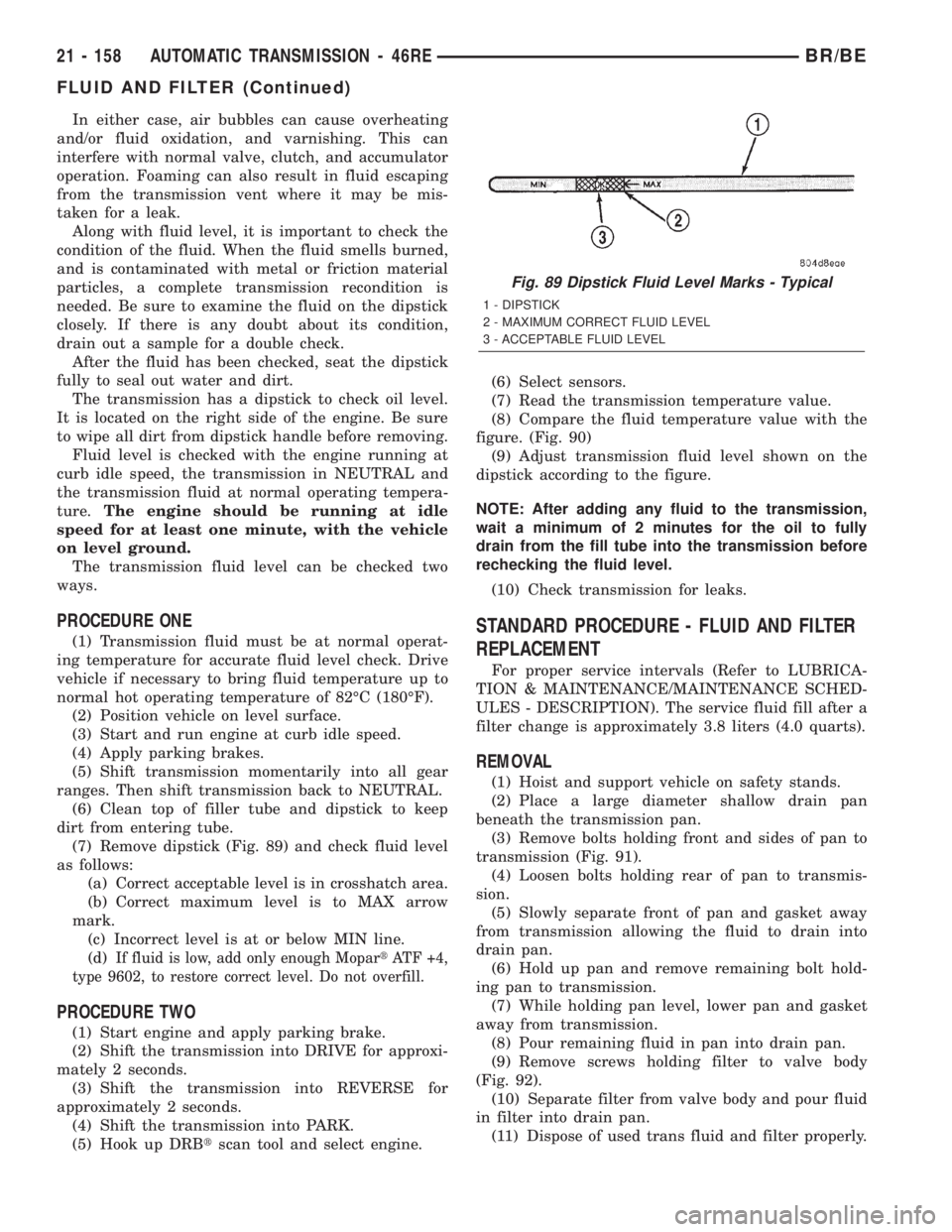
(7) Remove dipstick (Fig. 89) and check fluid level
as follows:
(a) Correct acceptable level is in crosshatch area.
(b) Correct maximum level is to MAX arrow
mark.
(c) Incorrect level is at or below MIN line.
(d)
If fluid is low, add only enough MopartATF +4,
type 9602, to restore correct level. Do not overfill.
PROCEDURE TWO
(1) Start engine and apply parking brake.
(2) Shift the transmission into DRIVE for approxi-
mately 2 seconds.
(3) Shift the transmission into REVERSE for
approximately 2 seconds.
(4) Shift the transmission into PARK.
(5) Hook up DRBtscan tool and select engine.(6) Select sensors.
(7) Read the transmission temperature value.
(8) Compare the fluid temperature value with the
figure. (Fig. 90)
(9) Adjust transmission fluid level shown on the
dipstick according to the figure.
NOTE: After adding any fluid to the transmission,
wait a minimum of 2 minutes for the oil to fully
drain from the fill tube into the transmission before
rechecking the fluid level.
(10) Check transmission for leaks.
STANDARD PROCEDURE - FLUID AND FILTER
REPLACEMENT
For proper service intervals (Refer to LUBRICA-
TION & MAINTENANCE/MAINTENANCE SCHED-
ULES - DESCRIPTION). The service fluid fill after a
filter change is approximately 3.8 liters (4.0 quarts).
REMOVAL
(1) Hoist and support vehicle on safety stands.
(2) Place a large diameter shallow drain pan
beneath the transmission pan.
(3) Remove bolts holding front and sides of pan to
transmission (Fig. 91).
(4) Loosen bolts holding rear of pan to transmis-
sion.
(5) Slowly separate front of pan and gasket away
from transmission allowing the fluid to drain into
drain pan.
(6) Hold up pan and remove remaining bolt hold-
ing pan to transmission.
(7) While holding pan level, lower pan and gasket
away from transmission.
(8) Pour remaining fluid in pan into drain pan.
(9) Remove screws holding filter to valve body
(Fig. 92).
(10) Separate filter from valve body and pour fluid
in filter into drain pan.
(11) Dispose of used trans fluid and filter properly.
Fig. 89 Dipstick Fluid Level Marks - Typical
1 - DIPSTICK
2 - MAXIMUM CORRECT FLUID LEVEL
3 - ACCEPTABLE FLUID LEVEL
21 - 158 AUTOMATIC TRANSMISSION - 46REBR/BE
FLUID AND FILTER (Continued)
Page 1613 of 2255
INSTALLATION
(1) Position a new transmission oil filter onto the
valve body.
(2) Install the screws to hold the filter to the valve
body. Tighten the screws to 4 N´m (35 in.lbs.).
(3) Clean the gasket surfaces of the transmission
oil pan and transmission pan rail.
NOTE: The transmission pan oil gasket is reusable.
Inspect the sealing surfaces of the gasket. If the
sealing ribs on both surfaces appear to be in good
condition, clean the gasket of any foreign material
and reinstall.
(4) Position the oil pan gasket onto the oil pan.
(5) Position the oil pan and gasket onto the trans-
mission and install several bolts to hold the pan and
gasket to the transmission.
(6) Install the remainder of the oil pan bolts.
Tighten the bolts to 13.6 N´m (125 in.lbs.).
(7) Lower vehicle and fill transmission. (Refer to
21 - TRANSMISSION/TRANSAXLE/AUTOMATIC/
FLUID - STANDARD PROCEDURE)
STANDARD PROCEDURE - TRANSMISSION
FILL
To avoid overfilling transmission after a fluid
change or overhaul, perform the following procedure:
(1) Remove dipstick and insert clean funnel in
transmission fill tube.
(2) Add following initial quantity of MopartAT F
+4, type 9602, to transmission:
(a) If only fluid and filter were changed, add3
pints (1-1/2 quarts)of ATF +4 to transmission.
(b) If transmission was completely overhauled,
torque converter was replaced or drained, and
cooler was flushed, add12 pints (6 quarts)of ATF
+4 to transmission.
(3) Apply parking brakes.
(4) Start and run engine at normal curb idle
speed.
(5) Apply service brakes, shift transmission
through all gear ranges then back to NEUTRAL, set
parking brake, and leave engine running at curb idle
speed.
(6) Remove funnel, insert dipstick and check fluid
level. If level is low,add fluid to bring level to
MIN mark on dipstick.Check to see if the oil level
is equal on both sides of the dipstick. If one side is
noticably higher than the other, the dipstick has
picked up some oil from the dipstick tube. Allow the
oil to drain down the dipstick tube and re-check.
(7) Drive vehicle until transmission fluid is at nor-
mal operating temperature.(8) With the engine running at curb idle speed, the
gear selector in NEUTRAL, and the parking brake
applied, check the transmission fluid level.
CAUTION: Do not overfill transmission, fluid foam-
ing and shifting problems can result.
(9) Add fluid to bring level up to MAX arrow
mark.
When fluid level is correct, shut engine off, release
park brake, remove funnel, and install dipstick in fill
tube.
FRONT CLUTCH
DESCRIPTION
The front clutch assembly (Fig. 93) is composed of
the front clutch retainer, pressure plate, clutch
plates, driving discs, piston, piston return spring,
return spring retainer, and snap-rings. The front
clutch is the forward-most component in the trans-
mission geartrain and is directly behind the oil pump
and is considered a driving component.
NOTE: The number of discs and plates may vary
with each engine and vehicle combination.
OPERATION
To apply the clutch, pressure is applied between
the clutch retainer and piston. The fluid pressure is
provided by the oil pump, transferred through the
control valves and passageways, and enters the
clutch through the hub of the reaction shaft support.
With pressure applied between the clutch retainer
and piston, the piston moves away from the clutch
retainer and compresses the clutch pack. This action
applies the clutch pack, allowing torque to flow
through the input shaft into the driving discs, and
into the clutch plates and pressure plate that are
lugged to the clutch retainer. The waved snap-ring is
used to cushion the application of the clutch pack.
When pressure is released from the piston, the
spring returns the piston to its fully released position
and disengages the clutch. The release spring also
helps to cushion the application of the clutch assem-
bly. When the clutch is in the process of being
released by the release spring, fluid flows through a
vent and one-way ball-check-valve located in the
clutch retainer. The check-valve is needed to elimi-
nate the possibility of plate drag caused by centrifu-
gal force acting on the residual fluid trapped in the
clutch piston retainer.
21 - 160 AUTOMATIC TRANSMISSION - 46REBR/BE
FLUID AND FILTER (Continued)
Page 1617 of 2255
FRONT SERVO
DESCRIPTION
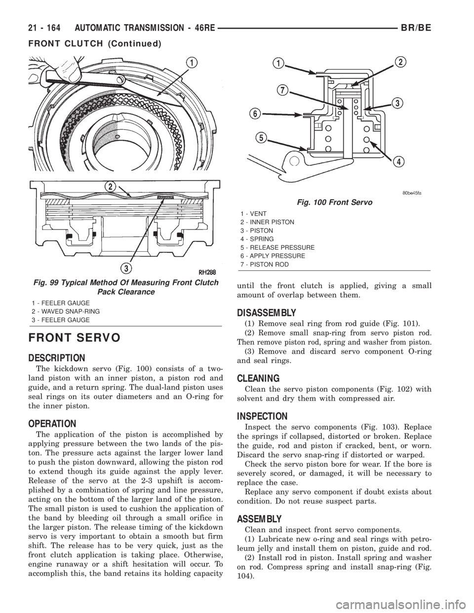
The kickdown servo (Fig. 100) consists of a two-
land piston with an inner piston, a piston rod and
guide, and a return spring. The dual-land piston uses
seal rings on its outer diameters and an O-ring for
the inner piston.
OPERATION
The application of the piston is accomplished by
applying pressure between the two lands of the pis-
ton. The pressure acts against the larger lower land
to push the piston downward, allowing the piston rod
to extend though its guide against the apply lever.
Release of the servo at the 2-3 upshift is accom-
plished by a combination of spring and line pressure,
acting on the bottom of the larger land of the piston.
The small piston is used to cushion the application of
the band by bleeding oil through a small orifice in
the larger piston. The release timing of the kickdown
servo is very important to obtain a smooth but firm
shift. The release has to be very quick, just as the
front clutch application is taking place. Otherwise,
engine runaway or a shift hesitation will occur. To
accomplish this, the band retains its holding capacityuntil the front clutch is applied, giving a small
amount of overlap between them.
DISASSEMBLY
(1) Remove seal ring from rod guide (Fig. 101).
(2)
Remove small snap-ring from servo piston rod.
Then remove piston rod, spring and washer from piston.
(3) Remove and discard servo component O-ring
and seal rings.
CLEANING
Clean the servo piston components (Fig. 102) with
solvent and dry them with compressed air.
INSPECTION
Inspect the servo components (Fig. 103). Replace
the springs if collapsed, distorted or broken. Replace
the guide, rod and piston if cracked, bent, or worn.
Discard the servo snap-ring if distorted or warped.
Check the servo piston bore for wear. If the bore is
severely scored, or damaged, it will be necessary to
replace the case.
Replace any servo component if doubt exists about
condition. Do not reuse suspect parts.
ASSEMBLY
Clean and inspect front servo components.
(1) Lubricate new o-ring and seal rings with petro-
leum jelly and install them on piston, guide and rod.
(2) Install rod in piston. Install spring and washer
on rod. Compress spring and install snap-ring (Fig.
104).
Fig. 99 Typical Method Of Measuring Front Clutch
Pack Clearance
1 - FEELER GAUGE
2 - WAVED SNAP-RING
3 - FEELER GAUGE
Fig. 100 Front Servo
1 - VENT
2 - INNER PISTON
3 - PISTON
4 - SPRING
5 - RELEASE PRESSURE
6 - APPLY PRESSURE
7 - PISTON ROD
21 - 164 AUTOMATIC TRANSMISSION - 46REBR/BE
FRONT CLUTCH (Continued)
Page 1620 of 2255
(2) Run the engineat curb idle speed, with the
shift selector in neutral.
(3) If one quart of transmission fluid is collected in
the container in 20 seconds or less, oil pump flow vol-
ume is within acceptable limits. If fluid flow is inter-
mittent, or it takes more than 20 seconds to collect
one quart of fluid, refer to the Hydraulic Pressure
tests in this section for further diagnosis.
(4) Re-connect theTo coolerline to the transmis-
sion cooler inlet.
(5) Refill the transmission to proper level.
DISASSEMBLY
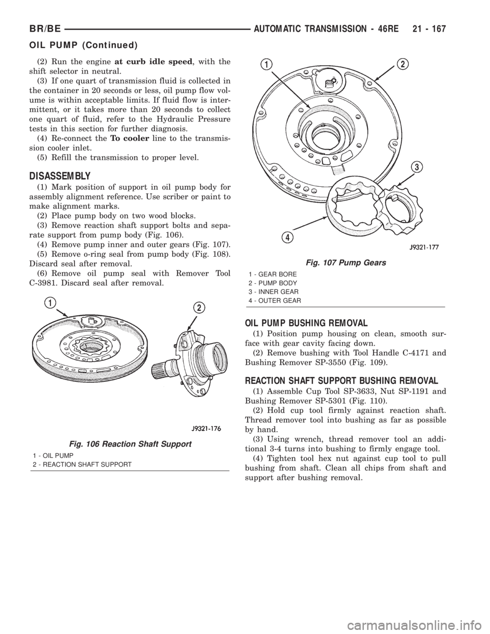
(1) Mark position of support in oil pump body for
assembly alignment reference. Use scriber or paint to
make alignment marks.
(2) Place pump body on two wood blocks.
(3) Remove reaction shaft support bolts and sepa-
rate support from pump body (Fig. 106).
(4) Remove pump inner and outer gears (Fig. 107).
(5) Remove o-ring seal from pump body (Fig. 108).
Discard seal after removal.
(6) Remove oil pump seal with Remover Tool
C-3981. Discard seal after removal.
OIL PUMP BUSHING REMOVAL
(1) Position pump housing on clean, smooth sur-
face with gear cavity facing down.
(2) Remove bushing with Tool Handle C-4171 and
Bushing Remover SP-3550 (Fig. 109).
REACTION SHAFT SUPPORT BUSHING REMOVAL
(1) Assemble Cup Tool SP-3633, Nut SP-1191 and
Bushing Remover SP-5301 (Fig. 110).
(2) Hold cup tool firmly against reaction shaft.
Thread remover tool into bushing as far as possible
by hand.
(3) Using wrench, thread remover tool an addi-
tional 3-4 turns into bushing to firmly engage tool.
(4) Tighten tool hex nut against cup tool to pull
bushing from shaft. Clean all chips from shaft and
support after bushing removal.
Fig. 106 Reaction Shaft Support
1 - OIL PUMP
2 - REACTION SHAFT SUPPORT
Fig. 107 Pump Gears
1 - GEAR BORE
2 - PUMP BODY
3 - INNER GEAR
4 - OUTER GEAR
BR/BEAUTOMATIC TRANSMISSION - 46RE 21 - 167
OIL PUMP (Continued)
Page 1625 of 2255
INSTALLATION
(1) Place replacement bearing in position in hous-
ing.
(2) Using a suitable driver, drive bearing into
housing until the snap-ring groove is visible.
(3) Install snap-ring to hold bearing into housing
(Fig. 117).
(4) Install overdrive geartrain into housing.
(5) Install overdrive unit in vehicle.
OVERDRIVE CLUTCH
DESCRIPTION
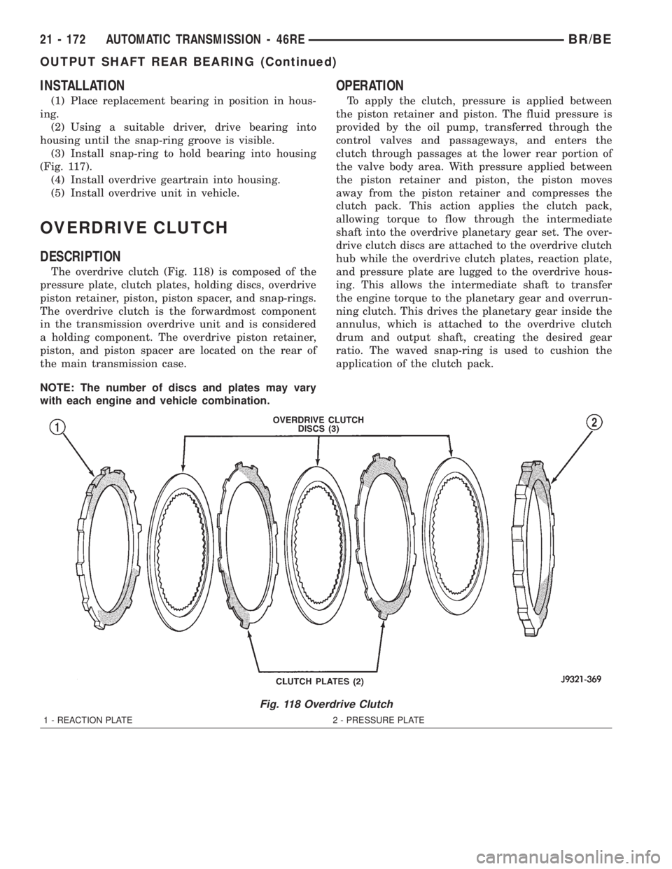
The overdrive clutch (Fig. 118) is composed of the
pressure plate, clutch plates, holding discs, overdrive
piston retainer, piston, piston spacer, and snap-rings.
The overdrive clutch is the forwardmost component
in the transmission overdrive unit and is considered
a holding component. The overdrive piston retainer,
piston, and piston spacer are located on the rear of
the main transmission case.
NOTE: The number of discs and plates may vary
with each engine and vehicle combination.
OPERATION
To apply the clutch, pressure is applied between
the piston retainer and piston. The fluid pressure is
provided by the oil pump, transferred through the
control valves and passageways, and enters the
clutch through passages at the lower rear portion of
the valve body area. With pressure applied between
the piston retainer and piston, the piston moves
away from the piston retainer and compresses the
clutch pack. This action applies the clutch pack,
allowing torque to flow through the intermediate
shaft into the overdrive planetary gear set. The over-
drive clutch discs are attached to the overdrive clutch
hub while the overdrive clutch plates, reaction plate,
and pressure plate are lugged to the overdrive hous-
ing. This allows the intermediate shaft to transfer
the engine torque to the planetary gear and overrun-
ning clutch. This drives the planetary gear inside the
annulus, which is attached to the overdrive clutch
drum and output shaft, creating the desired gear
ratio. The waved snap-ring is used to cushion the
application of the clutch pack.
Fig. 118 Overdrive Clutch
1 - REACTION PLATE 2 - PRESSURE PLATE
21 - 172 AUTOMATIC TRANSMISSION - 46REBR/BE
OUTPUT SHAFT REAR BEARING (Continued)