2002 DODGE RAM timing belt
[x] Cancel search: timing beltPage 1179 of 2255
OIL PUMP
REMOVAL
(1) Remove the timing chain cover (Refer to 9 -
ENGINE/VALVE TIMING/TIMING BELT / CHAIN
COVER(S) - REMOVAL).
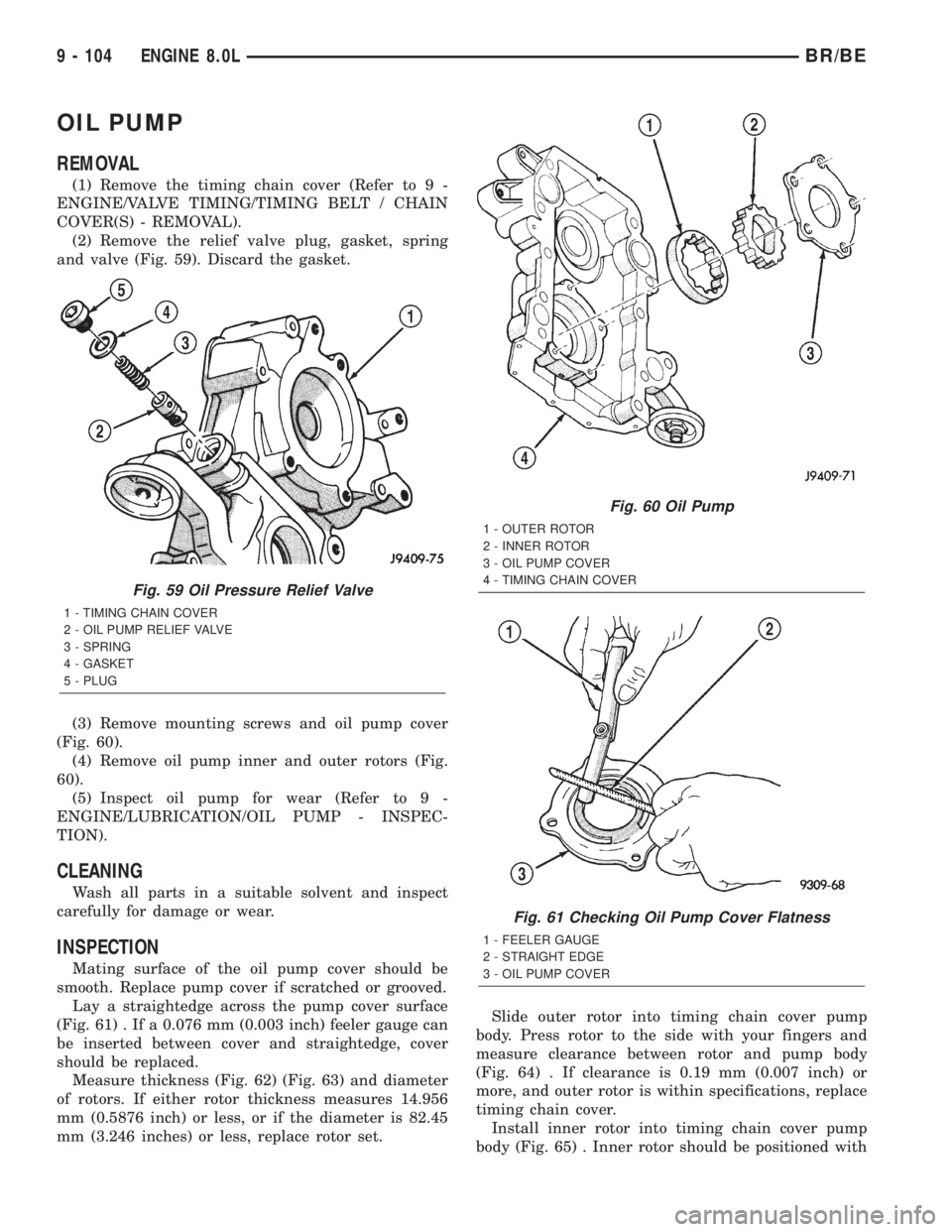
(2) Remove the relief valve plug, gasket, spring
and valve (Fig. 59). Discard the gasket.
(3) Remove mounting screws and oil pump cover
(Fig. 60).
(4) Remove oil pump inner and outer rotors (Fig.
60).
(5) Inspect oil pump for wear (Refer to 9 -
ENGINE/LUBRICATION/OIL PUMP - INSPEC-
TION).
CLEANING
Wash all parts in a suitable solvent and inspect
carefully for damage or wear.
INSPECTION
Mating surface of the oil pump cover should be
smooth. Replace pump cover if scratched or grooved.
Lay a straightedge across the pump cover surface
(Fig. 61) . If a 0.076 mm (0.003 inch) feeler gauge can
be inserted between cover and straightedge, cover
should be replaced.
Measure thickness (Fig. 62) (Fig. 63) and diameter
of rotors. If either rotor thickness measures 14.956
mm (0.5876 inch) or less, or if the diameter is 82.45
mm (3.246 inches) or less, replace rotor set.Slide outer rotor into timing chain cover pump
body. Press rotor to the side with your fingers and
measure clearance between rotor and pump body
(Fig. 64) . If clearance is 0.19 mm (0.007 inch) or
more, and outer rotor is within specifications, replace
timing chain cover.
Install inner rotor into timing chain cover pump
body (Fig. 65) . Inner rotor should be positioned with
Fig. 59 Oil Pressure Relief Valve
1 - TIMING CHAIN COVER
2 - OIL PUMP RELIEF VALVE
3 - SPRING
4 - GASKET
5 - PLUG
Fig. 60 Oil Pump
1 - OUTER ROTOR
2 - INNER ROTOR
3 - OIL PUMP COVER
4 - TIMING CHAIN COVER
Fig. 61 Checking Oil Pump Cover Flatness
1 - FEELER GAUGE
2 - STRAIGHT EDGE
3 - OIL PUMP COVER
9 - 104 ENGINE 8.0LBR/BE
Page 1181 of 2255
when compressed to 34 mm (1-11/32 inches). Replace
spring that fails to meet these specifications.
If oil pressure was low and pump is within specifi-
cations, inspect for worn engine bearings or other
reasons for oil pressure loss.
INSTALLATION
(1) Lubricate both oil pump rotors using petroleum
jelly or lubriplate and install in the timing chain
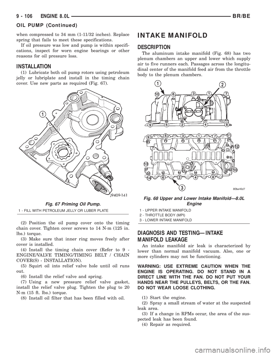
cover. Use new parts as required (Fig. 67).
(2) Position the oil pump cover onto the timing
chain cover. Tighten cover screws to 14 N´m (125 in.
lbs.) torque.
(3) Make sure that inner ring moves freely after
cover is installed.
(4) Install the timing chain cover (Refer to 9 -
ENGINE/VALVE TIMING/TIMING BELT / CHAIN
COVER(S) - INSTALLATION).
(5) Squirt oil into relief valve hole until oil runs
out.
(6) Install the relief valve and spring.
(7) Using a new pressure relief valve gasket,
install the relief valve plug. Tighten the plug to 20
N´m (15 ft. lbs.) torque.
(8) Install oil filter that has been filled with oil.
INTAKE MANIFOLD
DESCRIPTION
The aluminum intake manifold (Fig. 68) has two
plenum chambers an upper and lower which supply
air to five runners each. Passages across the longitu-
dinal center of the manifold feed air from the throttle
body to the plenum chambers.
DIAGNOSIS AND TESTINGÐINTAKE
MANIFOLD LEAKAGE
An intake manifold air leak is characterized by
lower than normal manifold vacuum. Also, one or
more cylinders may not be functioning.
WARNING: USE EXTREME CAUTION WHEN THE
ENGINE IS OPERATING. DO NOT STAND IN A
DIRECT LINE WITH THE FAN. DO NOT PUT YOUR
HANDS NEAR THE PULLEYS, BELTS, OR THE FAN.
DO NOT WEAR LOOSE CLOTHING.
(1) Start the engine.
(2) Spray a small stream of water at the suspected
leak area.
(3) If a change in RPMs occur, the area of the sus-
pected leak has been found.
(4) Repair as required.
Fig. 67 Priming Oil Pump.
1 - FILL WITH PETROLEUM JELLY OR LUBER PLATE
Fig. 68 Upper and Lower Intake ManifoldÐ8.0L
Engine
1 - UPPER INTAKE MANIFOLD
2 - THROTTLE BODY (MPI)
3 - LOWER INTAKE MANIFOLD
9 - 106 ENGINE 8.0LBR/BE
OIL PUMP (Continued)
Page 1185 of 2255
(2) Install the dipstick bracket on to the exhaust
manifold (right side only).
(3) Position washers and exhaust heat shields onto
the manifold stud bolts (Fig. 76). Be sure the tabs on
the heat shields are hooked over the top of the
exhaust gasket. Install the nuts and tighten to 20
N´m (175 in. lbs.) torque.
(4) Raise and support the vehicle.
(5) Assemble exhaust pipe to manifold.
(6) Lower the vehicle.
(7) Connect the negative cable to the battery.
(8) Start engine check for leaks.
TIMING BELT / CHAIN
COVER(S)
REMOVAL
(1) Disconnect the negative cable from the battery.
(2) Drain cooling system (Refer to 7 - COOLING -
STANDARD PROCEDURE).
(3) Remove the serpentine belt (Refer to 7 - COOL-
ING/ACCESSORY DRIVE/DRIVE BELTS - REMOV-
AL).
(4) Remove fan and fan shroud (Refer to 7 -
COOLING/ENGINE/RADIATOR FAN - REMOVAL).
(5) Unbolt A/C compressor and set on top of
engine.
(6) Remove generator, air pump, and bracket
assembly.
(7) Remove water pump (Refer to 7 - COOLING/
ENGINE/WATER PUMP - REMOVAL).
(8) Remove damper bolt and washer.
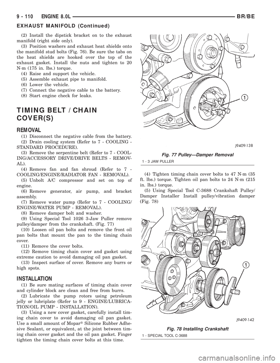
(9) Using Special Tool 1026 3-Jaw Puller remove
pulley/damper from the crankshaft. (Fig. 77)
(10) Loosen oil pan bolts and remove the front oil
pan bolts that mount the pan to the timing chain
cover.
(11) Remove the cover bolts.
(12) Remove timing chain cover and gasket using
extreme caution to avoid damaging oil pan gasket.
(13) Inspect surface of cover. Remove any burrs or
high spots.
INSTALLATION
(1) Be sure mating surfaces of timing chain cover
and cylinder block are clean and free from burrs.
(2) Lubricate the pump rotors using petroleum
jelly or lubriplate (Refer to 9 - ENGINE/LUBRICA-
TION/OIL PUMP - INSTALLATION).
(3) Using a new cover gasket, carefully install tim-
ing chain cover to avoid damaging oil pan gasket.
Use a small amount of MopartSilicone Rubber Adhe-
sive Sealant, or equivalent, at the joint between tim-
ing chain cover gasket and the oil pan gasket. Finger
tighten the timing chain cover bolts at this time.(4) Tighten timing chain cover bolts to 47 N´m (35
ft. lbs.) torque. Tighten oil pan bolts to 24 N´m (215
in. lbs.) torque.
(5) Using Special Tool C-3688 Crankshaft Pulley/
Damper Installer Install pulley/vibration damper
(Fig. 78)
Fig. 77 PulleyÐDamper Removal
1-3JAWPULLER
Fig. 78 Installing Crankshaft
1 - SPECIAL TOOL C-3688
9 - 110 ENGINE 8.0LBR/BE
EXHAUST MANIFOLD (Continued)
Page 1186 of 2255
(6) Prime oil pump by squirting oil in the oil filter
mounting hole and filling the J-trap of the front tim-
ing cover. When oil is running out, install oil filter
that has been filled with oil.
(7) Install water pump and housing assembly
using new o-ring (Refer to 7 - COOLING/ENGINE/
WATER PUMP - INSTALLATION).
(8) Install generator, air pump, and bracket assem-
bly.
(9) Install A/C compressor (Refer to 24 - HEATING
& AIR CONDITIONING/PLUMBING/A/C COM-
PRESSOR - INSTALLATION).
(10) (10) Install the radiator fan (Refer to 7 -
COOLING/ENGINE/RADIATOR FAN - INSTALLA-
TION).
(11) Position the fan shroud and install the bolts.
Tighten the bolts to 11 N´m (95 in. lbs.) torque.
(12) Install the serpentine belt (Refer to 7 - COOL-
ING/ACCESSORY DRIVE/DRIVE BELTS - INSTAL-
LATION).
(13) Fill cooling system (Refer to 7 - COOLING -
STANDARD PROCEDURE).
(14) Connect the negative cable to the battery.
(15) Road test vehicle and check for leaks.
TIMING BELT/CHAIN AND
SPROCKETS
REMOVAL
(1) Remove timing chain cover and gasket using
extreme caution to avoid damaging oil pan gasket
(Refer to 9 - ENGINE/VALVE TIMING/TIMING
BELT / CHAIN COVER(S) - REMOVAL).
(2) Aline camshaft and crankshaft centerline.
Remove camshaft sprocket attaching bolt and remove
timing chain and camshaft sprockets.
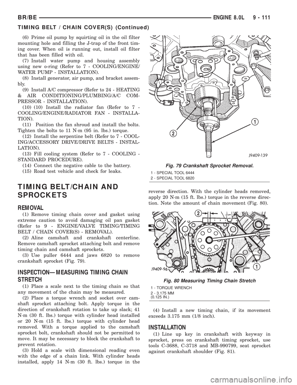
(3) Use puller 6444 and jaws 6820 to remove
crankshaft sprocket (Fig. 79).
INSPECTIONÐMEASURING TIMING CHAIN
STRETCH
(1) Place a scale next to the timing chain so that
any movement of the chain may be measured.
(2) Place a torque wrench and socket over cam-
shaft sprocket attaching bolt. Apply torque in the
direction of crankshaft rotation to take up slack; 41
N´m (30 ft. lbs.) torque with cylinder head installed
or 20 N´m (15 ft. lbs.) torque with cylinder head
removed. With a torque applied to the camshaft
sprocket bolt, crankshaft should not be permitted to
move. It may be necessary to block the crankshaft to
prevent rotation.
(3) Hold a scale with dimensional reading even
with the edge of a chain link. With cylinder heads
installed, apply 14 N´m (30 ft. lbs.) torque in thereverse direction. With the cylinder heads removed,
apply 20 N´m (15 ft. lbs.) torque in the reverse direc-
tion. Note the amount of chain movement (Fig. 80).
(4) Install a new timing chain, if its movement
exceeds 3.175 mm (1/8 inch).
INSTALLATION
(1) Line up key in crankshaft with keyway in
sprocket, press on crankshaft timing sprocket, use
tools C-3688, C-3718 and MB-990799, seat sprocket
against crankshaft shoulder (Fig. 81).
Fig. 79 Crankshaft Sprocket Removal.
1 - SPECIAL TOOL 6444
2 - SPECIAL TOOL 6820
Fig. 80 Measuring Timing Chain Stretch
1 - TORQUE WRENCH
2 - 3.175 MM
(0.125 IN.)
BR/BEENGINE 8.0L 9 - 111
TIMING BELT / CHAIN COVER(S) (Continued)
Page 1187 of 2255
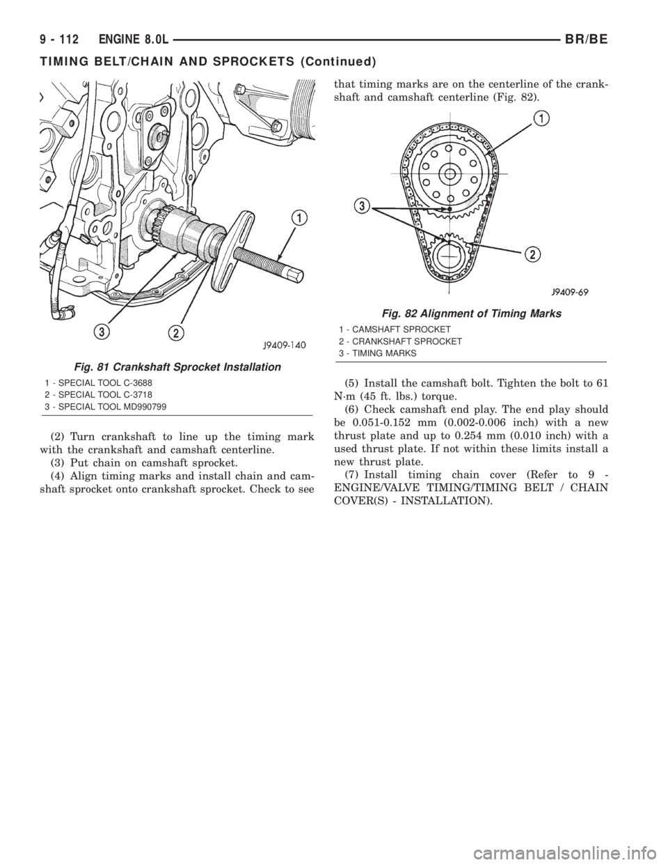
(2) Turn crankshaft to line up the timing mark
with the crankshaft and camshaft centerline.
(3) Put chain on camshaft sprocket.
(4) Align timing marks and install chain and cam-
shaft sprocket onto crankshaft sprocket. Check to seethat timing marks are on the centerline of the crank-
shaft and camshaft centerline (Fig. 82).
(5) Install the camshaft bolt. Tighten the bolt to 61
N´m (45 ft. lbs.) torque.
(6) Check camshaft end play. The end play should
be 0.051-0.152 mm (0.002-0.006 inch) with a new
thrust plate and up to 0.254 mm (0.010 inch) with a
used thrust plate. If not within these limits install a
new thrust plate.
(7) Install timing chain cover (Refer to 9 -
ENGINE/VALVE TIMING/TIMING BELT / CHAIN
COVER(S) - INSTALLATION).
Fig. 81 Crankshaft Sprocket Installation
1 - SPECIAL TOOL C-3688
2 - SPECIAL TOOL C-3718
3 - SPECIAL TOOL MD990799
Fig. 82 Alignment of Timing Marks
1 - CAMSHAFT SPROCKET
2 - CRANKSHAFT SPROCKET
3 - TIMING MARKS
9 - 112 ENGINE 8.0LBR/BE
TIMING BELT/CHAIN AND SPROCKETS (Continued)
Page 1233 of 2255
(11) Install the cylinder head cover and reusable
gasket (Fig. 85) (Refer to 9 - ENGINE/CYLINDER
HEAD/CYLINDER HEAD COVER(S) - INSTALLA-
TION).
(12) Install gear housing cover (Refer to 9 -
ENGINE/VALVE TIMING/GEAR HOUSING COVER
- INSTALLATION).
(13) Install the crankshaft damper (Fig. 83) (Refer
to 9 - ENGINE/ENGINE BLOCK/VIBRATION
DAMPER - INSTALLATION).
(14) Install the fan support/hub assembly (Fig. 82)
and tighten bolts to 24 N´m (18 ft. lbs.) torque.
(15) Install the crankcase breather housing (Refer
to 9 - ENGINE - INSTALLATION).
(16) Install the charge air cooler (with a/c con-
denser and auxiliary transmission oil cooler, if
equipped) and tighten the mounting bolts to 2 N´m
(17 in. lbs.) torque.
(17) Connect charge air cooler inlet and outlet
pipes. Tighten clamps to 10 N´m (100 in. lbs.) torque.
(18) Install the radiator upper support panel.
(19) Close radiator petcock and lower the radiator
into the engine compartment. Tighten the mounting
bolts to 11 N´m (95 in. lbs.) torque.
(20) Raise vehicle on hoist.
(21) Connect radiator lower hose and install
clamp.
(22) Connect transmission auxiliary oil cooler lines
(if equipped).
(23) Lower vehicle.
(24) Install the fan shroud and tighten the mount-
ing screws to 6 N´m (50 in. lbs.) torque.
(25) Install the viscous fan/drive assembly (Refer
to 7 - COOLING/ENGINE/RADIATOR FAN -
INSTALLATION).
(26) Install the coolant recovery and windshield
washer fluid reservoirs to the fan shroud.
(27) Connect the coolant recovery hose to the radi-
ator filler neck.
(28) Install the accessory drive belt (Refer to 7 -
COOLING/ACCESSORY DRIVE/DRIVE BELTS -
INSTALLATION).
(29) Install the front bumper assembly (Refer to 13
- FRAMES & BUMPERS/BUMPERS/FRONT
BUMPER - INSTALLATION).
(30) Add engine coolant (Refer to 7 - COOLING -
STANDARD PROCEDURE).
(31) Charge A/C system with refrigerant (if A/C
equipped) (Refer to 24 - HEATING & AIR CONDI-
TIONING/PLUMBING - STANDARD PROCEDURE).
(32) Connect the battery negative cables.
(33) Start engine and check for engine oil and cool-
ant leaks.CONNECTING ROD BEARINGS
STANDARD PROCEDUREÐCONNECTING ROD
BEARING AND CRANKSHAFT JOURNAL
CLEARANCE
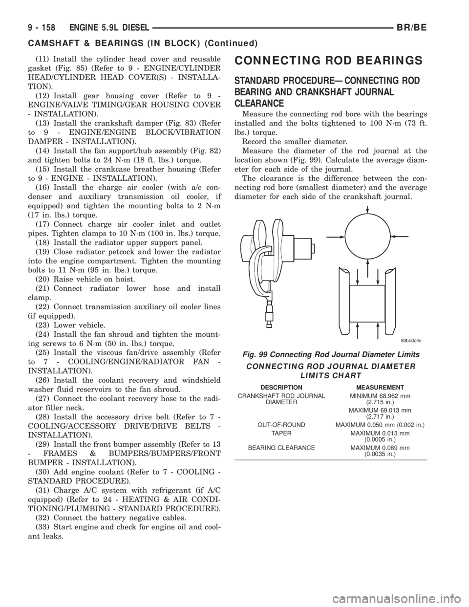
Measure the connecting rod bore with the bearings
installed and the bolts tightened to 100 N´m (73 ft.
lbs.) torque.
Record the smaller diameter.
Measure the diameter of the rod journal at the
location shown (Fig. 99). Calculate the average diam-
eter for each side of the journal.
The clearance is the difference between the con-
necting rod bore (smallest diameter) and the average
diameter for each side of the crankshaft journal.
Fig. 99 Connecting Rod Journal Diameter Limits
CONNECTING ROD JOURNAL DIAMETER
LIMITS CHART
DESCRIPTION MEASUREMENT
CRANKSHAFT ROD JOURNAL
DIAMETERMINIMUM 68.962 mm
(2.715 in.)
MAXIMUM 69.013 mm
(2.717 in.)
OUT-OF-ROUND MAXIMUM 0.050 mm (0.002 in.)
TAPER MAXIMUM 0.013 mm
(0.0005 in.)
BEARING CLEARANCE MAXIMUM 0.089 mm
(0.0035 in.)
9 - 158 ENGINE 5.9L DIESELBR/BE
CAMSHAFT & BEARINGS (IN BLOCK) (Continued)
Page 1256 of 2255
OIL PRESSURE SENSOR/
SWITCH
REMOVAL
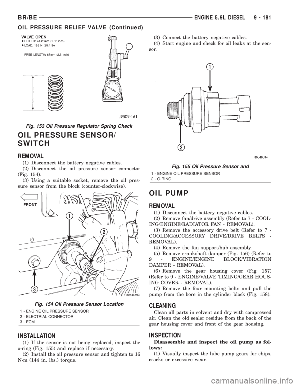
(1) Disconnect the battery negative cables.
(2) Disconnect the oil pressure sensor connector
(Fig. 154).
(3) Using a suitable socket, remove the oil pres-
sure sensor from the block (counter-clockwise).
INSTALLATION
(1) If the sensor is not being replaced, inspect the
o-ring (Fig. 155) and replace if necessary.
(2) Install the oil pressure sensor and tighten to 16
N´m (144 in. lbs.) torque.(3) Connect the battery negative cables.
(4) Start engine and check for oil leaks at the sen-
sor.
OIL PUMP
REMOVAL
(1) Disconnect the battery negative cables.
(2) Remove fan/drive assembly (Refer to 7 - COOL-
ING/ENGINE/RADIATOR FAN - REMOVAL).
(3) Remove the accessory drive belt (Refer to 7 -
COOLING/ACCESSORY DRIVE/DRIVE BELTS -
REMOVAL).
(4) Remove the fan support/hub assembly.
(5) Remove crankshaft damper (Fig. 156) (Refer to
9 - ENGINE/ENGINE BLOCK/VIBRATION
DAMPER - REMOVAL).
(6) Remove the gear housing cover (Fig. 157)
(Refer to 9 - ENGINE/VALVE TIMING/GEAR HOUS-
ING COVER - REMOVAL).
(7) Remove the four mounting bolts and pull the
pump from the bore in the cylinder block (Fig. 158).
CLEANING
Clean all parts in solvent and dry with compressed
air. Clean the old sealer residue from the back of the
gear housing cover and front of the gear housing.
INSPECTION
Disassemble and inspect the oil pump as fol-
lows:
(1) Visually inspect the lube pump gears for chips,
cracks or excessive wear.
Fig. 155 Oil Pressure Sensor and
1 - ENGINE OIL PRESSURE SENSOR
2 - O-RING
Fig. 153 Oil Pressure Regulator Spring Check
Fig. 154 Oil Pressure Sensor Location
1 - ENGINE OIL PRESSURE SENSOR
2 - ELECTRIAL CONNECTOR
3 - ECM
BR/BEENGINE 5.9L DIESEL 9 - 181
OIL PRESSURE RELIEF VALVE (Continued)
Page 1259 of 2255
(7) Apply a bead of MopartSilicone Rubber Adhe-
sive Sealant or equivalent to the gear housing cover
sealing surface.
(8) Install the gear housing cover (Refer to 9 -
ENGINE/VALVE TIMING/GEAR HOUSING COVER
- INSTALLATION).
(9) Install the vibration damper (Refer to 9 -
ENGINE/ENGINE BLOCK/VIBRATION DAMPER -
INSTALLATION).
(10) Install the fan support/hub assembly and
torque bolts to 24 N´m (18 ft. lbs.).
(11) Install the accessory drive belt (Refer to 7 -
COOLING/ACCESSORY DRIVE/DRIVE BELTS -
INSTALLATION).
(12) Install the cooling fan (Refer to 7 - COOLING/
ENGINE/RADIATOR FAN - INSTALLATION).
(13) Connect battery negative cables.
(14) Start engine and check for oil leaks.
INTAKE MANIFOLD
REMOVAL
(1) Disconnect the battery negative cables.
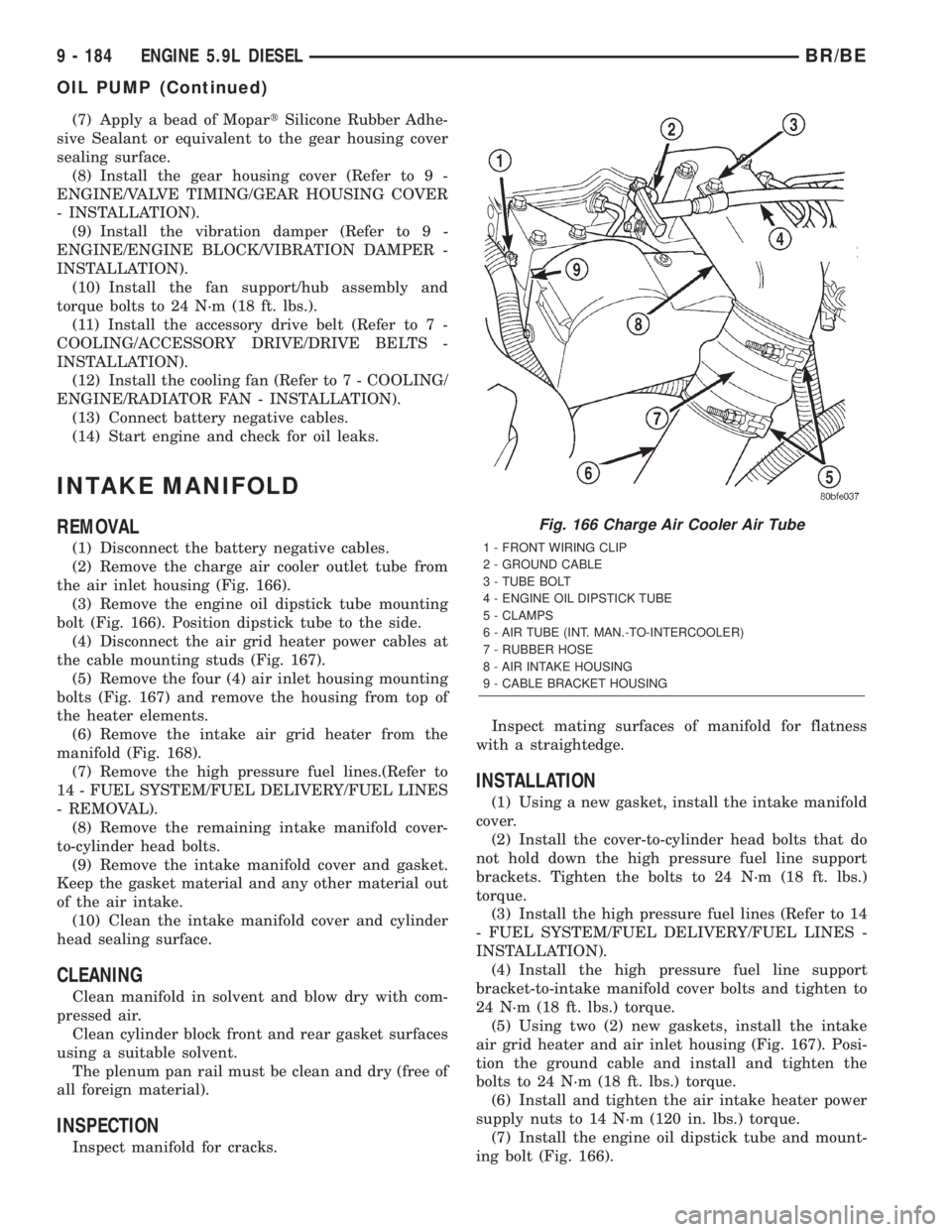
(2) Remove the charge air cooler outlet tube from
the air inlet housing (Fig. 166).
(3) Remove the engine oil dipstick tube mounting
bolt (Fig. 166). Position dipstick tube to the side.
(4) Disconnect the air grid heater power cables at
the cable mounting studs (Fig. 167).
(5) Remove the four (4) air inlet housing mounting
bolts (Fig. 167) and remove the housing from top of
the heater elements.
(6) Remove the intake air grid heater from the
manifold (Fig. 168).
(7) Remove the high pressure fuel lines.(Refer to
14 - FUEL SYSTEM/FUEL DELIVERY/FUEL LINES
- REMOVAL).
(8) Remove the remaining intake manifold cover-
to-cylinder head bolts.
(9) Remove the intake manifold cover and gasket.
Keep the gasket material and any other material out
of the air intake.
(10) Clean the intake manifold cover and cylinder
head sealing surface.
CLEANING
Clean manifold in solvent and blow dry with com-
pressed air.
Clean cylinder block front and rear gasket surfaces
using a suitable solvent.
The plenum pan rail must be clean and dry (free of
all foreign material).
INSPECTION
Inspect manifold for cracks.Inspect mating surfaces of manifold for flatness
with a straightedge.
INSTALLATION
(1) Using a new gasket, install the intake manifold
cover.
(2) Install the cover-to-cylinder head bolts that do
not hold down the high pressure fuel line support
brackets. Tighten the bolts to 24 N´m (18 ft. lbs.)
torque.
(3) Install the high pressure fuel lines (Refer to 14
- FUEL SYSTEM/FUEL DELIVERY/FUEL LINES -
INSTALLATION).
(4) Install the high pressure fuel line support
bracket-to-intake manifold cover bolts and tighten to
24 N´m (18 ft. lbs.) torque.
(5) Using two (2) new gaskets, install the intake
air grid heater and air inlet housing (Fig. 167). Posi-
tion the ground cable and install and tighten the
bolts to 24 N´m (18 ft. lbs.) torque.
(6) Install and tighten the air intake heater power
supply nuts to 14 N´m (120 in. lbs.) torque.
(7) Install the engine oil dipstick tube and mount-
ing bolt (Fig. 166).
Fig. 166 Charge Air Cooler Air Tube
1 - FRONT WIRING CLIP
2 - GROUND CABLE
3 - TUBE BOLT
4 - ENGINE OIL DIPSTICK TUBE
5 - CLAMPS
6 - AIR TUBE (INT. MAN.-TO-INTERCOOLER)
7 - RUBBER HOSE
8 - AIR INTAKE HOUSING
9 - CABLE BRACKET HOUSING
9 - 184 ENGINE 5.9L DIESELBR/BE
OIL PUMP (Continued)