2002 DODGE RAM clutch
[x] Cancel search: clutchPage 1767 of 2255
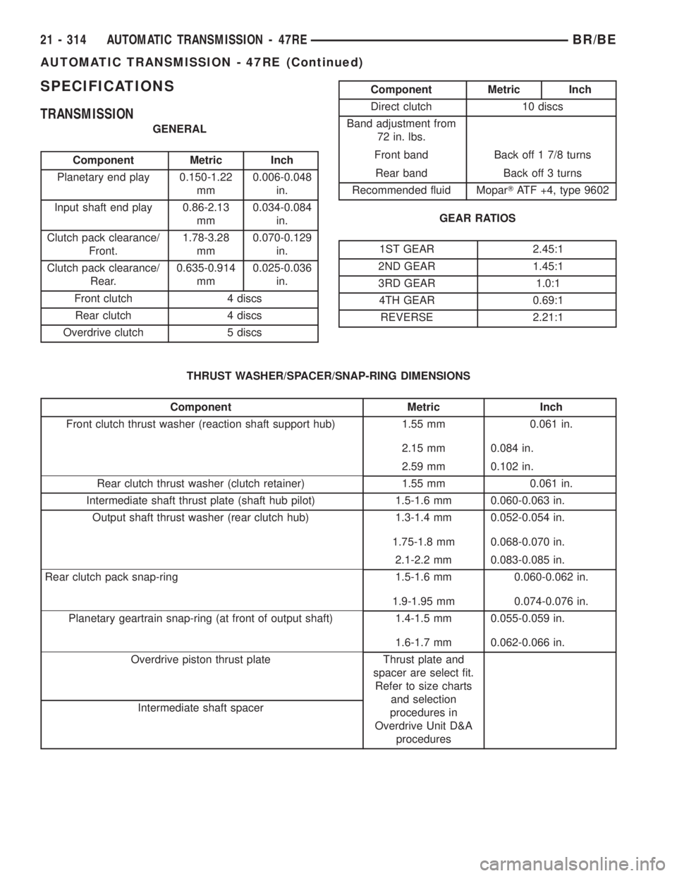
SPECIFICATIONS
TRANSMISSION
GENERAL
Component Metric Inch
Planetary end play 0.150-1.22
mm0.006-0.048
in.
Input shaft end play 0.86-2.13
mm0.034-0.084
in.
Clutch pack clearance/
Front.1.78-3.28
mm0.070-0.129
in.
Clutch pack clearance/
Rear.0.635-0.914
mm0.025-0.036
in.
Front clutch 4 discs
Rear clutch 4 discs
Overdrive clutch 5 discs
Component Metric Inch
Direct clutch 10 discs
Band adjustment from
72 in. lbs.
Front band Back off 1 7/8 turns
Rear band Back off 3 turns
Recommended fluid MoparTATF +4, type 9602
GEAR RATIOS
1ST GEAR 2.45:1
2ND GEAR 1.45:1
3RD GEAR 1.0:1
4TH GEAR 0.69:1
REVERSE 2.21:1
THRUST WASHER/SPACER/SNAP-RING DIMENSIONS
Component Metric Inch
Front clutch thrust washer (reaction shaft support hub) 1.55 mm 0.061 in.
2.15 mm 0.084 in.
2.59 mm 0.102 in.
Rear clutch thrust washer (clutch retainer) 1.55 mm 0.061 in.
Intermediate shaft thrust plate (shaft hub pilot) 1.5-1.6 mm 0.060-0.063 in.
Output shaft thrust washer (rear clutch hub) 1.3-1.4 mm 0.052-0.054 in.
1.75-1.8 mm 0.068-0.070 in.
2.1-2.2 mm 0.083-0.085 in.
Rear clutch pack snap-ring 1.5-1.6 mm 0.060-0.062 in.
1.9-1.95 mm 0.074-0.076 in.
Planetary geartrain snap-ring (at front of output shaft) 1.4-1.5 mm 0.055-0.059 in.
1.6-1.7 mm 0.062-0.066 in.
Overdrive piston thrust plate Thrust plate and
spacer are select fit.
Refer to size charts
and selection
procedures in
Overdrive Unit D&A
procedures Intermediate shaft spacer
21 - 314 AUTOMATIC TRANSMISSION - 47REBR/BE
AUTOMATIC TRANSMISSION - 47RE (Continued)
Page 1768 of 2255
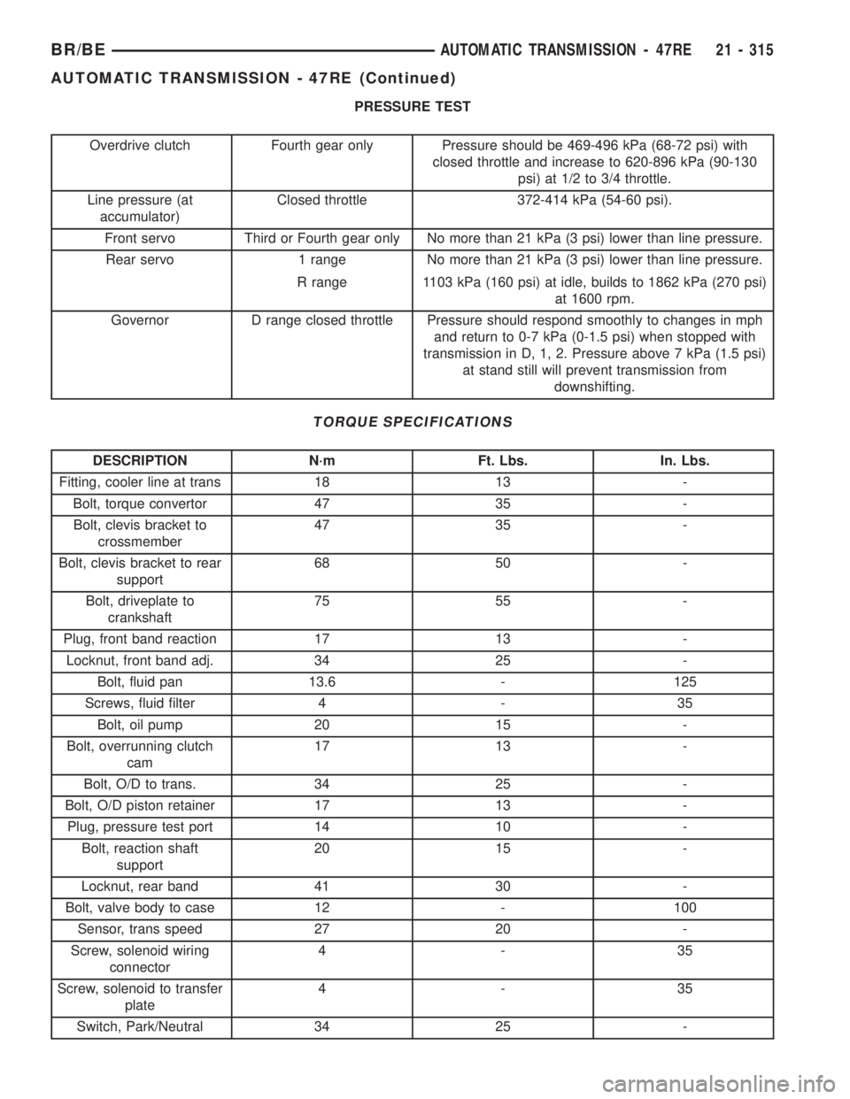
PRESSURE TEST
Overdrive clutch Fourth gear only Pressure should be 469-496 kPa (68-72 psi) with
closed throttle and increase to 620-896 kPa (90-130
psi) at 1/2 to 3/4 throttle.
Line pressure (at
accumulator)Closed throttle 372-414 kPa (54-60 psi).
Front servo Third or Fourth gear only No more than 21 kPa (3 psi) lower than line pressure.
Rear servo 1 range No more than 21 kPa (3 psi) lower than line pressure.
R range 1103 kPa (160 psi) at idle, builds to 1862 kPa (270 psi)
at 1600 rpm.
Governor D range closed throttle Pressure should respond smoothly to changes in mph
and return to 0-7 kPa (0-1.5 psi) when stopped with
transmission in D, 1, 2. Pressure above 7 kPa (1.5 psi)
at stand still will prevent transmission from
downshifting.
TORQUE SPECIFICATIONS
DESCRIPTION N´m Ft. Lbs. In. Lbs.
Fitting, cooler line at trans 18 13 -
Bolt, torque convertor 47 35 -
Bolt, clevis bracket to
crossmember47 35 -
Bolt, clevis bracket to rear
support68 50 -
Bolt, driveplate to
crankshaft75 55 -
Plug, front band reaction 17 13 -
Locknut, front band adj. 34 25 -
Bolt, fluid pan 13.6 - 125
Screws, fluid filter 4 - 35
Bolt, oil pump 20 15 -
Bolt, overrunning clutch
cam17 13 -
Bolt, O/D to trans. 34 25 -
Bolt, O/D piston retainer 17 13 -
Plug, pressure test port 14 10 -
Bolt, reaction shaft
support20 15 -
Locknut, rear band 41 30 -
Bolt, valve body to case 12 - 100
Sensor, trans speed 27 20 -
Screw, solenoid wiring
connector4-35
Screw, solenoid to transfer
plate4-35
Switch, Park/Neutral 34 25 -
BR/BEAUTOMATIC TRANSMISSION - 47RE 21 - 315
AUTOMATIC TRANSMISSION - 47RE (Continued)
Page 1771 of 2255
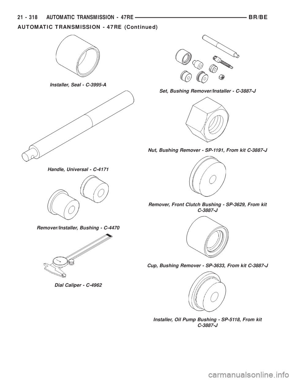
Installer, Seal - C-3995-A
Handle, Universal - C-4171
Remover/Installer, Bushing - C-4470
Dial Caliper - C-4962
Set, Bushing Remover/Installer - C-3887-J
Nut, Bushing Remover - SP-1191, From kit C-3887-J
Remover, Front Clutch Bushing - SP-3629, From kit
C-3887-J
Cup, Bushing Remover - SP-3633, From kit C-3887-J
Installer, Oil Pump Bushing - SP-5118, From kit
C-3887-J
21 - 318 AUTOMATIC TRANSMISSION - 47REBR/BE
AUTOMATIC TRANSMISSION - 47RE (Continued)
Page 1772 of 2255
ACCUMULATOR
DESCRIPTION
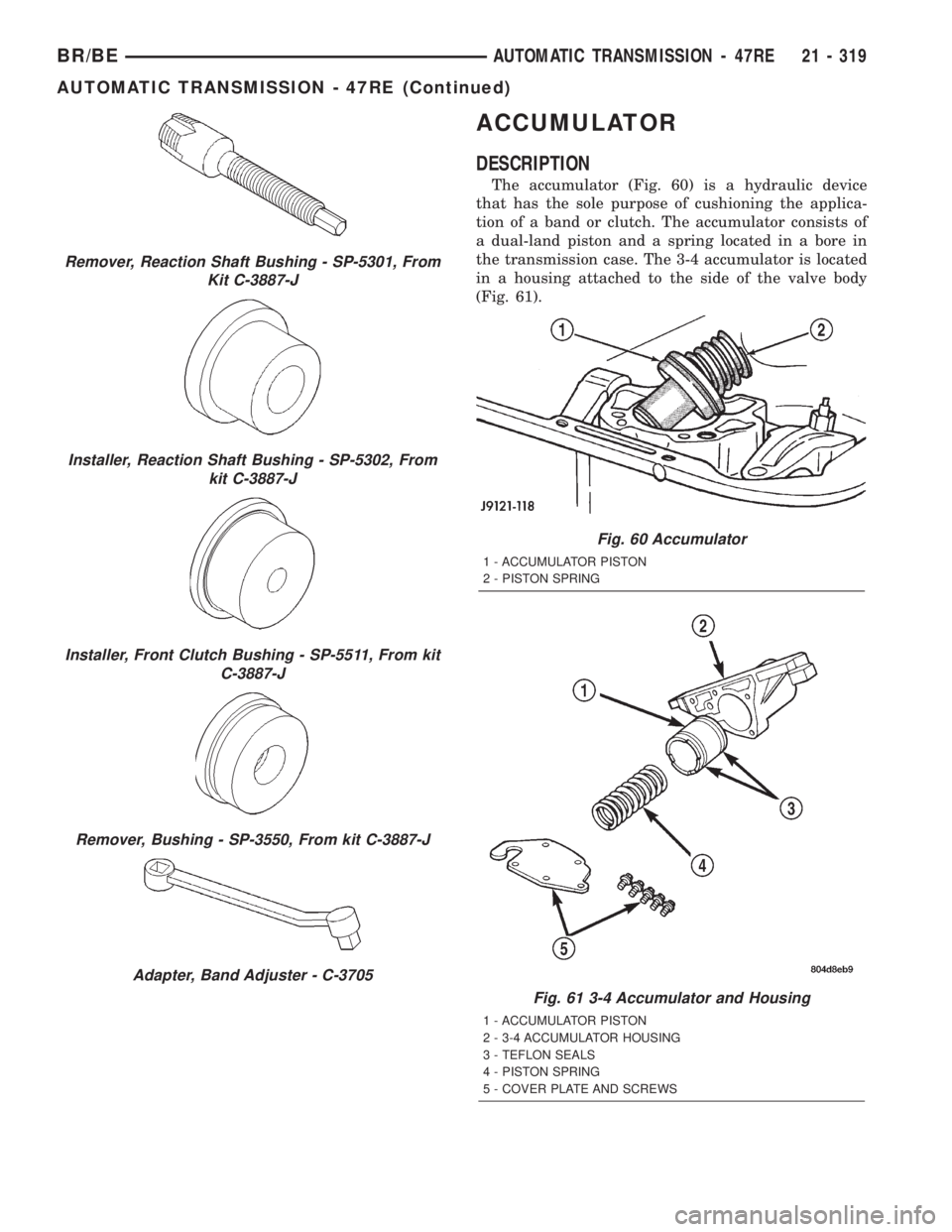
The accumulator (Fig. 60) is a hydraulic device
that has the sole purpose of cushioning the applica-
tion of a band or clutch. The accumulator consists of
a dual-land piston and a spring located in a bore in
the transmission case. The 3-4 accumulator is located
in a housing attached to the side of the valve body
(Fig. 61).
Remover, Reaction Shaft Bushing - SP-5301, From
Kit C-3887-J
Installer, Reaction Shaft Bushing - SP-5302, From
kit C-3887-J
Installer, Front Clutch Bushing - SP-5511, From kit
C-3887-J
Remover, Bushing - SP-3550, From kit C-3887-J
Adapter, Band Adjuster - C-3705
Fig. 60 Accumulator
1 - ACCUMULATOR PISTON
2 - PISTON SPRING
Fig. 61 3-4 Accumulator and Housing
1 - ACCUMULATOR PISTON
2 - 3-4 ACCUMULATOR HOUSING
3 - TEFLON SEALS
4 - PISTON SPRING
5 - COVER PLATE AND SCREWS
BR/BEAUTOMATIC TRANSMISSION - 47RE 21 - 319
AUTOMATIC TRANSMISSION - 47RE (Continued)
Page 1773 of 2255
OPERATION
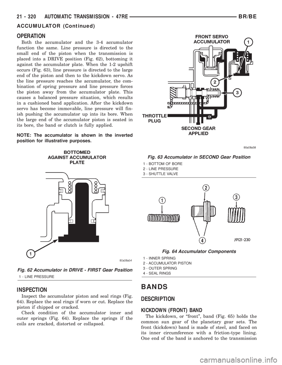
Both the accumulator and the 3-4 accumulator
function the same. Line pressure is directed to the
small end of the piston when the transmission is
placed into a DRIVE position (Fig. 62), bottoming it
against the accumulator plate. When the 1-2 upshift
occurs (Fig. 63), line pressure is directed to the large
end of the piston and then to the kickdown servo. As
the line pressure reaches the accumulator, the com-
bination of spring pressure and line pressure forces
the piston away from the accumulator plate. This
causes a balanced pressure situation, which results
in a cushioned band application. After the kickdown
servo has become immovable, line pressure will fin-
ish pushing the accumulator up into its bore. When
the large end of the accumulator piston is seated in
its bore, the band or clutch is fully applied.
NOTE: The accumulator is shown in the inverted
position for illustrative purposes.
INSPECTION
Inspect the accumulator piston and seal rings (Fig.
64). Replace the seal rings if worn or cut. Replace the
piston if chipped or cracked.
Check condition of the accumulator inner and
outer springs (Fig. 64). Replace the springs if the
coils are cracked, distorted or collapsed.
BANDS
DESCRIPTION
KICKDOWN (FRONT) BAND
The kickdown, or ªfrontº, band (Fig. 65) holds the
common sun gear of the planetary gear sets. The
front (kickdown) band is made of steel, and faced on
its inner circumference with a friction-type lining.
One end of the band is anchored to the transmission
Fig. 62 Accumulator in DRIVE - FIRST Gear Position
1 - LINE PRESSURE
Fig. 63 Accumulator in SECOND Gear Position
1 - BOTTOM OF BORE
2 - LINE PRESSURE
3 - SHUTTLE VALVE
Fig. 64 Accumulator Components
1 - INNER SPRING
2 - ACCUMULATOR PISTON
3 - OUTER SPRING
4 - SEAL RINGS
21 - 320 AUTOMATIC TRANSMISSION - 47REBR/BE
ACCUMULATOR (Continued)
Page 1774 of 2255
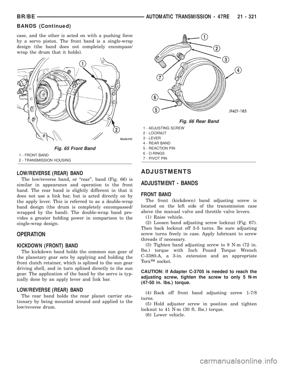
case, and the other is acted on with a pushing force
by a servo piston. The front band is a single-wrap
design (the band does not completely encompass/
wrap the drum that it holds).
LOW/REVERSE (REAR) BAND
The low/reverse band, or ªrearº, band (Fig. 66) is
similar in appearance and operation to the front
band. The rear band is slightly different in that it
does not use a link bar, but is acted directly on by
the apply lever. This is referred to as a double-wrap
band design (the drum is completely encompassed/
wrapped by the band). The double-wrap band pro-
vides a greater holding power in comparison to the
single-wrap design.
OPERATION
KICKDOWN (FRONT) BAND
The kickdown band holds the common sun gear of
the planetary gear sets by applying and holding the
front clutch retainer, which is splined to the sun gear
driving shell, and in turn splined directly to the sun
gear. The application of the band by the servo is typ-
ically done by an apply lever and link bar.
LOW/REVERSE (REAR) BAND
The rear band holds the rear planet carrier sta-
tionary by being mounted around and applied to the
low/reverse drum.
ADJUSTMENTS
ADJUSTMENT - BANDS
FRONT BAND
The front (kickdown) band adjusting screw is
located on the left side of the transmission case
above the manual valve and throttle valve levers.
(1) Raise vehicle.
(2) Loosen band adjusting screw locknut (Fig. 67).
Then back locknut off 3-5 turns. Be sure adjusting
screw turns freely in case. Apply lubricant to screw
threads if necessary.
(3) Tighten band adjusting screw to 8 N´m (72 in.
lbs.) torque with Inch Pound Torque Wrench
C-3380-A, a 3-in. extension and an appropriate
TorxŸ socket.
CAUTION: If Adapter C-3705 is needed to reach the
adjusting screw, tighten the screw to only 5 N´m
(47-50 in. lbs.) torque.
(4) Back off front band adjusting screw 1-7/8
turns.
(5) Hold adjuster screw in position and tighten
locknut to 41 N´m (30 ft. lbs.) torque.
(6) Lower vehicle.
Fig. 65 Front Band
1 - FRONT BAND
2 - TRANSMISSION HOUSING
Fig. 66 Rear Band
1 - ADJUSTING SCREW
2 - LOCKNUT
3 - LEVER
4 - REAR BAND
5 - REACTION PIN
6 - O-RINGS
7 - PIVOT PIN
BR/BEAUTOMATIC TRANSMISSION - 47RE 21 - 321
BANDS (Continued)
Page 1780 of 2255
INSTALLATION
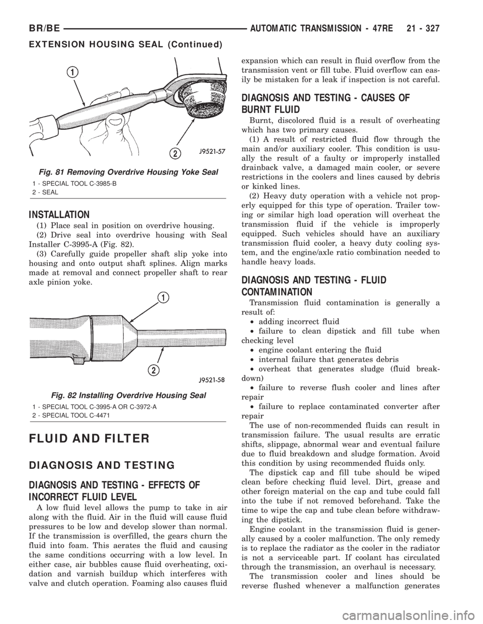
(1) Place seal in position on overdrive housing.
(2) Drive seal into overdrive housing with Seal
Installer C-3995-A (Fig. 82).
(3) Carefully guide propeller shaft slip yoke into
housing and onto output shaft splines. Align marks
made at removal and connect propeller shaft to rear
axle pinion yoke.
FLUID AND FILTER
DIAGNOSIS AND TESTING
DIAGNOSIS AND TESTING - EFFECTS OF
INCORRECT FLUID LEVEL
A low fluid level allows the pump to take in air
along with the fluid. Air in the fluid will cause fluid
pressures to be low and develop slower than normal.
If the transmission is overfilled, the gears churn the
fluid into foam. This aerates the fluid and causing
the same conditions occurring with a low level. In
either case, air bubbles cause fluid overheating, oxi-
dation and varnish buildup which interferes with
valve and clutch operation. Foaming also causes fluidexpansion which can result in fluid overflow from the
transmission vent or fill tube. Fluid overflow can eas-
ily be mistaken for a leak if inspection is not careful.
DIAGNOSIS AND TESTING - CAUSES OF
BURNT FLUID
Burnt, discolored fluid is a result of overheating
which has two primary causes.
(1) A result of restricted fluid flow through the
main and/or auxiliary cooler. This condition is usu-
ally the result of a faulty or improperly installed
drainback valve, a damaged main cooler, or severe
restrictions in the coolers and lines caused by debris
or kinked lines.
(2) Heavy duty operation with a vehicle not prop-
erly equipped for this type of operation. Trailer tow-
ing or similar high load operation will overheat the
transmission fluid if the vehicle is improperly
equipped. Such vehicles should have an auxiliary
transmission fluid cooler, a heavy duty cooling sys-
tem, and the engine/axle ratio combination needed to
handle heavy loads.
DIAGNOSIS AND TESTING - FLUID
CONTAMINATION
Transmission fluid contamination is generally a
result of:
²adding incorrect fluid
²failure to clean dipstick and fill tube when
checking level
²engine coolant entering the fluid
²internal failure that generates debris
²overheat that generates sludge (fluid break-
down)
²failure to reverse flush cooler and lines after
repair
²failure to replace contaminated converter after
repair
The use of non-recommended fluids can result in
transmission failure. The usual results are erratic
shifts, slippage, abnormal wear and eventual failure
due to fluid breakdown and sludge formation. Avoid
this condition by using recommended fluids only.
The dipstick cap and fill tube should be wiped
clean before checking fluid level. Dirt, grease and
other foreign material on the cap and tube could fall
into the tube if not removed beforehand. Take the
time to wipe the cap and tube clean before withdraw-
ing the dipstick.
Engine coolant in the transmission fluid is gener-
ally caused by a cooler malfunction. The only remedy
is to replace the radiator as the cooler in the radiator
is not a serviceable part. If coolant has circulated
through the transmission, an overhaul is necessary.
The transmission cooler and lines should be
reverse flushed whenever a malfunction generates
Fig. 81 Removing Overdrive Housing Yoke Seal
1 - SPECIAL TOOL C-3985-B
2 - SEAL
Fig. 82 Installing Overdrive Housing Seal
1 - SPECIAL TOOL C-3995-A OR C-3972-A
2 - SPECIAL TOOL C-4471
BR/BEAUTOMATIC TRANSMISSION - 47RE 21 - 327
EXTENSION HOUSING SEAL (Continued)
Page 1781 of 2255
sludge and/or debris. The torque converter should
also be replaced at the same time.
Failure to flush the cooler and lines will result in
recontamination. Flushing applies to auxiliary cool-
ers as well. The torque converter should also be
replaced whenever a failure generates sludge and
debris. This is necessary because normal converter
flushing procedures will not remove all contami-
nants.
STANDARD PROCEDURE
STANDARD PROCEDURE - FLUID LEVEL
CHECK
Low fluid level can cause a variety of conditions
because it allows the pump to take in air along with
the fluid. As in any hydraulic system, air bubbles
make the fluid spongy, therefore, pressures will be
low and build up slowly.
Improper filling can also raise the fluid level too
high. When the transmssion has too much fluid, the
geartrain churns up foam and cause the same condi-
tions which occur with a low fluid level.
In either case, air bubbles can cause overheating
and/or fluid oxidation, and varnishing. This can
interfere with normal valve, clutch, and accumulator
operation. Foaming can also result in fluid escaping
from the transmission vent where it may be mis-
taken for a leak.
Along with fluid level, it is important to check the
condition of the fluid. When the fluid smells burned,
and is contaminated with metal or friction material
particles, a complete transmission recondition is
needed. Be sure to examine the fluid on the dipstick
closely. If there is any doubt about its condition,
drain out a sample for a double check.
After the fluid has been checked, seat the dipstick
fully to seal out water and dirt.
The transmission has a dipstick to check oil level.
It is located on the right side of the engine. Be sure
to wipe all dirt from dipstick handle before removing.
Fluid level is checked with the engine running at
curb idle speed, the transmission in NEUTRAL and
the transmission fluid at normal operating tempera-
ture.The engine should be running at idle
speed for at least one minute, with the vehicle
on level ground.
The transmission fluid level can be checked two
ways.
PROCEDURE ONE
(1) Transmission fluid must be at normal operat-
ing temperature for accurate fluid level check. Drive
vehicle if necessary to bring fluid temperature up to
normal hot operating temperature of 82ÉC (180ÉF).(2) Position vehicle on level surface.
(3) Start and run engine at curb idle speed.
(4) Apply parking brakes.
(5) Shift transmission momentarily into all gear
ranges. Then shift transmission back to NEUTRAL.
(6) Clean top of filler tube and dipstick to keep
dirt from entering tube.
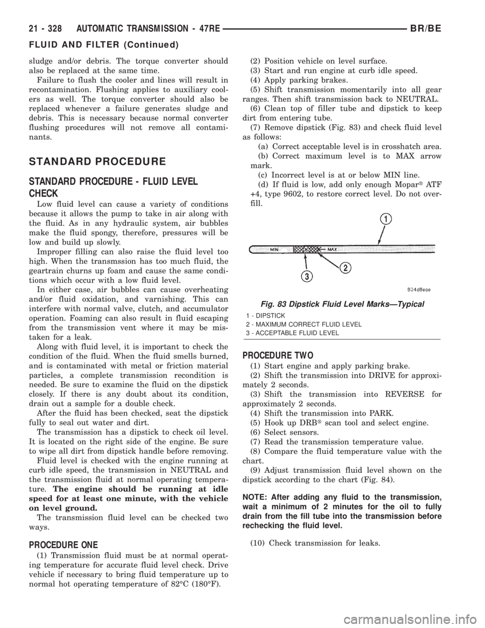
(7) Remove dipstick (Fig. 83) and check fluid level
as follows:
(a) Correct acceptable level is in crosshatch area.
(b) Correct maximum level is to MAX arrow
mark.
(c) Incorrect level is at or below MIN line.
(d) If fluid is low, add only enough MopartAT F
+4, type 9602, to restore correct level. Do not over-
fill.
PROCEDURE TWO
(1) Start engine and apply parking brake.
(2) Shift the transmission into DRIVE for approxi-
mately 2 seconds.
(3) Shift the transmission into REVERSE for
approximately 2 seconds.
(4) Shift the transmission into PARK.
(5) Hook up DRBtscan tool and select engine.
(6) Select sensors.
(7) Read the transmission temperature value.
(8) Compare the fluid temperature value with the
chart.
(9) Adjust transmission fluid level shown on the
dipstick according to the chart (Fig. 84).
NOTE: After adding any fluid to the transmission,
wait a minimum of 2 minutes for the oil to fully
drain from the fill tube into the transmission before
rechecking the fluid level.
(10) Check transmission for leaks.
Fig. 83 Dipstick Fluid Level MarksÐTypical
1 - DIPSTICK
2 - MAXIMUM CORRECT FLUID LEVEL
3 - ACCEPTABLE FLUID LEVEL
21 - 328 AUTOMATIC TRANSMISSION - 47REBR/BE
FLUID AND FILTER (Continued)