Page 1749 of 2255

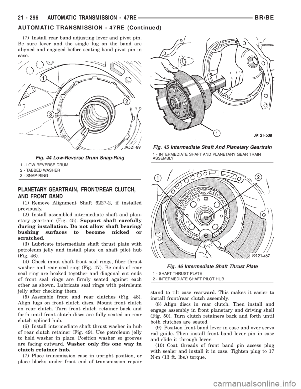
(7) Install rear band adjusting lever and pivot pin.
Be sure lever and the single lug on the band are
aligned and engaged before seating band pivot pin in
case.
PLANETARY GEARTRAIN, FRONT/REAR CLUTCH,
AND FRONT BAND
(1) Remove Alignment Shaft 6227-2, if installed
previously.
(2) Install assembled intermediate shaft and plan-
etary geartrain (Fig. 45).Support shaft carefully
during installation. Do not allow shaft bearing/
bushing surfaces to become nicked or
scratched.
(3) Lubricate intermediate shaft thrust plate with
petroleum jelly and install plate on shaft pilot hub
(Fig. 46).
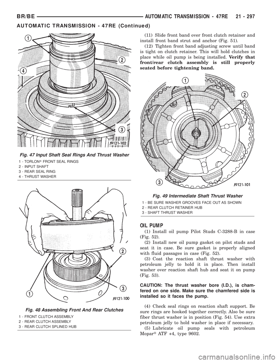
(4) Check input shaft front seal rings, fiber thrust
washer and rear seal ring (Fig. 47). Be ends of rear
seal ring are hooked together and diagonal cut ends
of front seal rings are firmly seated against each
other as shown. Lubricate seal rings with petroleum
jelly after checking them.
(5) Assemble front and rear clutches (Fig. 48).
Align lugs on front clutch discs. Mount front clutch
on rear clutch. Turn front clutch retainer back and
forth until front clutch discs are fully seated on rear
clutch splined hub.
(6) Install intermediate shaft thrust washer in hub
of rear clutch retainer (Fig. 49). Use petroleum jelly
to hold washer in place. Position washer so grooves
are facing outward.Washer only fits one way in
clutch retainer hub.
(7) Place transmission case in upright position, or
place blocks under front end of transmission repairstand to tilt case rearward. This makes it easier to
install front/rear clutch assembly.
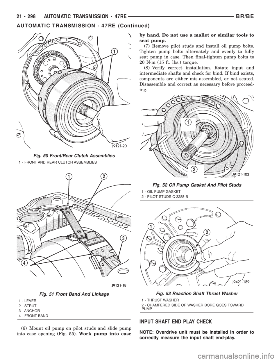
(8) Align discs in rear clutch. Then install and
engage assembly in front planetary and driving shell
(Fig. 50). Turn clutch retainers back and forth until
both clutches are seated.
(9) Position front band lever in case and over servo
rod guide. Then install front band lever pin in case
and slide it through lever.
(10) Coat threads of front band pin access plug
with sealer and install it in case. Tighten plug to 17
N´m (13 ft. lbs.) torque.
Fig. 44 Low-Reverse Drum Snap-Ring
1 - LOW-REVERSE DRUM
2 - TABBED WASHER
3 - SNAP-RING
Fig. 45 Intermediate Shaft And Planetary Geartrain
1 - INTERMEDIATE SHAFT AND PLANETARY GEAR TRAIN
ASSEMBLY
Fig. 46 Intermediate Shaft Thrust Plate
1 - SHAFT THRUST PLATE
2 - INTERMEDIATE SHAFT PILOT HUB
21 - 296 AUTOMATIC TRANSMISSION - 47REBR/BE
AUTOMATIC TRANSMISSION - 47RE (Continued)
Page 1750 of 2255

(11) Slide front band over front clutch retainer and
install front band strut and anchor (Fig. 51).
(12) Tighten front band adjusting screw until band
is tight on clutch retainer. This will hold clutches in
place while oil pump is being installed.Verify that
front/rear clutch assembly is still properly
seated before tightening band.
OIL PUMP
(1) Install oil pump Pilot Studs C-3288-B in case
(Fig. 52).
(2) Install new oil pump gasket on pilot studs and
seat it in case. Be sure gasket is properly aligned
with fluid passages in case (Fig. 52).
(3) Coat the reaction shaft thrust washer with
petroleum jelly to hold it in place. Then install
washer over reaction shaft hub and seat it on pump
(Fig. 53).
CAUTION: The thrust washer bore (I.D.), is cham-
fered on one side. Make sure the chamfered side is
installed so it faces the pump.
(4) Check seal rings on reaction shaft support. Be
sure rings are hooked together correctly. Also be sure
fiber thrust washer is in position (Fig. 54). Use extra
petroleum jelly to hold washer in place if necessary.
(5) Lubricate oil pump seals with petroleum
MopartATF +4, type 9602.
Fig. 47 Input Shaft Seal Rings And Thrust Washer
1 - TORLONTFRONT SEAL RINGS
2 - INPUT SHAFT
3 - REAR SEAL RING
4 - THRUST WASHER
Fig. 48 Assembling Front And Rear Clutches
1 - FRONT CLUTCH ASSEMBLY
2 - REAR CLUTCH ASSEMBLY
3 - REAR CLUTCH SPLINED HUB
Fig. 49 Intermediate Shaft Thrust Washer
1 - BE SURE WASHER GROOVES FACE OUT AS SHOWN
2 - REAR CLUTCH RETAINER HUB
3 - SHAFT THRUST WASHER
BR/BEAUTOMATIC TRANSMISSION - 47RE 21 - 297
AUTOMATIC TRANSMISSION - 47RE (Continued)
Page 1751 of 2255

(6) Mount oil pump on pilot studs and slide pump
into case opening (Fig. 55).Work pump into caseby hand. Do not use a mallet or similar tools to
seat pump.
(7) Remove pilot studs and install oil pump bolts.
Tighten pump bolts alternately and evenly to fully
seat pump in case. Then final-tighten pump bolts to
20 N´m (15 ft. lbs.) torque.
(8) Verify correct installation. Rotate input and
intermediate shafts and check for bind. If bind exists,
components are either mis-assembled, or not seated.
Disassemble and correct as necessary before proceed-
ing.
INPUT SHAFT END PLAY CHECK
NOTE: Overdrive unit must be installed in order to
correctly measure the input shaft end-play.
Fig. 50 Front/Rear Clutch Assemblies
1 - FRONT AND REAR CLUTCH ASSEMBLIES
Fig. 51 Front Band And Linkage
1 - LEVER
2 - STRUT
3 - ANCHOR
4 - FRONT BAND
Fig. 52 Oil Pump Gasket And Pilot Studs
1 - OIL PUMP GASKET
2 - PILOT STUDS C-3288-B
Fig. 53 Reaction Shaft Thrust Washer
1 - THRUST WASHER
2 - CHAMFERED SIDE OF WASHER BORE GOES TOWARD
PUMP
21 - 298 AUTOMATIC TRANSMISSION - 47REBR/BE
AUTOMATIC TRANSMISSION - 47RE (Continued)
Page 1754 of 2255

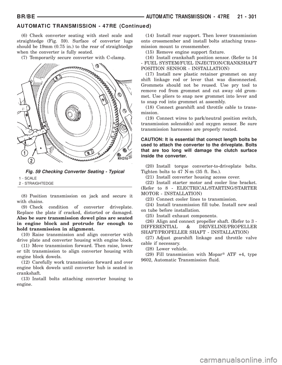
(6) Check converter seating with steel scale and
straightedge (Fig. 59). Surface of converter lugs
should be 19mm (0.75 in.) to the rear of straightedge
when the converter is fully seated.
(7) Temporarily secure converter with C-clamp.
(8) Position transmission on jack and secure it
with chains.
(9) Check condition of converter driveplate.
Replace the plate if cracked, distorted or damaged.
Also be sure transmission dowel pins are seated
in engine block and protrude far enough to
hold transmission in alignment.
(10) Raise transmission and align converter with
drive plate and converter housing with engine block.
(11) Move transmission forward. Then raise, lower
or tilt transmission to align converter housing with
engine block dowels.
(12) Carefully work transmission forward and over
engine block dowels until converter hub is seated in
crankshaft.
(13) Install bolts attaching converter housing to
engine.(14) Install rear support. Then lower transmission
onto crossmember and install bolts attaching trans-
mission mount to crossmember.
(15) Remove engine support fixture.
(16) Install crankshaft position sensor. (Refer to 14
- FUEL SYSTEM/FUEL INJECTION/CRANKSHAFT
POSITION SENSOR - INSTALLATION)
(17) Install new plastic retainer grommet on any
shift linkage rod or lever that was disconnected.
Grommets should not be reused. Use pry tool to
remove rod from grommet and cut away old grom-
met. Use pliers to snap new grommet into lever and
to snap rod into grommet at assembly.
(18) Connect gearshift and throttle cable to trans-
mission.
(19) Connect wires to park/neutral position switch,
transmission solenoid(s) and oxygen sensor. Be sure
transmission harnesses are properly routed.
CAUTION: It is essential that correct length bolts be
used to attach the converter to the driveplate. Bolts
that are too long will damage the clutch surface
inside the converter.
(20) Install torque converter-to-driveplate bolts.
Tighten bolts to 47 N´m (35 ft. lbs.).
(21) Install converter housing access cover.
(22) Install starter motor and cooler line bracket.
(Refer to 8 - ELECTRICAL/STARTING/STARTER
MOTOR - INSTALLATION)
(23) Connect cooler lines to transmission.
(24) Install transmission fill tube. Install new seal
on tube before installation.
(25) Install exhaust components.
(26) Align and connect propeller shaft. (Refer to 3 -
DIFFERENTIAL & DRIVELINE/PROPELLER
SHAFT/PROPELLER SHAFT - INSTALLATION)
(27) Adjust gearshift linkage and throttle valve
cable if necessary.
(28) Lower vehicle.
(29) Fill transmission with MopartATF +4, type
9602, Automatic Transmission fluid.
Fig. 59 Checking Converter Seating - Typical
1 - SCALE
2 - STRAIGHTEDGE
BR/BEAUTOMATIC TRANSMISSION - 47RE 21 - 301
AUTOMATIC TRANSMISSION - 47RE (Continued)
Page 1760 of 2255
HYDRAULIC FLOW IN DRIVE THIRD GEAR (CONVERTER CLUTCH NOT APPLIED)
BR/BEAUTOMATIC TRANSMISSION - 47RE 21 - 307
AUTOMATIC TRANSMISSION - 47RE (Continued)
Page 1761 of 2255
HYDRAULIC FLOW IN DRIVE THIRD GEAR (CONVERTER CLUTCH APPLIED)
21 - 308 AUTOMATIC TRANSMISSION - 47REBR/BE
AUTOMATIC TRANSMISSION - 47RE (Continued)
Page 1762 of 2255
HYDRAULIC FLOW IN DRIVE FOURTH GEAR (CONVERTER CLUTCH NOT APPLIED)
BR/BEAUTOMATIC TRANSMISSION - 47RE 21 - 309
AUTOMATIC TRANSMISSION - 47RE (Continued)
Page 1763 of 2255
HYDRAULIC FLOW IN DRIVE FOURTH GEAR (CONVERTER CLUTCH APPLIED)
21 - 310 AUTOMATIC TRANSMISSION - 47REBR/BE
AUTOMATIC TRANSMISSION - 47RE (Continued)