2002 DODGE RAM wheel
[x] Cancel search: wheelPage 1061 of 2255
tribution points for the electrical current required to
operate all of the many standard and optional facto-
ry-installed electrical and electronic powertrain,
chassis, safety, security, comfort and convenience sys-
tems. At the same time, the power distribution sys-
tem was designed to provide ready access to these
electrical distribution points for the vehicle techni-
cian to use when conducting diagnosis and repair of
faulty circuits. The power distribution system can
also prove useful for the sourcing of additional elec-
trical circuits that may be required to provide the
electrical current needed to operate many accessories
that the vehicle owner may choose to have installed
in the aftermarket.
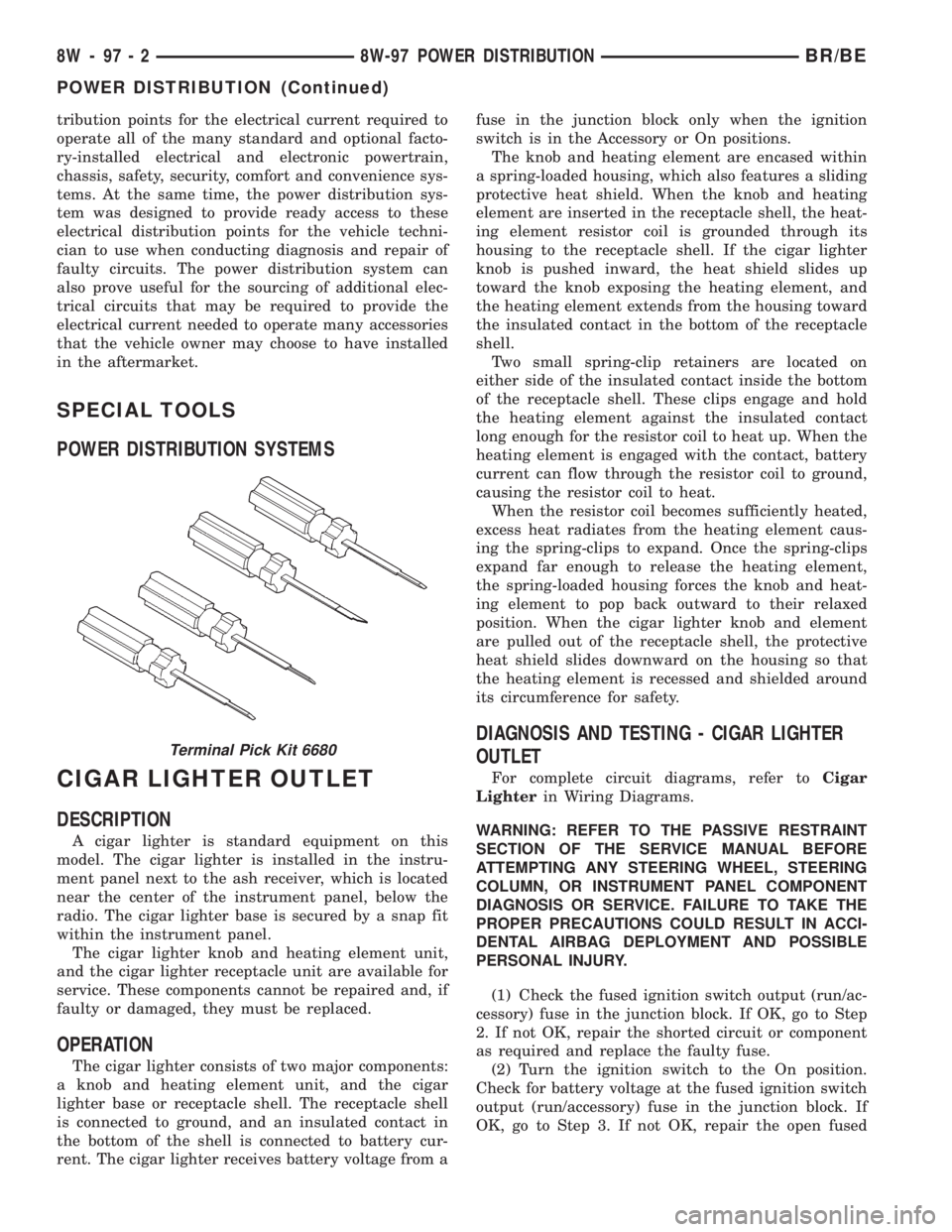
SPECIAL TOOLS
POWER DISTRIBUTION SYSTEMS
CIGAR LIGHTER OUTLET
DESCRIPTION
A cigar lighter is standard equipment on this
model. The cigar lighter is installed in the instru-
ment panel next to the ash receiver, which is located
near the center of the instrument panel, below the
radio. The cigar lighter base is secured by a snap fit
within the instrument panel.
The cigar lighter knob and heating element unit,
and the cigar lighter receptacle unit are available for
service. These components cannot be repaired and, if
faulty or damaged, they must be replaced.
OPERATION
The cigar lighter consists of two major components:
a knob and heating element unit, and the cigar
lighter base or receptacle shell. The receptacle shell
is connected to ground, and an insulated contact in
the bottom of the shell is connected to battery cur-
rent. The cigar lighter receives battery voltage from afuse in the junction block only when the ignition
switch is in the Accessory or On positions.
The knob and heating element are encased within
a spring-loaded housing, which also features a sliding
protective heat shield. When the knob and heating
element are inserted in the receptacle shell, the heat-
ing element resistor coil is grounded through its
housing to the receptacle shell. If the cigar lighter
knob is pushed inward, the heat shield slides up
toward the knob exposing the heating element, and
the heating element extends from the housing toward
the insulated contact in the bottom of the receptacle
shell.
Two small spring-clip retainers are located on
either side of the insulated contact inside the bottom
of the receptacle shell. These clips engage and hold
the heating element against the insulated contact
long enough for the resistor coil to heat up. When the
heating element is engaged with the contact, battery
current can flow through the resistor coil to ground,
causing the resistor coil to heat.
When the resistor coil becomes sufficiently heated,
excess heat radiates from the heating element caus-
ing the spring-clips to expand. Once the spring-clips
expand far enough to release the heating element,
the spring-loaded housing forces the knob and heat-
ing element to pop back outward to their relaxed
position. When the cigar lighter knob and element
are pulled out of the receptacle shell, the protective
heat shield slides downward on the housing so that
the heating element is recessed and shielded around
its circumference for safety.
DIAGNOSIS AND TESTING - CIGAR LIGHTER
OUTLET
For complete circuit diagrams, refer toCigar
Lighterin Wiring Diagrams.
WARNING: REFER TO THE PASSIVE RESTRAINT
SECTION OF THE SERVICE MANUAL BEFORE
ATTEMPTING ANY STEERING WHEEL, STEERING
COLUMN, OR INSTRUMENT PANEL COMPONENT
DIAGNOSIS OR SERVICE. FAILURE TO TAKE THE
PROPER PRECAUTIONS COULD RESULT IN ACCI-
DENTAL AIRBAG DEPLOYMENT AND POSSIBLE
PERSONAL INJURY.
(1) Check the fused ignition switch output (run/ac-
cessory) fuse in the junction block. If OK, go to Step
2. If not OK, repair the shorted circuit or component
as required and replace the faulty fuse.
(2) Turn the ignition switch to the On position.
Check for battery voltage at the fused ignition switch
output (run/accessory) fuse in the junction block. If
OK, go to Step 3. If not OK, repair the open fused
Terminal Pick Kit 6680
8W - 97 - 2 8W-97 POWER DISTRIBUTIONBR/BE
POWER DISTRIBUTION (Continued)
Page 1067 of 2255
(11) Remove the junction block from under the
instrument panel.
INSTALLATION
NOTE: If the Junction Block (JB) is being replaced
with a new unit, be certain to transfer each of the
fuses, circuit breakers and relays from the faulty JB
to the proper cavities of the replacement JB. Refer
to Junction Block in the index of this service man-
ual for the location of complete circuit diagrams
and cavity assignments for the JB.
(1) Position the junction block under the instru-
ment panel.
(2) Connect all of the wire harness connectors on
the Junction Block (JB) connector receptacles.
(3) Install the two junction block retaining screws.
(4) Install the electrical ground connections,
located behind park brake mounting location.
(5) Install the parking brake switch connector,
release linkage and retaining fasteners.
(6) Reposition drivers side carpet.
(7) Install the lower knee blocker on the instru-
ment panel.
(8) Install the hood release handle retaining
screws.
(9) Install the steering column cover.
(10) Install the fuse access bezel on the instrument
panel.
(11) Connect the battery negative cable.
POWER DISTRIBUTION
CENTER
DESCRIPTION
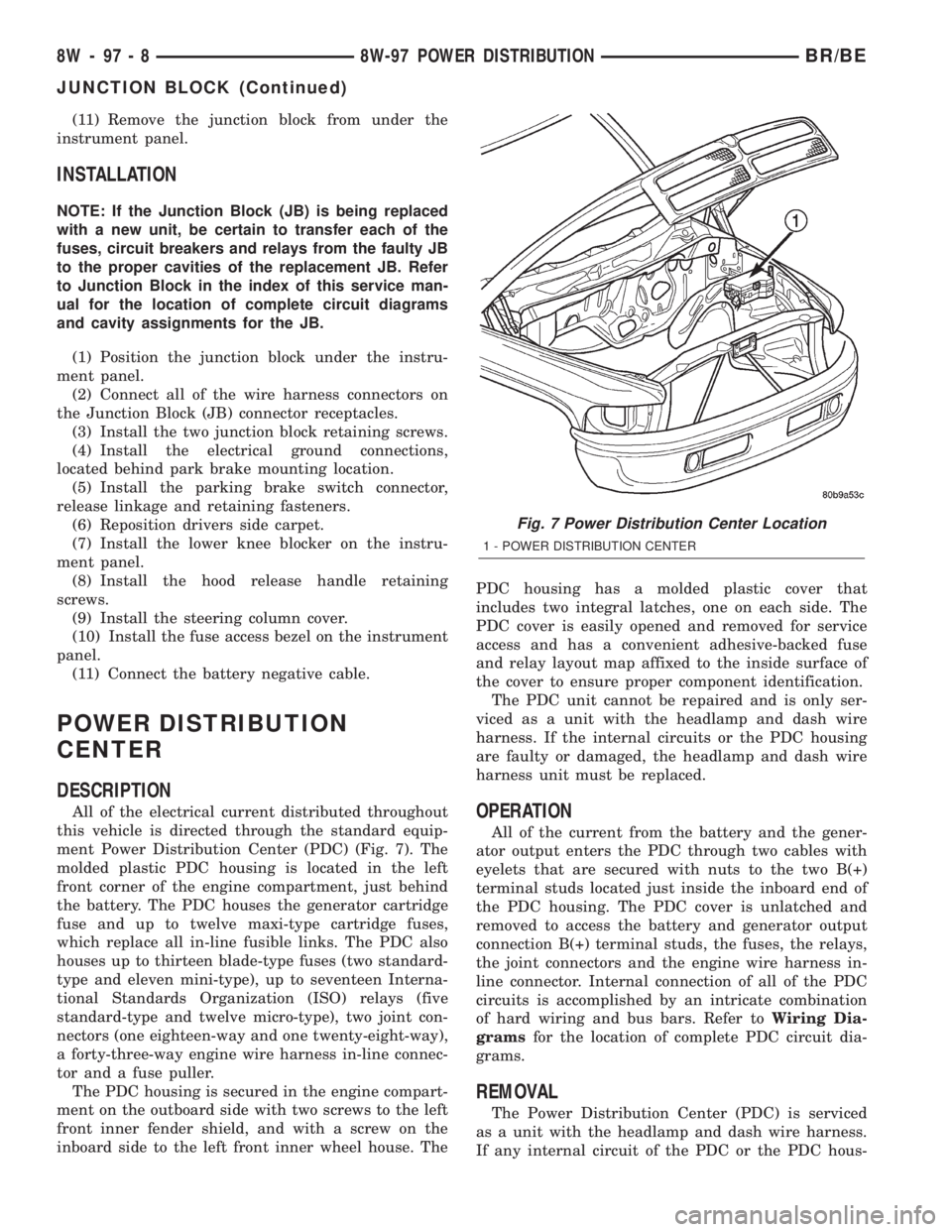
All of the electrical current distributed throughout
this vehicle is directed through the standard equip-
ment Power Distribution Center (PDC) (Fig. 7). The
molded plastic PDC housing is located in the left
front corner of the engine compartment, just behind
the battery. The PDC houses the generator cartridge
fuse and up to twelve maxi-type cartridge fuses,
which replace all in-line fusible links. The PDC also
houses up to thirteen blade-type fuses (two standard-
type and eleven mini-type), up to seventeen Interna-
tional Standards Organization (ISO) relays (five
standard-type and twelve micro-type), two joint con-
nectors (one eighteen-way and one twenty-eight-way),
a forty-three-way engine wire harness in-line connec-
tor and a fuse puller.
The PDC housing is secured in the engine compart-
ment on the outboard side with two screws to the left
front inner fender shield, and with a screw on the
inboard side to the left front inner wheel house. ThePDC housing has a molded plastic cover that
includes two integral latches, one on each side. The
PDC cover is easily opened and removed for service
access and has a convenient adhesive-backed fuse
and relay layout map affixed to the inside surface of
the cover to ensure proper component identification.
The PDC unit cannot be repaired and is only ser-
viced as a unit with the headlamp and dash wire
harness. If the internal circuits or the PDC housing
are faulty or damaged, the headlamp and dash wire
harness unit must be replaced.OPERATION
All of the current from the battery and the gener-
ator output enters the PDC through two cables with
eyelets that are secured with nuts to the two B(+)
terminal studs located just inside the inboard end of
the PDC housing. The PDC cover is unlatched and
removed to access the battery and generator output
connection B(+) terminal studs, the fuses, the relays,
the joint connectors and the engine wire harness in-
line connector. Internal connection of all of the PDC
circuits is accomplished by an intricate combination
of hard wiring and bus bars. Refer toWiring Dia-
gramsfor the location of complete PDC circuit dia-
grams.
REMOVAL
The Power Distribution Center (PDC) is serviced
as a unit with the headlamp and dash wire harness.
If any internal circuit of the PDC or the PDC hous-
Fig. 7 Power Distribution Center Location
1 - POWER DISTRIBUTION CENTER
8W - 97 - 8 8W-97 POWER DISTRIBUTIONBR/BE
JUNCTION BLOCK (Continued)
Page 1068 of 2255
ing is faulty or damaged, the entire PDC and head-
lamp and dash wire harness unit must be replaced.
(1) Disconnect and isolate the battery negative
cable.
(2) Disconnect each of the headlamp and dash wire
harness connectors. Refer toConnector Locations
in Wiring for the location of more information on the
headlamp and dash wire harness connector locations.
(3) Remove all of the fasteners that secure each of
the headlamp and dash wire harness ground eyelets
to the vehicle body and chassis components. Refer to
Connector Locationsin Wiring for the location of
more information on the ground eyelet locations.
(4) Disengage each of the retainers that secure the
headlamp and dash wire harness to the vehicle body
and chassis components. Refer toConnector Loca-
tionsin Wiring for the location of more information
on the headlamp and dash wire harness retainer
locations.
(5) Unlatch and remove the cover from the PDC.
(6) Remove the screw that secures the engine wire
harness in-line connector to the PDC and disconnect
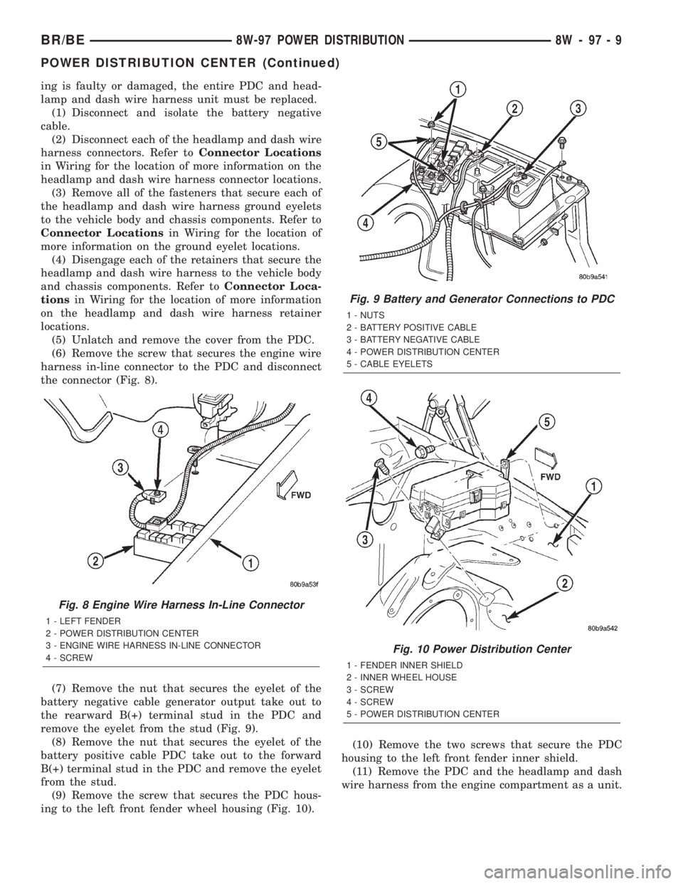
the connector (Fig. 8).
(7) Remove the nut that secures the eyelet of the
battery negative cable generator output take out to
the rearward B(+) terminal stud in the PDC and
remove the eyelet from the stud (Fig. 9).
(8) Remove the nut that secures the eyelet of the
battery positive cable PDC take out to the forward
B(+) terminal stud in the PDC and remove the eyelet
from the stud.
(9) Remove the screw that secures the PDC hous-
ing to the left front fender wheel housing (Fig. 10).(10) Remove the two screws that secure the PDC
housing to the left front fender inner shield.
(11) Remove the PDC and the headlamp and dash
wire harness from the engine compartment as a unit.
Fig. 8 Engine Wire Harness In-Line Connector
1 - LEFT FENDER
2 - POWER DISTRIBUTION CENTER
3 - ENGINE WIRE HARNESS IN-LINE CONNECTOR
4 - SCREW
Fig. 9 Battery and Generator Connections to PDC
1 - NUTS
2 - BATTERY POSITIVE CABLE
3 - BATTERY NEGATIVE CABLE
4 - POWER DISTRIBUTION CENTER
5 - CABLE EYELETS
Fig. 10 Power Distribution Center
1 - FENDER INNER SHIELD
2 - INNER WHEEL HOUSE
3 - SCREW
4 - SCREW
5 - POWER DISTRIBUTION CENTER
BR/BE8W-97 POWER DISTRIBUTION 8W - 97 - 9
POWER DISTRIBUTION CENTER (Continued)
Page 1069 of 2255
INSTALLATION
The Power Distribution Center (PDC) is serviced
as a unit with the headlamp and dash wire harness.
If any internal circuit of the PDC or the PDC hous-
ing is faulty or damaged, the entire PDC and head-
lamp and dash wire harness unit must be replaced.
NOTE: If the PDC is being replaced with a new unit,
be certain to transfer each of the blade-type fuses,
cartridge fuses and relays from the faulty PDC to
the proper cavities of the replacement PDC. Refer
to Power Distribution in the index of this service
manual for the location of complete PDC circuit dia-
grams and cavity assignments.
(1) Position the PDC and the headlamp and dash
wire harness unit in the engine compartment.
(2) Install and tighten the two screws that secure
the PDC housing to the left front fender inner shield.
Tighten the screws to 8.4 N´m (75 in. lbs.).
(3) Install and tighten the screw that secures the
PDC housing to the left front fender wheel housing.
Tighten the screw to 2.2 N´m (20 in. lbs.).
(4) Install the eyelet of the battery positive cable
PDC take out onto the forward B(+) terminal stud in
the PDC.
(5) Install and tighten the nut that secures the
eyelet of the battery positive cable PDC take out to
the forward B(+) terminal stud in the PDC. Tighten
the nut to 8.4 N´m (75 in. lbs.).
(6) Install the eyelet of the battery negative cable
generator output take out onto the rearward B(+) ter-
minal stud in the PDC.
(7) Install and tighten the nut that secures the
eyelet of the battery negative cable generator output
take out to the rearward B(+) terminal stud in the
PDC. Tighten the nut to 75 in. lbs.
(8) Reconnect the engine wire harness in-line con-
nector to the PDC.
(9) Install and tighten the screw that secures the
engine wire harness in-line connector to the PDC.
Tighten the screw until a distinct audible click is
heard.
(10) Install and latch the cover onto the PDC.
(11) Engage each of the retainers that secure the
headlamp and dash wire harness to the vehicle body
and chassis components. Refer toConnector Loca-
tionsin Wiring for the location of more information
on the headlamp and dash wire harness retainer
locations.
(12) Install all of the fasteners that secure each of
the headlamp and dash wire harness ground eyelets
to the vehicle body and chassis components. Refer to
Connector Locationsin Wiring for the location of
more information on the ground eyelet locations.(13) Reconnect each of the headlamp and dash
wire harness connectors. Refer toConnector Loca-
tionsin Wiring for the location of more information
on the headlamp and dash wire harness connector
locations.
(14) Reconnect the battery negative cable.
POWER OUTLET
DESCRIPTION
Two power outlets are installed in the vehicle. One
in the instrument panel next to the cigar lighter and
the other in the right rear quarter trim panel. The
power outlet bases are secured by a snap fit within
the instrument panel or trim panel. A plastic protec-
tive cap snaps into the power outlet base when the
power outlet is not being used, and hangs from the
power outlet base mount by an integral bail strap
while the power outlet is in use.
The power outlet receptacle unit and the accessory
power outlet protective cap are available for service.
The power outlet receptacle cannot be repaired and,
if faulty or damaged, it must be replaced.
OPERATION
The power outlet base or receptacle shell is con-
nected to ground, and an insulated contact in the
bottom of the shell is connected to battery current.
The power outlet receives battery voltage from a fuse
in the Junction Block at all times.
While the power outlet is very similar to a cigar
lighter base unit, it does not include the two small
spring-clip retainers inside the bottom of the recepta-
cle shell that are used to secure the cigar lighter
heating element to the insulated contact.
DIAGNOSIS AND TESTING - POWER OUTLET
For complete circuit diagrams, refer toPower
Outletin Wiring Diagrams.
(1) Check the fused B(+) fuse in the junction block.
If OK, go to Step 2. If not OK, repair the shorted cir-
cuit or component as required and replace the faulty
fuse.
(2) Check for battery voltage at the fused B(+) fuse
in the junction block. If OK, go to Step 3. If not OK,
repair the open fused B(+) circuit to the battery as
required.
(3) Remove the plastic protective cap from the
power outlet receptacle. Check for continuity between
the inside circumference of the power outlet recepta-
cle and a good ground. There should be continuity. If
OK, go to Step 4. If not OK, go to Step 5.
(4) Check for battery voltage at the insulated con-
tact located at the back of the power outlet recepta-
cle. If not OK, go to Step 5.
8W - 97 - 10 8W-97 POWER DISTRIBUTIONBR/BE
POWER DISTRIBUTION CENTER (Continued)
Page 1071 of 2255
(4) Press firmly on the cigar lighter or power out-
let receptacle base until the retaining bosses of the
mount are fully engaged in their receptacles.
(5) Install the cigar lighter knob and element into
the cigar lighter receptacle base, or the protective cap
into the power outlet receptacle base.
(6) Reconnect the battery negative cable.
HORN RELAY
DESCRIPTION
The horn relay is a International Standards Orga-
nization (ISO) micro-relay. The terminal designations
and functions are the same as a conventional ISO
relay. However, the micro-relay terminal orientation
(or footprint) is different, current capacity is lower,
and the relay case dimensions are smaller than those
of the conventional ISO relay.
The horn relay is a electromechanical device that
switches battery current to the horn when the horn
switch or when the high-line or premium Central
Timer Module (CTM) grounds the relay coil. See
Horn Relay in the Diagnosis and Testing section of
this group for more information.
The horn relay is located in the Power Distribution
Center (PDC), in the engine compartment. Refer to
the PDC label for relay identification and location.
If a problem is encountered with a continuously
sounding horn, it can usually be quickly resolved by
removing the horn relay from the PDC until further
diagnosis is completed.
The horn relay cannot be repaired and, if faulty or
damaged, it must be replaced.
DIAGNOSIS AND TESTING - HORN RELAY
The headlamp (or security) relay and the horn
relay are located in the Power Distribution Center
(PDC) in the engine compartment. Each of these
relays can be tested as described in the following pro-
cedure, however the circuits they are used in do vary.
To test the relay circuits, refer to the circuit descrip-
tions and diagrams in Wiring Diagrams.
WARNING: ON VEHICLES EQUIPPED WITH AIR-
BAGS, REFER TO THE RESTRAINTS SECTION OF
THE SERVICE MANUAL BEFORE ATTEMPTING ANY
STEERING WHEEL, STEERING COLUMN, OR
INSTRUMENT PANEL COMPONENT DIAGNOSIS OR
SERVICE. FAILURE TO TAKE THE PROPER PRE-
CAUTIONS COULD RESULT IN ACCIDENTAL AIR-
BAG DEPLOYMENT AND POSSIBLE PERSONAL
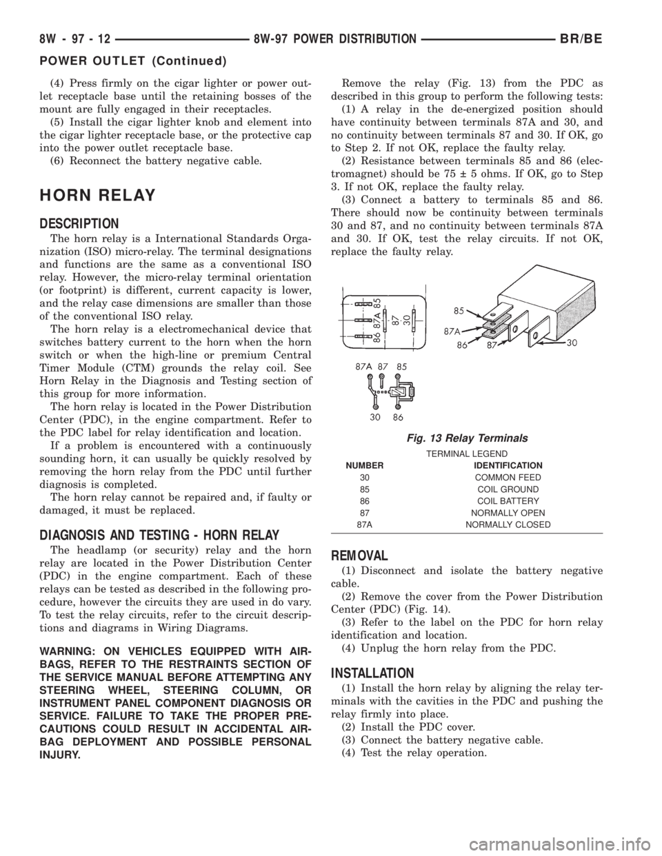
INJURY.Remove the relay (Fig. 13) from the PDC as
described in this group to perform the following tests:
(1) A relay in the de-energized position should
have continuity between terminals 87A and 30, and
no continuity between terminals 87 and 30. If OK, go
to Step 2. If not OK, replace the faulty relay.
(2) Resistance between terminals 85 and 86 (elec-
tromagnet) should be 75 5 ohms. If OK, go to Step
3. If not OK, replace the faulty relay.
(3) Connect a battery to terminals 85 and 86.
There should now be continuity between terminals
30 and 87, and no continuity between terminals 87A
and 30. If OK, test the relay circuits. If not OK,
replace the faulty relay.REMOVAL
(1) Disconnect and isolate the battery negative
cable.
(2) Remove the cover from the Power Distribution
Center (PDC) (Fig. 14).
(3) Refer to the label on the PDC for horn relay
identification and location.
(4) Unplug the horn relay from the PDC.
INSTALLATION
(1) Install the horn relay by aligning the relay ter-
minals with the cavities in the PDC and pushing the
relay firmly into place.
(2) Install the PDC cover.
(3) Connect the battery negative cable.
(4) Test the relay operation.
Fig. 13 Relay Terminals
TERMINAL LEGEND
NUMBER IDENTIFICATION
30 COMMON FEED
85 COIL GROUND
86 COIL BATTERY
87 NORMALLY OPEN
87A NORMALLY CLOSED
8W - 97 - 12 8W-97 POWER DISTRIBUTIONBR/BE
POWER OUTLET (Continued)
Page 1082 of 2255
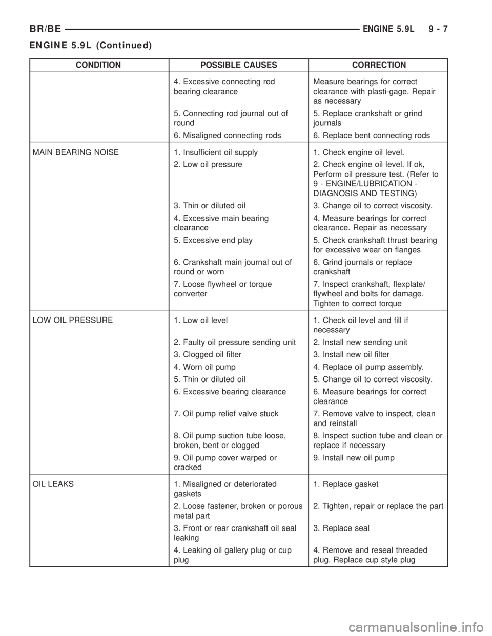
CONDITION POSSIBLE CAUSES CORRECTION
4. Excessive connecting rod
bearing clearanceMeasure bearings for correct
clearance with plasti-gage. Repair
as necessary
5. Connecting rod journal out of
round5. Replace crankshaft or grind
journals
6. Misaligned connecting rods 6. Replace bent connecting rods
MAIN BEARING NOISE 1. Insufficient oil supply 1. Check engine oil level.
2. Low oil pressure 2. Check engine oil level. If ok,
Perform oil pressure test. (Refer to
9 - ENGINE/LUBRICATION -
DIAGNOSIS AND TESTING)
3. Thin or diluted oil 3. Change oil to correct viscosity.
4. Excessive main bearing
clearance4. Measure bearings for correct
clearance. Repair as necessary
5. Excessive end play 5. Check crankshaft thrust bearing
for excessive wear on flanges
6. Crankshaft main journal out of
round or worn6. Grind journals or replace
crankshaft
7. Loose flywheel or torque
converter7. Inspect crankshaft, flexplate/
flywheel and bolts for damage.
Tighten to correct torque
LOW OIL PRESSURE 1. Low oil level 1. Check oil level and fill if
necessary
2. Faulty oil pressure sending unit 2. Install new sending unit
3. Clogged oil filter 3. Install new oil filter
4. Worn oil pump 4. Replace oil pump assembly.
5. Thin or diluted oil 5. Change oil to correct viscosity.
6. Excessive bearing clearance 6. Measure bearings for correct
clearance
7. Oil pump relief valve stuck 7. Remove valve to inspect, clean
and reinstall
8. Oil pump suction tube loose,
broken, bent or clogged8. Inspect suction tube and clean or
replace if necessary
9. Oil pump cover warped or
cracked9. Install new oil pump
OIL LEAKS 1. Misaligned or deteriorated
gaskets1. Replace gasket
2. Loose fastener, broken or porous
metal part2. Tighten, repair or replace the part
3. Front or rear crankshaft oil seal
leaking3. Replace seal
4. Leaking oil gallery plug or cup
plug4. Remove and reseal threaded
plug. Replace cup style plug
BR/BEENGINE 5.9L 9 - 7
ENGINE 5.9L (Continued)
Page 1092 of 2255
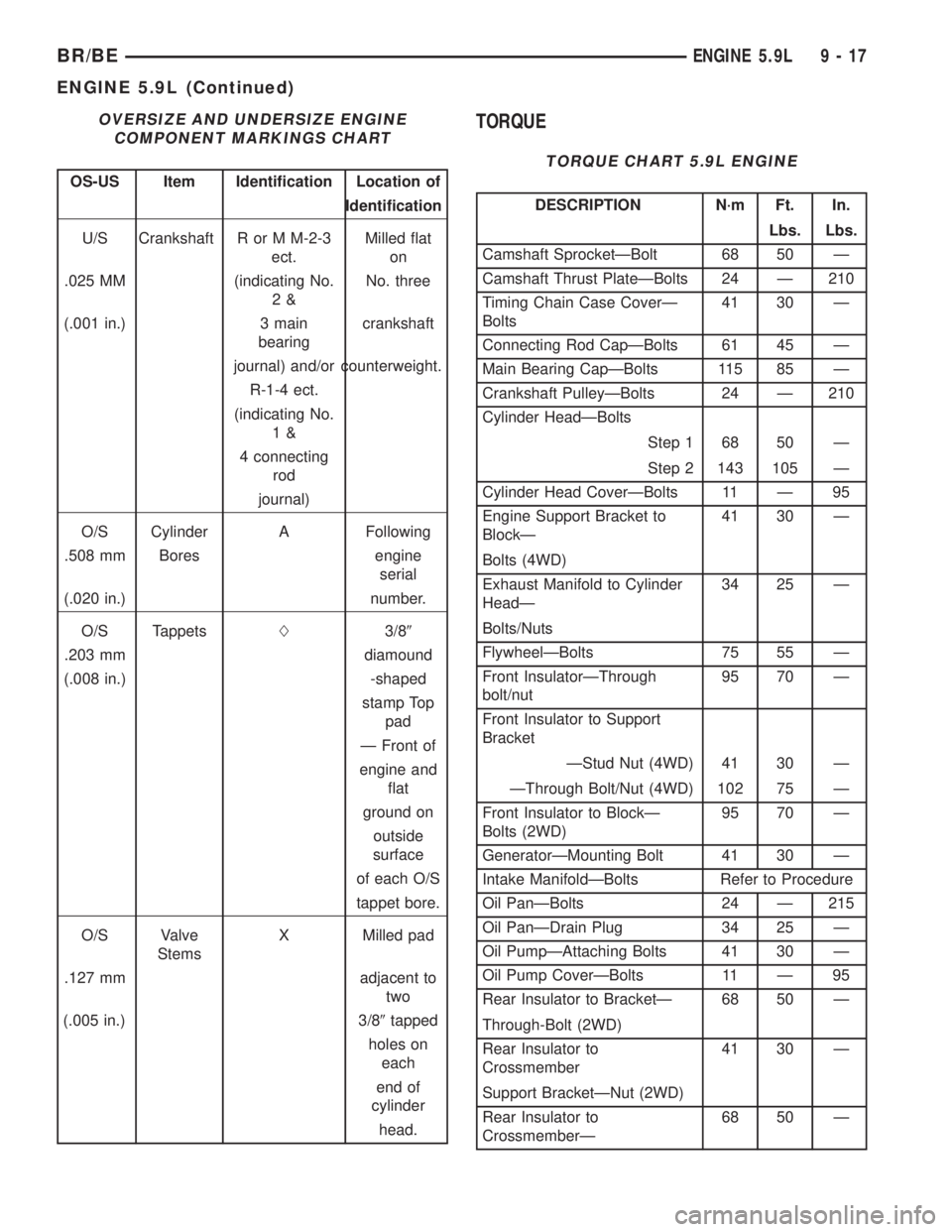
OVERSIZE AND UNDERSIZE ENGINE
COMPONENT MARKINGS CHART
OS-US Item Identification Location of
Identification
U/S Crankshaft R or M M-2-3
ect.Milled flat
on
.025 MM (indicating No.
2&No. three
(.001 in.) 3 main
bearingcrankshaft
journal) and/or counterweight.
R-1-4 ect.
(indicating No.
1&
4 connecting
rod
journal)
O/S Cylinder A Following
.508 mm Bores engine
serial
(.020 in.) number.
O/S TappetsL3/89
.203 mm diamound
(.008 in.) -shaped
stamp Top
pad
Ð Front of
engine and
flat
ground on
outside
surface
of each O/S
tappet bore.
O/S Valve
StemsX Milled pad
.127 mm adjacent to
two
(.005 in.) 3/89tapped
holes on
each
end of
cylinder
head.
TORQUE
TORQUE CHART 5.9L ENGINE
DESCRIPTION N´m Ft. In.
Lbs. Lbs.
Camshaft SprocketÐBolt 68 50 Ð
Camshaft Thrust PlateÐBolts 24 Ð 210
Timing Chain Case CoverÐ
Bolts41 30 Ð
Connecting Rod CapÐBolts 61 45 Ð
Main Bearing CapÐBolts 115 85 Ð
Crankshaft PulleyÐBolts 24 Ð 210
Cylinder HeadÐBolts
Step 1 68 50 Ð
Step 2 143 105 Ð
Cylinder Head CoverÐBolts 11 Ð 95
Engine Support Bracket to
BlockÐ41 30 Ð
Bolts (4WD)
Exhaust Manifold to Cylinder
HeadÐ34 25 Ð
Bolts/Nuts
FlywheelÐBolts 75 55 Ð
Front InsulatorÐThrough
bolt/nut95 70 Ð
Front Insulator to Support
Bracket
ÐStud Nut (4WD) 41 30 Ð
ÐThrough Bolt/Nut (4WD) 102 75 Ð
Front Insulator to BlockÐ
Bolts (2WD)95 70 Ð
GeneratorÐMounting Bolt 41 30 Ð
Intake ManifoldÐBolts Refer to Procedure
Oil PanÐBolts 24 Ð 215
Oil PanÐDrain Plug 34 25 Ð
Oil PumpÐAttaching Bolts 41 30 Ð
Oil Pump CoverÐBolts 11 Ð 95
Rear Insulator to BracketÐ 68 50 Ð
Through-Bolt (2WD)
Rear Insulator to
Crossmember41 30 Ð
Support BracketÐNut (2WD)
Rear Insulator to
CrossmemberÐ68 50 Ð
BR/BEENGINE 5.9L 9 - 17
ENGINE 5.9L (Continued)
Page 1104 of 2255
INSTALLATIONÐCAMSHAFT
(1) Lubricate camshaft lobes and camshaft bearing
journals and insert the camshaft to within 51 mm (2
inches) of its final position in cylinder block.
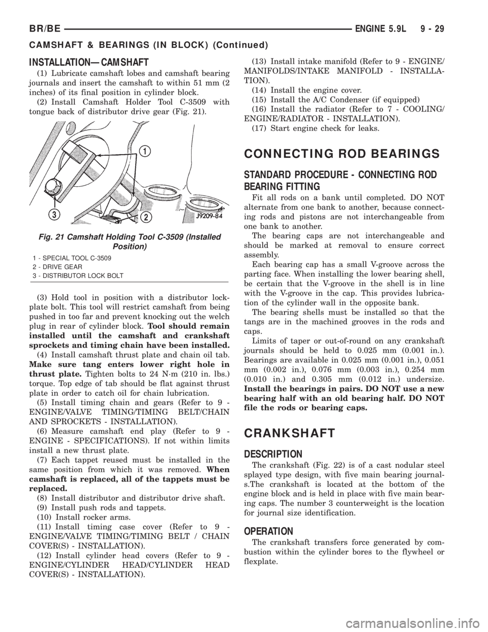
(2) Install Camshaft Holder Tool C-3509 with
tongue back of distributor drive gear (Fig. 21).
(3) Hold tool in position with a distributor lock-
plate bolt. This tool will restrict camshaft from being
pushed in too far and prevent knocking out the welch
plug in rear of cylinder block.Tool should remain
installed until the camshaft and crankshaft
sprockets and timing chain have been installed.
(4) Install camshaft thrust plate and chain oil tab.
Make sure tang enters lower right hole in
thrust plate.Tighten bolts to 24 N´m (210 in. lbs.)
torque. Top edge of tab should be flat against thrust
plate in order to catch oil for chain lubrication.
(5) Install timing chain and gears (Refer to 9 -
ENGINE/VALVE TIMING/TIMING BELT/CHAIN
AND SPROCKETS - INSTALLATION).
(6) Measure camshaft end play (Refer to 9 -
ENGINE - SPECIFICATIONS). If not within limits
install a new thrust plate.
(7) Each tappet reused must be installed in the
same position from which it was removed.When
camshaft is replaced, all of the tappets must be
replaced.
(8) Install distributor and distributor drive shaft.
(9) Install push rods and tappets.
(10) Install rocker arms.
(11) Install timing case cover (Refer to 9 -
ENGINE/VALVE TIMING/TIMING BELT / CHAIN
COVER(S) - INSTALLATION).
(12) Install cylinder head covers (Refer to 9 -
ENGINE/CYLINDER HEAD/CYLINDER HEAD
COVER(S) - INSTALLATION).(13) Install intake manifold (Refer to 9 - ENGINE/
MANIFOLDS/INTAKE MANIFOLD - INSTALLA-
TION).
(14) Install the engine cover.
(15) Install the A/C Condenser (if equipped)
(16) Install the radiator (Refer to 7 - COOLING/
ENGINE/RADIATOR - INSTALLATION).
(17) Start engine check for leaks.
CONNECTING ROD BEARINGS
STANDARD PROCEDURE - CONNECTING ROD
BEARING FITTING
Fit all rods on a bank until completed. DO NOT
alternate from one bank to another, because connect-
ing rods and pistons are not interchangeable from
one bank to another.
The bearing caps are not interchangeable and
should be marked at removal to ensure correct
assembly.
Each bearing cap has a small V-groove across the
parting face. When installing the lower bearing shell,
be certain that the V-groove in the shell is in line
with the V-groove in the cap. This provides lubrica-
tion of the cylinder wall in the opposite bank.
The bearing shells must be installed so that the
tangs are in the machined grooves in the rods and
caps.
Limits of taper or out-of-round on any crankshaft
journals should be held to 0.025 mm (0.001 in.).
Bearings are available in 0.025 mm (0.001 in.), 0.051
mm (0.002 in.), 0.076 mm (0.003 in.), 0.254 mm
(0.010 in.) and 0.305 mm (0.012 in.) undersize.
Install the bearings in pairs. DO NOT use a new
bearing half with an old bearing half. DO NOT
file the rods or bearing caps.
CRANKSHAFT
DESCRIPTION
The crankshaft (Fig. 22) is of a cast nodular steel
splayed type design, with five main bearing journal-
s.The crankshaft is located at the bottom of the
engine block and is held in place with five main bear-
ing caps. The number 3 counterweight is the location
for journal size identification.
OPERATION
The crankshaft transfers force generated by com-
bustion within the cylinder bores to the flywheel or
flexplate.
Fig. 21 Camshaft Holding Tool C-3509 (Installed
Position)
1 - SPECIAL TOOL C-3509
2 - DRIVE GEAR
3 - DISTRIBUTOR LOCK BOLT
BR/BEENGINE 5.9L 9 - 29
CAMSHAFT & BEARINGS (IN BLOCK) (Continued)