2002 DODGE RAM wheel
[x] Cancel search: wheelPage 644 of 2255
WIPERS/WASHERS
TABLE OF CONTENTS
page page
WIPERS/WASHERS
DESCRIPTION..........................1
OPERATION............................2
DIAGNOSIS AND TESTING - WIPER &
WASHER SYSTEM.....................3
CLEANING - WIPER & WASHER SYSTEM.....6
INSPECTION - WIPER & WASHER SYSTEM . . . 6
WASHER FLUID LEVEL SWITCH
DESCRIPTION..........................7
OPERATION............................7
REMOVAL.............................8
INSTALLATION..........................8
WASHER HOSES/TUBES
DESCRIPTION..........................8
OPERATION............................8
WASHER NOZZLE
DESCRIPTION..........................9
OPERATION............................9
REMOVAL.............................9
INSTALLATION..........................9
WASHER PUMP/MOTOR
DESCRIPTION..........................9
OPERATION............................9
REMOVAL.............................10
INSTALLATION.........................10
WASHER RESERVOIR
DESCRIPTION.........................10OPERATION...........................10
REMOVAL.............................10
INSTALLATION.........................11
WIPER ARM
DESCRIPTION.........................11
OPERATION...........................11
REMOVAL.............................12
INSTALLATION.........................12
WIPER BLADE
DESCRIPTION.........................12
OPERATION...........................13
REMOVAL.............................13
INSTALLATION.........................13
WIPER MODULE
DESCRIPTION.........................13
OPERATION...........................14
REMOVAL.............................14
INSTALLATION.........................14
WIPER RELAY
DESCRIPTION.........................15
OPERATION...........................15
DIAGNOSIS AND TESTING - WIPER RELAY . . . 16
REMOVAL.............................17
INSTALLATION.........................17
WIPERS/WASHERS
DESCRIPTION
An electrically operated intermittent wiper and
washer system is standard factory-installed safety
equipment on this model. The wiper and washer sys-
tem includes the following major components, which
are described in further detail elsewhere in this ser-
vice information:
²Central Timer Module- The Central Timer
Module (CTM) is located under the driver side end of
the instrument panel, inboard of the instrument
panel steering column opening. A base version of the
CTM is used on base models of this vehicle. The base
version of the CTM combines the functions of a
chime module and an intermittent wipe module in a
single unit. The high-line version of the CTM is used
on high-line vehicles. The high-line CTM provides all
of the functions of the base version of the CTM, but
also is used to control and integrate many additionalelectronic functions and features included on high-
line models. The premium version of the CTM is the
same as the high-line version, but is used only on
models equipped with the heated seat option. The
high-line and premium versions of the CTM contain
integrated circuitry, a central processing unit and the
programming to provide all of the proper wiper and
washer system features based upon the monitored
inputs. The high-line and premium CTM circuitry
monitors hard wired switch inputs, as well as mes-
sage inputs received from other vehicle electronic
modules on the Chrysler Collision Detection (CCD)
data bus network. (Refer to 8 - ELECTRICAL/ELEC-
TRONIC CONTROL MODULES/BODY CONTROL/
CENTRAL TIMER MODULE - DESCRIPTION).
²Multi-Function Switch- The multi-function
switch is secured to the left side of the steering col-
umn, just below the steering wheel. Only the control
stalk for the multi-function switch is visible, the
remainder of the switch is concealed beneath the
steering column shrouds. The multi-function switch
BR/BEWIPERS/WASHERS 8R - 1
Page 645 of 2255
contains all of the switches for both the wiper and
washer systems.
²Washer Fluid Level Switch- The washer fluid
level switch is located in a dedicated hole on the
lower rear side of the washer reservoir, above the
washer pump/motor unit near the left front corner of
the engine compartment.
²Washer Nozzles- The dual fluidic washer noz-
zles are secured with integral snap features to dedi-
cated openings in the cowl plenum cover/grille panel
located near the base of the windshield. The washer
plumbing fittings for the washer nozzles are con-
cealed beneath the cowl plenum cover/grille panel.
²Washer Pump/Motor- The washer pump/mo-
tor unit is located in a dedicated hole on the lower
rear side of the washer reservoir near the left front
corner of the engine compartment.
²Washer Reservoir- The washer reservoir is
secured to the left side of the radiator fan shroud in
the left front corner of the engine compartment.
²Wiper Arms- The two wiper arms are secured
to the two wiper pivots, which extend through the
cowl plenum cover/grille panel located near the base
of the windshield.
²Wiper Blades- The two wiper blades are
secured to the two wiper arms, and are parked on
the glass near the bottom of the windshield when the
wiper system is not in operation.
²Wiper Module- The wiper pivots are the only
visible components of the wiper module. The remain-
der of the module is concealed within the cowl ple-
num beneath the cowl plenum cover/grille panel. The
wiper module includes the module bracket, the single
wiper motor, the wiper linkage, and the two wiper
pivots.
²Wiper Relay- The wiper relay is located in the
Power Distribution Center (PDC) in the engine com-
partment near the battery.
Features of the wiper and washer system include
the following:
²Continuous Wipe Modes- The two-speed
wiper motor and the internal circuitry of the multi-
function switch work in concert to provide two con-
tinuous wipe cycles, low speed or high speed.
²Intermittent Wipe Mode- The internal cir-
cuitry of the multi-function switch, the CTM, and the
wiper relay work in concert to provide an intermit-
tent wipe mode with multiple delay interval selec-
tions. On models with a high-line or premium CTM,
the CTM also automatically adjusts each manually
selected delay interval to compensate for vehicle
speed.
²Washer Mode- When the washer system is
activated with the multi-function switch while the
wiper system is operating, washer fluid will be dis-
pensed onto the windshield glass through the washernozzles for as long as the washer pump/motor is
energized.
²Wipe-After-Wash Mode- The internal circuitry
of the CTM provides a wipe-after-wash feature
which, if the wipers are turned Off, will operate the
washer pump/motor and the wipers for as long as the
washer system is activated, then provide several
additional wipe cycles after the washer system is
deactivated before parking the wiper blades near the
base of the windshield.
Hard wired circuitry connects the wiper and
washer system components to the electrical system of
the vehicle. These hard wired circuits are integral to
several wire harnesses, which are routed throughout
the vehicle and retained by many different methods.
These circuits may be connected to each other, to the
vehicle electrical system and to the wiper and washer
system components through the use of a combination
of soldered splices, splice block connectors, and many
different types of wire harness terminal connectors
and insulators. Refer to the appropriate wiring infor-
mation. The wiring information includes wiring dia-
grams, proper wire and connector repair procedures,
further details on wire harness routing and reten-
tion, as well as pin-out and location views for the
various wire harness connectors, splices and grounds.
OPERATION
The wiper and washer system is intended to pro-
vide the vehicle operator with a convenient, safe, and
reliable means of maintaining visibility through the
windshield glass. The various components of this sys-
tem are designed to convert electrical energy pro-
duced by the vehicle electrical system into the
mechanical action of the wiper blades to wipe the
outside surface of the glass, as well as into the
hydraulic action of the washer system to apply
washer fluid stored in an on-board reservoir to the
area of the glass to be wiped. When combined, these
components provide the means to effectively main-
tain clear visibility for the vehicle operator by remov-
ing excess accumulations of rain, snow, bugs, mud, or
other minor debris from the outside windshield glass
surface that might be encountered while driving the
vehicle under numerous types of inclement operating
conditions. The vehicle operator initiates all wiper
and washer system functions with the multi-function
switch control stalk that extends from the left side of
the steering column, just below the steering wheel.
Rotating the knob on the end of the multi-function
switch control stalk selects the desired wiper system
operating mode. The wiper system allows the vehicle
operator to select from two continuous wiper speeds,
Hi or Lo, or one of several intermittent wipe Delay
mode intervals. Pushing the button on the end of the
control stalk downwards towards the steering column
8R - 2 WIPERS/WASHERSBR/BE
WIPERS/WASHERS (Continued)
Page 647 of 2255
However, these tests may not prove conclusive in the
diagnosis of this system on models equipped with a
high-line or premium Central Timer Module (CTM).
In order to obtain conclusive testing of the wiper sys-
tem on models with a high-line or premium CTM, the
Chrysler Collision Detection (CCD) data bus network
and all of the electronic modules that provide inputs
to or receive outputs from the wiper system compo-
nents must be checked. The most reliable, efficient,
and accurate means to diagnose the wiper system on
models with a high-line or premium CTM requires
the use of a DRBIIItscan tool. Refer to the appro-
priate diagnostic information. The DRBIIItscan tool
can provide confirmation that the CCD data bus is
functional, that all of the electronic modules are
sending and receiving the proper messages on the
CCD data bus, and that the wiper relay is being sent
the proper hard wired outputs by the CTM for it to
perform its wiper system functions.
WARNING: ON VEHICLES EQUIPPED WITH AIR-
BAGS, DISABLE THE AIRBAG SYSTEM BEFORE
ATTEMPTING ANY STEERING WHEEL, STEERING
COLUMN, OR INSTRUMENT PANEL COMPONENT
DIAGNOSIS OR SERVICE. DISCONNECT AND ISO-
LATE THE BATTERY NEGATIVE (GROUND) CABLE,
THEN WAIT TWO MINUTES FOR THE AIRBAG SYS-
TEM CAPACITOR TO DISCHARGE BEFORE PER-
FORMING FURTHER DIAGNOSIS OR SERVICE. THIS
IS THE ONLY SURE WAY TO DISABLE THE AIRBAG
SYSTEM. FAILURE TO TAKE THE PROPER PRE-
CAUTIONS COULD RESULT IN ACCIDENTAL AIR-
BAG DEPLOYMENT AND POSSIBLE PERSONAL
INJURY.
(1) Check the fused ignition switch output (run-
acc) fuse (Fuse6-25ampere) in the Junction Block
(JB). If OK, go to Step 2. If not OK, repair the
shorted circuit or component as required and replace
the faulty fuse.
(2) Turn the ignition switch to the On position.
Check for battery voltage at the fused ignition switch
output (run-acc) fuse (Fuse6-25ampere) in the JB.
If OK, go to Step 3. If not OK, repair the open fused
ignition switch output (run-acc) circuit between the
JB and the ignition switch as required.
(3) Turn the ignition switch to the Off position.
Disconnect and isolate the battery negative cable.
Disconnect the instrument panel wire harness con-
nector for the multi-function switch from the switch
connector receptacle. Reconnect the battery negative
cable. Turn the ignition switch to the On position.
Check for battery voltage at the fused ignition switch
output (run-acc) circuit cavity of the instrument
panel wire harness connector for the multi-function
switch. If OK, go to Step 4. If not OK, repair theopen fused ignition switch output circuit between the
multi-function switch and the JB as required.
(4) If the problem being diagnosed involves only
the intermittent wipe feature, go to Step 5. If the
problem being diagnosed involves all wiper modes, or
only the Low and/or High speed modes, go to Step 7.
(5) Turn the ignition switch to the Off position.
Disconnect and isolate the battery negative cable.
Disconnect the instrument panel wire harness con-
nector (Connector C1) for the Central Timer Module
(CTM) from the CTM connector receptacle. Check for
continuity between the wiper switch mode sense cir-
cuit cavities of the instrument panel wire harness
connector for the multi-function switch and the
instrument panel wire harness connector (Connector
C1) for the CTM. There should be continuity. If OK,
go to Step 6. If not OK, repair the open wiper switch
mode sense circuit between the multi-function switch
and the CTM as required.
(6) Check for continuity between the wiper switch
mode signal circuit cavities of the instrument panel
wire harness connector for the multi-function switch
and the instrument panel wire harness connector
(Connector C1) for the CTM. There should be conti-
nuity. If OK, proceed to the diagnosis for the wiper
relay. (Refer to 8 - ELECTRICAL/WIPERS/WASH-
ERS/WIPER RELAY - DIAGNOSIS AND TESTING).
If not OK, repair the open wiper switch mode signal
circuit between the multi-function switch and the
CTM as required.
(7) Check for continuity between the two wiper
switch low speed output circuit cavities of the instru-
ment panel wire harness connector for the multi-
function switch. There should be continuity. If OK, go
to Step 8. If not OK, repair the open wiper switch
low speed output circuit between the two cavities of
the instrument panel wire harness connector for the
multi-function switch as required.
(8) Test the multi-function switch continuity.
(Refer to 8 - ELECTRICAL/LAMPS/LIGHTING -
EXTERIOR/MULTI-FUNCTION SWITCH - DIAG-
NOSIS AND TESTING). If the multi-function switch
tests OK, reconnect the instrument panel wire har-
ness connector for the multi-function switch to the
switch connector receptacle and go to Step 9. If not
OK, replace the faulty multi-function switch and test
the wiper system operation again. If still not OK, go
to Step 9.
(9) Turn the ignition switch to the Off position.
Disconnect and isolate the battery negative cable.
Measure the resistance between the headlamp and
dash wire harness ground wire for the wiper motor
and a good ground. The meter should read zero
ohms. If OK, go to Step 10. If not OK, repair the
open ground circuit to ground (G100) as required.
8R - 4 WIPERS/WASHERSBR/BE
WIPERS/WASHERS (Continued)
Page 648 of 2255
(10) Disconnect the headlamp and dash wire har-
ness connector for the wiper module from the wiper
motor pigtail wire connector. Reconnect the battery
negative cable. Turn the ignition switch to the On
position. Place the multi-function switch in the posi-
tions indicated in the tests below, and check for bat-
tery voltage at the appropriate cavity of the
headlamp and dash wire harness connector for the
wiper motor.
(a) Check for battery voltage at the fused igni-
tion switch output (run-acc) circuit cavity of the
headlamp and dash wire harness connector for the
wiper module with the multi-function switch in
any position. If OK, go to Step b. If not OK, repair
the open fused ignition switch output (run-acc) cir-
cuit between the wiper module and the JB as
required.
(b) Check for battery voltage at the wiper switch
low speed output circuit cavity of the headlamp
and dash wire harness connector for the wiper
module with the multi-function switch in the Lo
position. If OK, go to Step c. If not OK, repair the
open wiper switch low speed output circuit between
the wiper module and the multi-function switch as
required.
(c) Check for battery voltage at the wiper switch
high speed output circuit cavity of the headlamp
and dash wire harness connector for the wiper
module with the multi-function switch in the Hi
position. If OK, go to Step d. If not OK, repair the
open wiper switch high speed output circuit
between the wiper module and the multi-function
switch as required.
(d) Check for battery voltage at the wiper park
switch sense circuit cavity of the headlamp and
dash wire harness connector for the wiper module
with the multi-function switch in the Lo or Hi posi-
tion, then move the switch to the Off position. The
meter should switch between battery voltage and
zero volts while the wipers are cycling. The meter
should read battery voltage when the switch is
first moved to the Off position until the wipers
park, and then read a steady zero volts. If not OK,
replace the faulty wiper module.
WASHER SYSTEM
The diagnosis found here addresses an electrically
inoperative washer system. If the washer pump/mo-
tor operates, but no washer fluid is emitted from the
washer nozzles, be certain to check the fluid level in
the reservoir. Also inspect the washer system compo-
nents as required. (Refer to 8 - ELECTRICAL/WIP-
ERS/WASHERS - INSPECTION). Refer to the
appropriate wiring information. The wiring informa-
tion includes wiring diagrams, proper wire and con-
nector repair procedures, details of wire harnessrouting and retention, connector pin-out information
and location views for the various wire harness con-
nectors, splices and grounds.
WARNING: ON VEHICLES EQUIPPED WITH AIR-
BAGS, DISABLE THE AIRBAG SYSTEM BEFORE
ATTEMPTING ANY STEERING WHEEL, STEERING
COLUMN, OR INSTRUMENT PANEL COMPONENT
DIAGNOSIS OR SERVICE. DISCONNECT AND ISO-
LATE THE BATTERY NEGATIVE (GROUND) CABLE,
THEN WAIT TWO MINUTES FOR THE AIRBAG SYS-
TEM CAPACITOR TO DISCHARGE BEFORE PER-
FORMING FURTHER DIAGNOSIS OR SERVICE. THIS
IS THE ONLY SURE WAY TO DISABLE THE AIRBAG
SYSTEM. FAILURE TO TAKE THE PROPER PRE-
CAUTIONS COULD RESULT IN ACCIDENTAL AIR-
BAG DEPLOYMENT AND POSSIBLE PERSONAL
INJURY.
(1) Turn the ignition switch to the On position.
Turn the multi-function switch wiper control knob to
the Lo or Hi speed position. Check whether the wip-
ers operate. If OK, go to Step 2. If not OK, repair the
wiper system as required before proceeding with the
following tests. Refer to WIPER SYSTEM .
(2) Turn the multi-function switch wiper control
knob to the Off position. Depress the washer button.
The washer pump should operate and the wipers
should operate for as long as the washer button is
depressed. The wipers should continue to operate for
about three sweep cycles after the button is released
before they park. If the wipers are OK, but the wash-
ers are not, go to Step 3. If the washers are OK, but
the wipers are not, go to Step 5.
(3) Turn the ignition switch to the Off position.
Disconnect and isolate the battery negative cable.
Disconnect the headlamp and dash wire harness con-
nector for the washer pump/motor from the motor
connector receptacle. Measure the resistance between
the ground circuit cavity of the headlamp and dash
wire harness connector for the washer pump/motor
and a good ground. The meter should read zero
ohms. If OK, go to Step 4. If not OK, repair the open
ground circuit to ground (G100) as required.
(4) Reconnect the battery negative cable. Turn the
ignition switch to the On position. With the washer
button depressed, check for battery voltage at the
washer switch output circuit cavity of the headlamp
and dash wire harness connector for the washer
pump/motor. If OK, replace the faulty washer pump/
motor. If not OK, repair the open washer switch out-
put circuit between the washer pump/motor and the
multi-function switch as required.
(5) Turn the ignition switch to the Off position.
Disconnect and isolate the battery negative cable.
Disconnect the instrument panel wire harness con-
nector (Connector C1) for the Central Timer Module
BR/BEWIPERS/WASHERS 8R - 5
WIPERS/WASHERS (Continued)
Page 650 of 2255
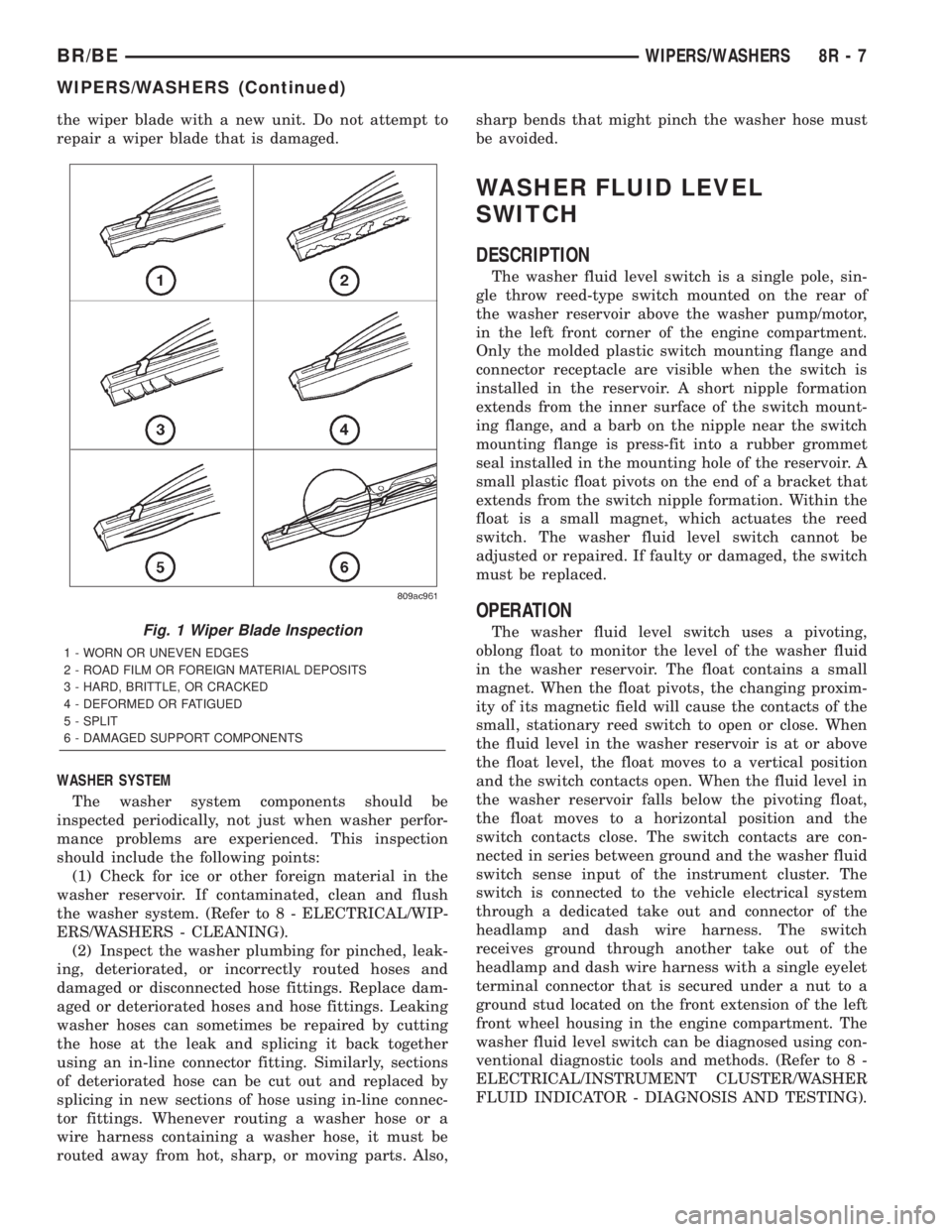
the wiper blade with a new unit. Do not attempt to
repair a wiper blade that is damaged.
WASHER SYSTEM
The washer system components should be
inspected periodically, not just when washer perfor-
mance problems are experienced. This inspection
should include the following points:
(1) Check for ice or other foreign material in the
washer reservoir. If contaminated, clean and flush
the washer system. (Refer to 8 - ELECTRICAL/WIP-
ERS/WASHERS - CLEANING).
(2) Inspect the washer plumbing for pinched, leak-
ing, deteriorated, or incorrectly routed hoses and
damaged or disconnected hose fittings. Replace dam-
aged or deteriorated hoses and hose fittings. Leaking
washer hoses can sometimes be repaired by cutting
the hose at the leak and splicing it back together
using an in-line connector fitting. Similarly, sections
of deteriorated hose can be cut out and replaced by
splicing in new sections of hose using in-line connec-
tor fittings. Whenever routing a washer hose or a
wire harness containing a washer hose, it must be
routed away from hot, sharp, or moving parts. Also,sharp bends that might pinch the washer hose must
be avoided.
WASHER FLUID LEVEL
SWITCH
DESCRIPTION
The washer fluid level switch is a single pole, sin-
gle throw reed-type switch mounted on the rear of
the washer reservoir above the washer pump/motor,
in the left front corner of the engine compartment.
Only the molded plastic switch mounting flange and
connector receptacle are visible when the switch is
installed in the reservoir. A short nipple formation
extends from the inner surface of the switch mount-
ing flange, and a barb on the nipple near the switch
mounting flange is press-fit into a rubber grommet
seal installed in the mounting hole of the reservoir. A
small plastic float pivots on the end of a bracket that
extends from the switch nipple formation. Within the
float is a small magnet, which actuates the reed
switch. The washer fluid level switch cannot be
adjusted or repaired. If faulty or damaged, the switch
must be replaced.
OPERATION
The washer fluid level switch uses a pivoting,
oblong float to monitor the level of the washer fluid
in the washer reservoir. The float contains a small
magnet. When the float pivots, the changing proxim-
ity of its magnetic field will cause the contacts of the
small, stationary reed switch to open or close. When
the fluid level in the washer reservoir is at or above
the float level, the float moves to a vertical position
and the switch contacts open. When the fluid level in
the washer reservoir falls below the pivoting float,
the float moves to a horizontal position and the
switch contacts close. The switch contacts are con-
nected in series between ground and the washer fluid
switch sense input of the instrument cluster. The
switch is connected to the vehicle electrical system
through a dedicated take out and connector of the
headlamp and dash wire harness. The switch
receives ground through another take out of the
headlamp and dash wire harness with a single eyelet
terminal connector that is secured under a nut to a
ground stud located on the front extension of the left
front wheel housing in the engine compartment. The
washer fluid level switch can be diagnosed using con-
ventional diagnostic tools and methods. (Refer to 8 -
ELECTRICAL/INSTRUMENT CLUSTER/WASHER
FLUID INDICATOR - DIAGNOSIS AND TESTING).Fig. 1 Wiper Blade Inspection
1 - WORN OR UNEVEN EDGES
2 - ROAD FILM OR FOREIGN MATERIAL DEPOSITS
3 - HARD, BRITTLE, OR CRACKED
4 - DEFORMED OR FATIGUED
5 - SPLIT
6 - DAMAGED SUPPORT COMPONENTS
BR/BEWIPERS/WASHERS 8R - 7
WIPERS/WASHERS (Continued)
Page 652 of 2255
be routed away from hot, sharp, or moving parts;
and, sharp bends that might pinch the hose must be
avoided.
WASHER NOZZLE
DESCRIPTION
The two washer nozzles have integral snap fea-
tures that secure them in dedicated holes in the cowl
plenum cover/grille panel located near the base of the
windshield. The domed upper surface of the washer
nozzle is visible on the top of the plenum cover/grille
panel, and the nozzle orifice is oriented towards the
windshield glass. The washer plumbing fittings for
the washer nozzles are concealed beneath the cowl
plenum cover/grille panel. These fluidic washer noz-
zles are constructed of molded plastic. The cowl ple-
num cover/grille panel must be removed from the
vehicle to access the nozzles for service. The washer
nozzles cannot be adjusted or repaired and, if faulty
or damaged, they must be replaced.
OPERATION
The two washer nozzles are designed to dispense
washer fluid into the wiper pattern area on the out-
side of the windshield glass. Pressurized washer fluid
is fed to each nozzle from the washer reservoir by the
washer pump/motor through rubber hoses, which are
attached to a barbed nipple on each washer nozzle
below the cowl plenum cover/grille panel. The washer
nozzles incorporate a fluidic design, which causes the
nozzle to emit the pressurized washer fluid as an
oscillating stream to more effectively cover a larger
area of the glass area to be cleaned.
REMOVAL
(1) Remove the cowl plenum cover/grille panel
from the cowl top. (Refer to 23 - BODY/EXTERIOR/
COWL GRILLE - REMOVAL).
(2) From the underside of the cowl plenum cover/
grille panel, disconnect the washer hose from the
nozzle fitting.
(3) From the underside of the cowl plenum cover/
grille panel, compress the snap features of the
washer nozzle and push the nozzle out through the
top of the panel.
INSTALLATION
(1) From the top of the cowl plenum cover/grille
panel, insert the barbed nipple of the washer nozzle
through the nozzle mounting hole.
(2) With the orifice of the washer nozzle oriented
toward the windshield, use hand pressure to push
the nozzle into the mounting hole until the snap fea-tures of the nozzle are fully engaged with the under-
side of the cowl plenum cover/grille panel.
(3) From the underside of the cowl plenum cover/
grille panel, reconnect the washer hose to the washer
nozzle fitting.
(4) Reinstall the cowl plenum cover/grille panel
onto the cowl top. (Refer to 23 - BODY/EXTERIOR/
COWL GRILLE - INSTALLATION).
WASHER PUMP/MOTOR
DESCRIPTION
The washer pump/motor unit is located on the rear
of the washer reservoir, near the bottom in the left
front corner of the engine compartment. A small per-
manently lubricated and sealed electric motor is cou-
pled to the rotor-type washer pump. A seal flange
with a large barbed inlet nipple on the pump housing
passes through a rubber grommet seal installed in
the dedicated mounting hole near the bottom of the
washer reservoir. A smaller barbed outlet nipple on
the pump housing connects the unit to the washer
hose. The washer pump/motor unit is retained on the
reservoir by the interference fit between the barbed
pump inlet nipple and the grommet seal, which is a
light press fit. An integral electrical connector recep-
tacle is located on the motor housing. The washer
pump/motor unit cannot be repaired. If faulty or
damaged, the entire washer pump/motor unit must
be replaced.
OPERATION
The washer pump/motor unit is connected to the
vehicle electrical system through a single take out
and two-cavity connector of the headlamp and dash
wire harness. The washer pump/motor is grounded at
all times through a take out of the headlamp and
dash wire harness with a single eyelet terminal con-
nector that is secured by a nut to a ground stud
located on the forward extension of the left front
fender wheel housing in the engine compartment.
The washer pump/motor receives battery current on
a fused ignition switch output (run-acc) circuit
through the closed contacts of the momentary washer
switch within the multi-function switch only when
the washer button on the end of the switch control
stalk is depressed towards the steering column.
Washer fluid is gravity-fed from the washer reservoir
to the inlet side of the washer pump. When the pump
motor is energized, the rotor-type pump pressurizes
the washer fluid and forces it through the pump out-
let nipple, the washer plumbing, and the washer noz-
zles onto the windshield glass.
BR/BEWIPERS/WASHERS 8R - 9
WASHER HOSES/TUBES (Continued)
Page 662 of 2255

WIRING
TABLE OF CONTENTS
page page
AIRBAG SYSTEM.................... 8W-43-1
AIR CONDITIONING-HEATER........... 8W-42-1
ALL WHEEL ANTILOCK BRAKES........ 8W-35-1
AUDIO SYSTEM..................... 8W-47-1
BUS COMMUNICATIONS.............. 8W-18-1
CENTRAL TIMER MODULE............. 8W-45-1
CHARGING SYSTEM.................. 8W-20-1
COMPONENT INDEX.................. 8W-02-1
CONNECTOR/GROUND/SPLICE
LOCATION........................ 8W-91-1
CONNECTOR PIN-OUTS............... 8W-80-1
FRONT LIGHTING.................... 8W-50-1
FUEL/IGNITION SYSTEM.............. 8W-30-1
GROUND DISTRIBUTION.............. 8W-15-1
HORN/CIGAR LIGHTER/POWER OUTLET . . 8W-41-1
INSTRUMENT CLUSTER............... 8W-40-1
INTERIOR LIGHTING.................. 8W-44-1
JUNCTION BLOCK.................... 8W-12-1OVERHEAD CONSOLE................. 8W-49-1
POWER DISTRIBUTION............... 8W-10-1
POWER DISTRIBUTION............... 8W-97-1
POWER DOOR LOCKS................ 8W-61-1
POWER MIRRORS................... 8W-62-1
POWER SEATS...................... 8W-63-1
POWER WINDOWS................... 8W-60-1
REAR LIGHTING..................... 8W-51-1
REAR WHEEL ANTILOCK BRAKES....... 8W-34-1
SPLICE INFORMATION................ 8W-70-1
STARTING SYSTEM.................. 8W-21-1
TRAILER TOW....................... 8W-54-1
TRANSMISSION CONTROL SYSTEM..... 8W-31-1
TURN SIGNALS...................... 8W-52-1
VEHICLE SPEED CONTROL............ 8W-33-1
VEHICLE THEFT SECURITY SYSTEM..... 8W-39-1
WIPERS............................ 8W-53-1
WIRING DIAGRAM INFORMATION....... 8W-01-1 BR/BEWIRING 8W - 1
Page 667 of 2255

SYMBOLS
International symbols are used throughout the wir-
ing diagrams. These symbols are consistent with
those being used around the world (Fig. 3).
TERMINOLOGY
This is a list of terms and definitions used in the
wiring diagrams.
LHD .................Left Hand Drive Vehicles
RHD................Right Hand Drive Vehicles
ATX . . Automatic Transmissions-Front Wheel Drive
MTX....Manual Transmissions-Front Wheel Drive
AT ....Automatic Transmissions-Rear Wheel Drive
MT .....Manual Transmissions-Rear Wheel Drive
SOHC...........Single Over Head Cam Engine
DOHC..........Double Over Head Cam Engine
Built-Up-Export........ Vehicles Built For Sale In
Markets Other Than North America
Except-Built-Up-Export . . Vehicles Built For Sale In
North America
DESCRIPTION - CIRCUIT INFORMATION
Each wire shown in the diagrams contains a code
which identifies the main circuit, part of the main
circuit, gage of wire, and color (Fig. 4).
WIRE COLOR CODE CHART
COLOR CODE COLOR
BL BLUE
BK BLACK
BR BROWN
DB DARK BLUE
DG DARK GREEN
GY GRAY
LB LIGHT BLUE
LG LIGHT GREEN
OR ORANGE
PK PINK
RD RED
TN TAN
VT VIOLET
WT WHITE
YL YELLOW
* WITH TRACER
DESCRIPTION - CIRCUIT FUNCTIONS
All circuits in the diagrams use an alpha/numeric
code to identify the wire and it's function. To identify
which circuit code applies to a system, refer to the
Circuit Identification Code Chart. This chart shows
the main circuits only and does not show the second-
ary codes that may apply to some models.
CIRCUIT IDENTIFICATION CODE CHART
CIRCUIT FUNCTION
A BATTERY FEED
B BRAKE CONTROLS
C CLIMATE CONTROLS
D DIAGNOSTIC CIRCUITS
E DIMMING ILLUMINATION
CIRCUITS
F FUSED CIRCUITS
G MONITORING CIRCUITS
(GAUGES)
H OPEN
I NOT USED
J OPEN
K POWERTRAIN CONTROL
MODULE
L EXTERIOR LIGHTING
M INTERIOR LIGHTING
N NOT USED
O NOT USED
P POWER OPTION (BATTERY
FEED)
Q POWER OPTIONS (IGNITION
FEED)
R PASSIVE RESTRAINT
S SUSPENSION/STEERING
T TRANSMISSION/TRANSAXLE/
TRANSFER CASE
U OPEN
V SPEED CONTROL, WIPER/
WASHER
W OPEN
X AUDIO SYSTEMS
Y OPEN
Z GROUNDS
8W - 01 - 4 8W-01 WIRING DIAGRAM INFORMATIONBR/BE
WIRING DIAGRAM INFORMATION (Continued)