2002 DODGE RAM wheel
[x] Cancel search: wheelPage 1137 of 2255
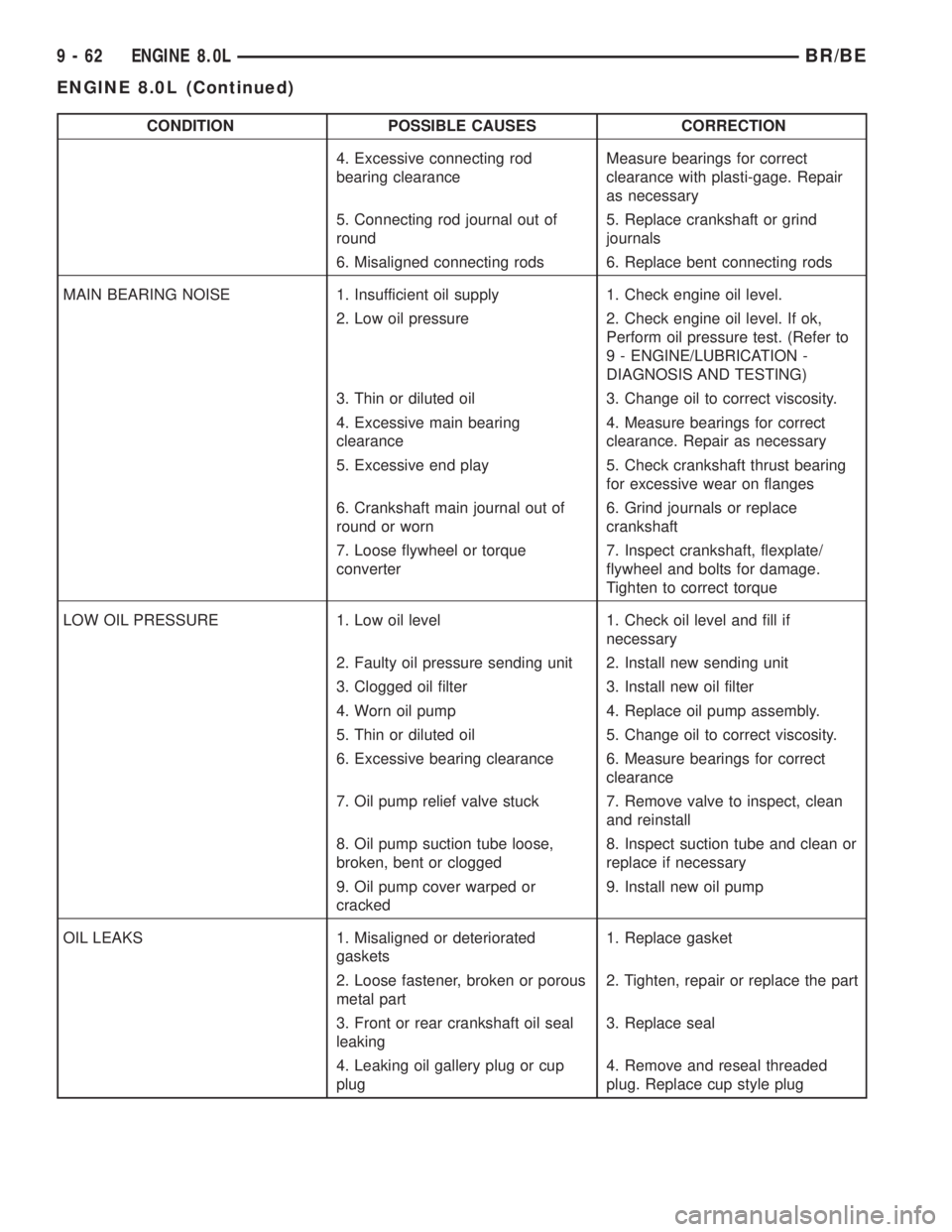
CONDITION POSSIBLE CAUSES CORRECTION
4. Excessive connecting rod
bearing clearanceMeasure bearings for correct
clearance with plasti-gage. Repair
as necessary
5. Connecting rod journal out of
round5. Replace crankshaft or grind
journals
6. Misaligned connecting rods 6. Replace bent connecting rods
MAIN BEARING NOISE 1. Insufficient oil supply 1. Check engine oil level.
2. Low oil pressure 2. Check engine oil level. If ok,
Perform oil pressure test. (Refer to
9 - ENGINE/LUBRICATION -
DIAGNOSIS AND TESTING)
3. Thin or diluted oil 3. Change oil to correct viscosity.
4. Excessive main bearing
clearance4. Measure bearings for correct
clearance. Repair as necessary
5. Excessive end play 5. Check crankshaft thrust bearing
for excessive wear on flanges
6. Crankshaft main journal out of
round or worn6. Grind journals or replace
crankshaft
7. Loose flywheel or torque
converter7. Inspect crankshaft, flexplate/
flywheel and bolts for damage.
Tighten to correct torque
LOW OIL PRESSURE 1. Low oil level 1. Check oil level and fill if
necessary
2. Faulty oil pressure sending unit 2. Install new sending unit
3. Clogged oil filter 3. Install new oil filter
4. Worn oil pump 4. Replace oil pump assembly.
5. Thin or diluted oil 5. Change oil to correct viscosity.
6. Excessive bearing clearance 6. Measure bearings for correct
clearance
7. Oil pump relief valve stuck 7. Remove valve to inspect, clean
and reinstall
8. Oil pump suction tube loose,
broken, bent or clogged8. Inspect suction tube and clean or
replace if necessary
9. Oil pump cover warped or
cracked9. Install new oil pump
OIL LEAKS 1. Misaligned or deteriorated
gaskets1. Replace gasket
2. Loose fastener, broken or porous
metal part2. Tighten, repair or replace the part
3. Front or rear crankshaft oil seal
leaking3. Replace seal
4. Leaking oil gallery plug or cup
plug4. Remove and reseal threaded
plug. Replace cup style plug
9 - 62 ENGINE 8.0LBR/BE
ENGINE 8.0L (Continued)
Page 1165 of 2255
INSTALLATIONÐFRONT OIL SEAL - FRONT
COVER REMOVED
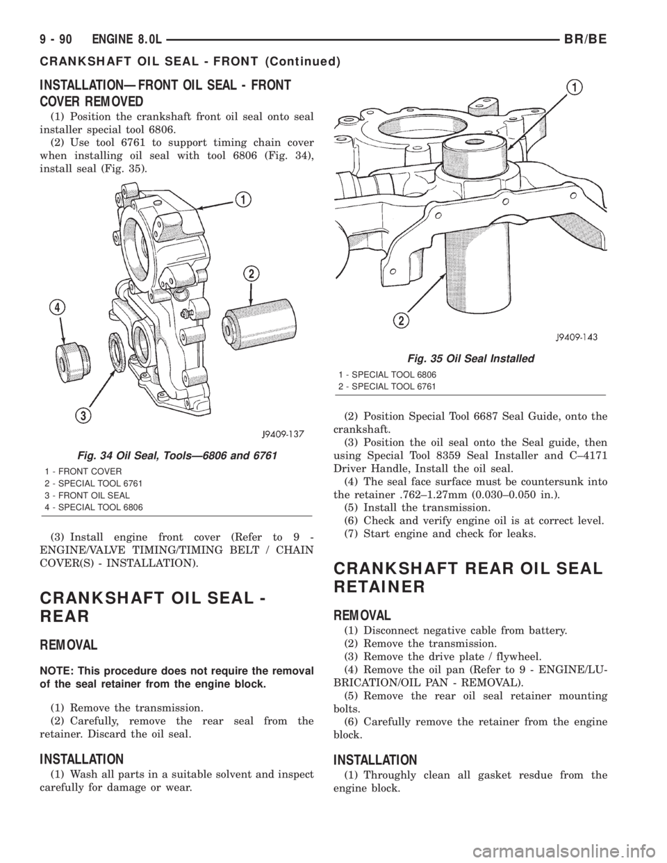
(1) Position the crankshaft front oil seal onto seal
installer special tool 6806.
(2) Use tool 6761 to support timing chain cover
when installing oil seal with tool 6806 (Fig. 34),
install seal (Fig. 35).
(3) Install engine front cover (Refer to 9 -
ENGINE/VALVE TIMING/TIMING BELT / CHAIN
COVER(S) - INSTALLATION).
CRANKSHAFT OIL SEAL -
REAR
REMOVAL
NOTE: This procedure does not require the removal
of the seal retainer from the engine block.
(1) Remove the transmission.
(2) Carefully, remove the rear seal from the
retainer. Discard the oil seal.
INSTALLATION
(1) Wash all parts in a suitable solvent and inspect
carefully for damage or wear.(2) Position Special Tool 6687 Seal Guide, onto the
crankshaft.
(3) Position the oil seal onto the Seal guide, then
using Special Tool 8359 Seal Installer and C±4171
Driver Handle, Install the oil seal.
(4) The seal face surface must be countersunk into
the retainer .762±1.27mm (0.030±0.050 in.).
(5) Install the transmission.
(6) Check and verify engine oil is at correct level.
(7) Start engine and check for leaks.
CRANKSHAFT REAR OIL SEAL
RETAINER
REMOVAL
(1) Disconnect negative cable from battery.
(2) Remove the transmission.
(3) Remove the drive plate / flywheel.
(4) Remove the oil pan (Refer to 9 - ENGINE/LU-
BRICATION/OIL PAN - REMOVAL).
(5) Remove the rear oil seal retainer mounting
bolts.
(6) Carefully remove the retainer from the engine
block.
INSTALLATION
(1) Throughly clean all gasket resdue from the
engine block.
Fig. 34 Oil Seal, ToolsÐ6806 and 6761
1 - FRONT COVER
2 - SPECIAL TOOL 6761
3 - FRONT OIL SEAL
4 - SPECIAL TOOL 6806
Fig. 35 Oil Seal Installed
1 - SPECIAL TOOL 6806
2 - SPECIAL TOOL 6761
9 - 90 ENGINE 8.0LBR/BE
CRANKSHAFT OIL SEAL - FRONT (Continued)
Page 1166 of 2255
(2) Use extream care and clean all gasket resdue
from the retainer.
(3) Apply a small amount of MopartSilicone Rub-
ber Adhesive Sealant to the retainer gasket. Position
the gasket onto the retainer.
(4) Position Special Tool 6687 Seal Guide onto the
crankshaft.
(5) Position the retainer and seal over the guide
and onto the engine block.
(6) Install the retainer mounting bolts. Tighten the
bolts to 22 N´m (16 ft. lbs.).
(7) Install the oil pan (Refer to 9 - ENGINE/LU-
BRICATION/OIL PAN - INSTALLATION).
(8) Install the drive plate / flywheel.
(9) Install the transmission.
(10) Check and verify engine oil level.
(11) Start engine and check for leaks.
HYDRAULIC LIFTERS
DIAGNOSIS AND TESTINGÐHYDRAULIC
TAPPETS
Before disassembling any part of the engine to cor-
rect tappet noise, check the oil pressure. If vehicle
has no oil pressure gauge, install a reliable gauge at
the pressure sending-unit. The pressure should be
between 207-552 kPa (30-80 psi) at 3,000 RPM.
Check the oil level after the engine reaches normal
operating temperature. Allow 5 minutes to stabilize
oil level, check dipstick. The oil level in the pan
should never be above the FULL mark or below the
ADD OIL mark on dipstick. Either of these two con-
ditions could be responsible for noisy tappets.
OIL LEVEL
HIGH
If oil level is above the FULL mark, it is possible
for the connecting rods to dip into the oil. With the
engine running, this condition could create foam in
the oil pan. Foam in oil pan would be fed to the
hydraulic tappets by the oil pump causing them to
lose length and allow valves to seat noisily.
LOW
Low oil level may allow oil pump to take in air.
When air is fed to the tappets, they lose length,
which allows valves to seat noisily. Any leaks on
intake side of oil pump through which air can be
drawn will create the same tappet action. Check the
lubrication system from the intake strainer to the
pump cover, including the relief valve retainer cap.
When tappet noise is due to aeration, it may be
intermittent or constant, and usually more than one
tappet will be noisy. When oil level and leaks havebeen corrected, operate the engine at fast idle. Run
engine for a sufficient time to allow all of the air
inside the tappets to be bled out.
TAPPET NOISE DIAGNOSIS
(1) To determine source of tappet noise, operate
engine at idle with cylinder head covers removed.
(2) Feel each valve spring or rocker arm to detect
noisy tappet. The noisy tappet will cause the affected
spring and/or rocker arm to vibrate or feel rough in
operation.
NOTE: Worn valve guides or cocked springs are
sometimes mistaken for noisy tappets. If such is
the case, noise may be dampened by applying side
thrust on the valve spring. If noise is not apprecia-
bly reduced, it can be assumed the noise is in the
tappet. Inspect the rocker arm push rod sockets
and push rod ends for wear.
(3) Valve tappet noise ranges from light noise to a
heavy click. A light noise is usually caused by exces-
sive leak-down around the unit plunger, or by the
plunger partially sticking in the tappet body cylinder.
The tappet should be replaced. A heavy click is
caused by a tappet check valve not seating, or by for-
eign particles wedged between the plunger and the
tappet body. This will cause the plunger to stick in
the down position. This heavy click will be accompa-
nied by excessive clearance between the valve stem
and rocker arm as valve closes. In either case, tappet
assembly should be removed for inspection and clean-
ing.
(4) The valve train generates a noise very much
like a light tappet noise during normal operation.
Care must be taken to ensure that tappets are mak-
ing the noise. If more than one tappet seems to be
noisy, it's probably not the tappets.
LEAK-DOWN TEST
After cleaning and inspection, test each tappet for
specified leak-down rate tolerance to ensure zero-lash
operation (Fig. 36).
Swing the weighted arm of the hydraulic valve tap-
pet tester away from the ram of the Universal Leak-
Down Tester.
(1) Place a 7.925-7.950 mm (0.312-0.313 inch)
diameter ball bearing on the plunger cap of the tap-
pet.
(2) Lift the ram and position the tappet (with the
ball bearing) inside the tester cup.
(3) Lower the ram, then adjust the nose of the ram
until it contacts the ball bearing. DO NOT tighten
the hex nut on the ram.
(4) Fill the tester cup with hydraulic valve tappet
test oil until the tappet is completely submerged.
BR/BEENGINE 8.0L 9 - 91
CRANKSHAFT REAR OIL SEAL RETAINER (Continued)
Page 1193 of 2255
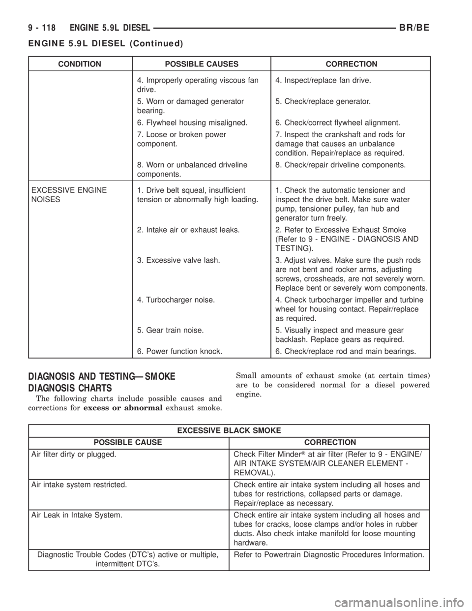
CONDITION POSSIBLE CAUSES CORRECTION
4. Improperly operating viscous fan
drive.4. Inspect/replace fan drive.
5. Worn or damaged generator
bearing.5. Check/replace generator.
6. Flywheel housing misaligned. 6. Check/correct flywheel alignment.
7. Loose or broken power
component.7. Inspect the crankshaft and rods for
damage that causes an unbalance
condition. Repair/replace as required.
8. Worn or unbalanced driveline
components.8. Check/repair driveline components.
EXCESSIVE ENGINE
NOISES1. Drive belt squeal, insufficient
tension or abnormally high loading.1. Check the automatic tensioner and
inspect the drive belt. Make sure water
pump, tensioner pulley, fan hub and
generator turn freely.
2. Intake air or exhaust leaks. 2. Refer to Excessive Exhaust Smoke
(Refer to 9 - ENGINE - DIAGNOSIS AND
TESTING).
3. Excessive valve lash. 3. Adjust valves. Make sure the push rods
are not bent and rocker arms, adjusting
screws, crossheads, are not severely worn.
Replace bent or severely worn components.
4. Turbocharger noise. 4. Check turbocharger impeller and turbine
wheel for housing contact. Repair/replace
as required.
5. Gear train noise. 5. Visually inspect and measure gear
backlash. Replace gears as required.
6. Power function knock. 6. Check/replace rod and main bearings.
DIAGNOSIS AND TESTINGÐSMOKE
DIAGNOSIS CHARTS
The following charts include possible causes and
corrections forexcess or abnormalexhaust smoke.Small amounts of exhaust smoke (at certain times)
are to be considered normal for a diesel powered
engine.
EXCESSIVE BLACK SMOKE
POSSIBLE CAUSE CORRECTION
Air filter dirty or plugged. Check Filter MinderTat air filter (Refer to 9 - ENGINE/
AIR INTAKE SYSTEM/AIR CLEANER ELEMENT -
REMOVAL).
Air intake system restricted. Check entire air intake system including all hoses and
tubes for restrictions, collapsed parts or damage.
Repair/replace as necessary.
Air Leak in Intake System. Check entire air intake system including all hoses and
tubes for cracks, loose clamps and/or holes in rubber
ducts. Also check intake manifold for loose mounting
hardware.
Diagnostic Trouble Codes (DTC's) active or multiple,
intermittent DTC's.Refer to Powertrain Diagnostic Procedures Information.
9 - 118 ENGINE 5.9L DIESELBR/BE
ENGINE 5.9L DIESEL (Continued)
Page 1194 of 2255
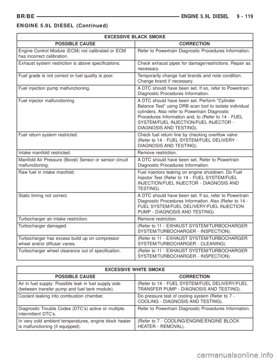
EXCESSIVE BLACK SMOKE
POSSIBLE CAUSE CORRECTION
Engine Control Module (ECM) not calibrated or ECM
has incorrect calibration.Refer to Powertrain Diagnostic Procedures Information.
Exhaust system restriction is above specifications. Check exhaust pipes for damage/restrictions. Repair as
necessary.
Fuel grade is not correct or fuel quality is poor. Temporarily change fuel brands and note condition.
Change brand if necessary.
Fuel injection pump malfunctioning. A DTC should have been set. If so, refer to Powertrain
Diagnostic Procedures Information.
Fuel injector malfunctioning. A DTC should have been set. Perform9Cylinder
Balance Test9using DRB scan tool to isolate individual
cylinders. Also refer to Powertrain Diagnostic
Procedures Information and, to (Refer to 14 - FUEL
SYSTEM/FUEL INJECTION/FUEL INJECTOR -
DIAGNOSIS AND TESTING).
Fuel return system restricted. Check fuel return line by checking overflow valve
(Refer to 14 - FUEL SYSTEM/FUEL DELIVERY -
DIAGNOSIS AND TESTING).
Intake manifold restricted. Remove restriction.
Manifold Air Pressure (Boost) Sensor or sensor circuit
malfunctioning.A DTC should have been set. Refer to Powertrain
Diagnostic Procedures Information.
Raw fuel in intake manifold. Fuel injectors leaking on engine shutdown. Do Fuel
Injector Test (Refer to 14 - FUEL SYSTEM/FUEL
INJECTION/FUEL INJECTOR - DIAGNOSIS AND
TESTING).
Static timing not correct. A DTC should have been set. If so, refer to Powertrain
Diagnostic Procedures Information. Also (Refer to 14 -
FUEL SYSTEM/FUEL DELIVERY/FUEL INJECTION
PUMP - DIAGNOSIS AND TESTING).
Turbocharger air intake restriction. Remove restriction.
Turbocharger damaged. (Refer to 11 - EXHAUST SYSTEM/TURBOCHARGER
SYSTEM/TURBOCHARGER - INSPECTION).
Turbocharger has excess build up on compressor
wheel and/or diffuser vanes.(Refer to 11 - EXHAUST SYSTEM/TURBOCHARGER
SYSTEM/TURBOCHARGER - CLEANING).
Turbocharger wheel clearance out of specification. (Refer to 11 - EXHAUST SYSTEM/TURBOCHARGER
SYSTEM/TURBOCHARGER - INSPECTION).
EXCESSIVE WHITE SMOKE
POSSIBLE CAUSE CORRECTION
Air in fuel supply: Possible leak in fuel supply side
(between transfer pump and fuel tank module).(Refer to 14 - FUEL SYSTEM/FUEL DELIVERY/FUEL
TRANSFER PUMP - DIAGNOSIS AND TESTING).
Coolant leaking into combustion chamber. Do pressure test of cooling system (Refer to 7 -
COOLING - DIAGNOSIS AND TESTING).
Diagnostic Trouble Codes (DTC's) active or multiple,
intermittent DTC's.Refer to Powertrain Diagnostic Procedures Information.
In very cold ambient temperatures, engine block heater
is malfunctioning (if equipped).(Refer to 7 - COOLING/ENGINE/ENGINE BLOCK
HEATER - REMOVAL).
BR/BEENGINE 5.9L DIESEL 9 - 119
ENGINE 5.9L DIESEL (Continued)
Page 1209 of 2255
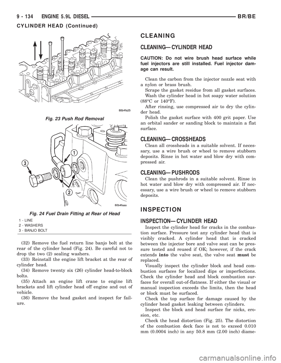
(32) Remove the fuel return line banjo bolt at the
rear of the cylinder head (Fig. 24). Be careful not to
drop the two (2) sealing washers.
(33) Reinstall the engine lift bracket at the rear of
cylinder head.
(34) Remove twenty six (26) cylinder head-to-block
bolts.
(35) Attach an engine lift crane to engine lift
brackets and lift cylinder head off engine and out of
vehicle.
(36) Remove the head gasket and inspect for fail-
ure.
CLEANING
CLEANINGÐCYLINDER HEAD
CAUTION: Do not wire brush head surface while
fuel injectors are still installed. Fuel injector dam-
age can result.
Clean the carbon from the injector nozzle seat with
a nylon or brass brush.
Scrape the gasket residue from all gasket surfaces.
Wash the cylinder head in hot soapy water solution
(88ÉC or 140ÉF).
After rinsing, use compressed air to dry the cylin-
der head.
Polish the gasket surface with 400 grit paper. Use
an orbital sander or sanding block to maintain a flat
surface.
CLEANINGÐCROSSHEADS
Clean all crossheads in a suitable solvent. If neces-
sary, use a wire brush or wheel to remove stubborn
deposits. Rinse in hot water and blow dry with com-
pressed air.
CLEANINGÐPUSHRODS
Clean the pushrods in a suitable solvent. Rinse in
hot water and blow dry with compressed air. If nec-
essary, use a wire brush or wheel to remove stubborn
deposits.
INSPECTION
INSPECTIONÐCYLINDER HEAD
Inspect the cylinder head for cracks in the combus-
tion surface. Pressure test any cylinder head that is
visibly cracked. A cylinder head that is cracked
between the injector bore and valve seat can be pres-
sure tested and reused if OK; however, if the crack
extendsintothe valve seat, the valve seatmustbe
replaced.
Visually inspect the cylinder block and head com-
bustion surfaces for localized dips or imperfections.
Check the cylinder head and block combustion sur-
faces for overall out-of-flatness. If either the visual or
manual inspection exceeds the limits, then the head
or block must be surfaced.
Check the top surface for damage caused by the
cylinder head gasket leaking between cylinders.
Inspect the block and head surface for nicks, ero-
sion, etc.
Check the head distortion (Fig. 25). The distortion
of the combustion deck face is not to exceed 0.010
mm (0.0004 inch) in any 50.8 mm (2.00 inch) diame-
Fig. 23 Push Rod Removal
Fig. 24 Fuel Drain Fitting at Rear of Head
1 - LINE
2 - WASHERS
3 - BANJO BOLT
9 - 134 ENGINE 5.9L DIESELBR/BE
CYLINDER HEAD (Continued)
Page 1221 of 2255
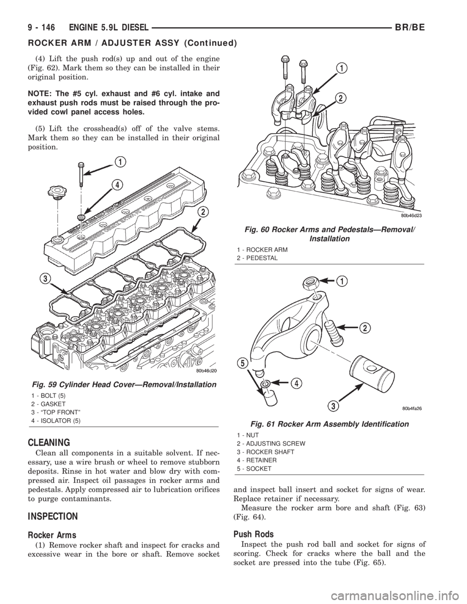
(4) Lift the push rod(s) up and out of the engine
(Fig. 62). Mark them so they can be installed in their
original position.
NOTE: The #5 cyl. exhaust and #6 cyl. intake and
exhaust push rods must be raised through the pro-
vided cowl panel access holes.
(5) Lift the crosshead(s) off of the valve stems.
Mark them so they can be installed in their original
position.
CLEANING
Clean all components in a suitable solvent. If nec-
essary, use a wire brush or wheel to remove stubborn
deposits. Rinse in hot water and blow dry with com-
pressed air. Inspect oil passages in rocker arms and
pedestals. Apply compressed air to lubrication orifices
to purge contaminants.
INSPECTION
Rocker Arms
(1) Remove rocker shaft and inspect for cracks and
excessive wear in the bore or shaft. Remove socketand inspect ball insert and socket for signs of wear.
Replace retainer if necessary.
Measure the rocker arm bore and shaft (Fig. 63)
(Fig. 64).
Push Rods
Inspect the push rod ball and socket for signs of
scoring. Check for cracks where the ball and the
socket are pressed into the tube (Fig. 65).
Fig. 59 Cylinder Head CoverÐRemoval/Installation
1 - BOLT (5)
2 - GASKET
3 - ªTOP FRONTº
4 - ISOLATOR (5)
Fig. 60 Rocker Arms and PedestalsÐRemoval/
Installation
1 - ROCKER ARM
2 - PEDESTAL
Fig. 61 Rocker Arm Assembly Identification
1 - NUT
2 - ADJUSTING SCREW
3 - ROCKER SHAFT
4 - RETAINER
5 - SOCKET
9 - 146 ENGINE 5.9L DIESELBR/BE
ROCKER ARM / ADJUSTER ASSY (Continued)
Page 1236 of 2255
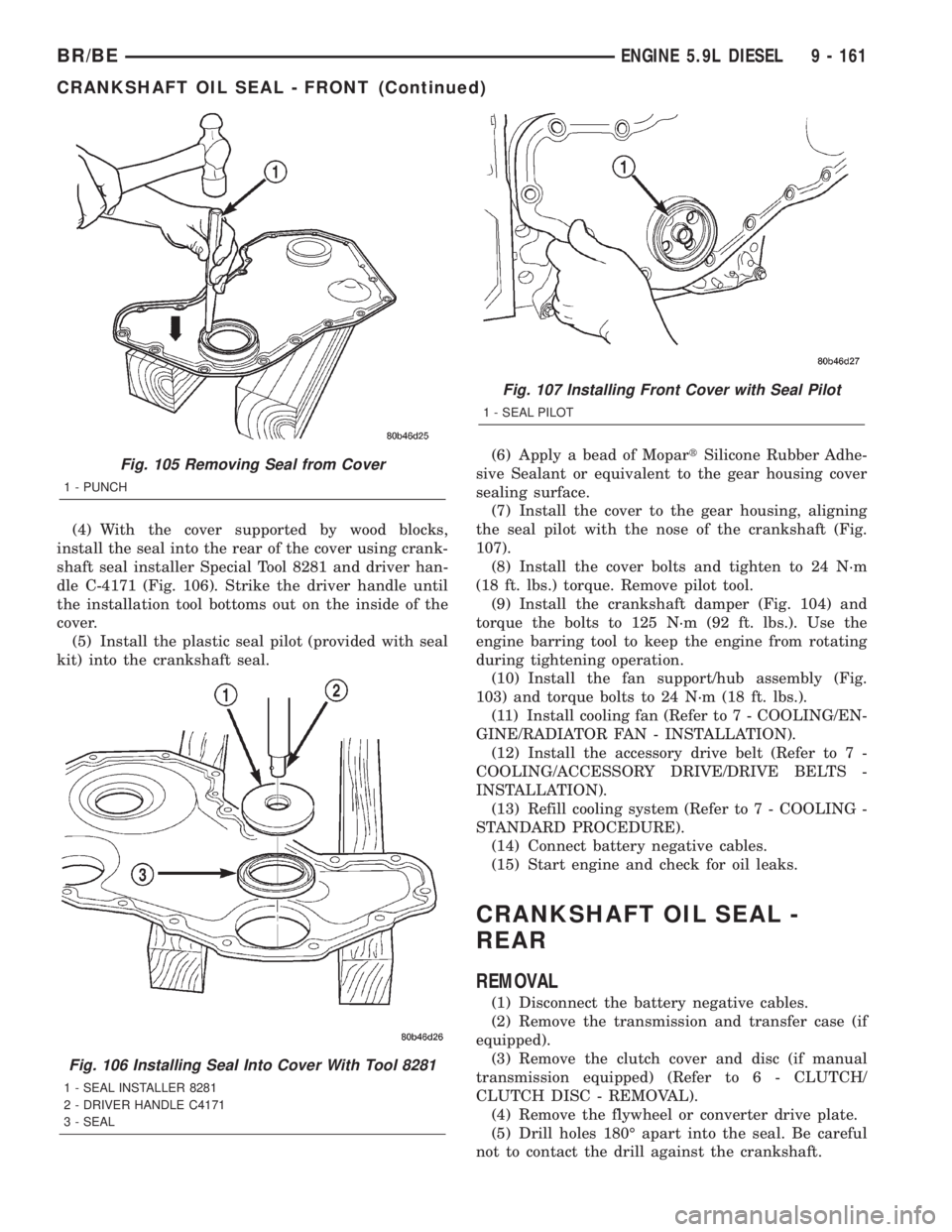
(4) With the cover supported by wood blocks,
install the seal into the rear of the cover using crank-
shaft seal installer Special Tool 8281 and driver han-
dle C-4171 (Fig. 106). Strike the driver handle until
the installation tool bottoms out on the inside of the
cover.
(5) Install the plastic seal pilot (provided with seal
kit) into the crankshaft seal.(6) Apply a bead of MopartSilicone Rubber Adhe-
sive Sealant or equivalent to the gear housing cover
sealing surface.
(7) Install the cover to the gear housing, aligning
the seal pilot with the nose of the crankshaft (Fig.
107).
(8) Install the cover bolts and tighten to 24 N´m
(18 ft. lbs.) torque. Remove pilot tool.
(9) Install the crankshaft damper (Fig. 104) and
torque the bolts to 125 N´m (92 ft. lbs.). Use the
engine barring tool to keep the engine from rotating
during tightening operation.
(10) Install the fan support/hub assembly (Fig.
103) and torque bolts to 24 N´m (18 ft. lbs.).
(11) Install cooling fan (Refer to 7 - COOLING/EN-
GINE/RADIATOR FAN - INSTALLATION).
(12) Install the accessory drive belt (Refer to 7 -
COOLING/ACCESSORY DRIVE/DRIVE BELTS -
INSTALLATION).
(13) Refill cooling system (Refer to 7 - COOLING -
STANDARD PROCEDURE).
(14) Connect battery negative cables.
(15) Start engine and check for oil leaks.
CRANKSHAFT OIL SEAL -
REAR
REMOVAL
(1) Disconnect the battery negative cables.
(2) Remove the transmission and transfer case (if
equipped).
(3) Remove the clutch cover and disc (if manual
transmission equipped) (Refer to 6 - CLUTCH/
CLUTCH DISC - REMOVAL).
(4) Remove the flywheel or converter drive plate.
(5) Drill holes 180É apart into the seal. Be careful
not to contact the drill against the crankshaft.
Fig. 105 Removing Seal from Cover
1 - PUNCH
Fig. 106 Installing Seal Into Cover With Tool 8281
1 - SEAL INSTALLER 8281
2 - DRIVER HANDLE C4171
3 - SEAL
Fig. 107 Installing Front Cover with Seal Pilot
1 - SEAL PILOT
BR/BEENGINE 5.9L DIESEL 9 - 161
CRANKSHAFT OIL SEAL - FRONT (Continued)