2002 DODGE RAM oil change
[x] Cancel search: oil changePage 1104 of 2255
INSTALLATIONÐCAMSHAFT
(1) Lubricate camshaft lobes and camshaft bearing
journals and insert the camshaft to within 51 mm (2
inches) of its final position in cylinder block.
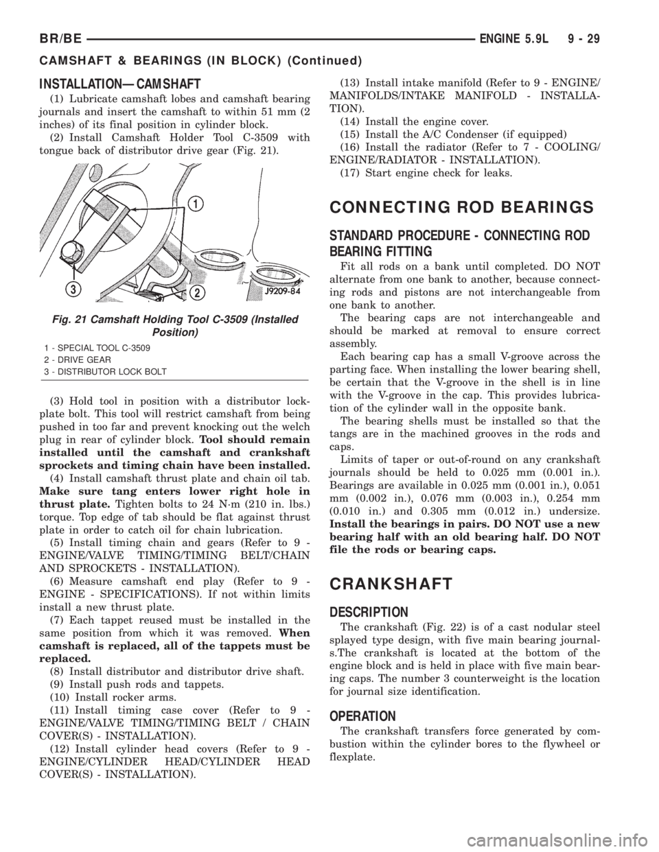
(2) Install Camshaft Holder Tool C-3509 with
tongue back of distributor drive gear (Fig. 21).
(3) Hold tool in position with a distributor lock-
plate bolt. This tool will restrict camshaft from being
pushed in too far and prevent knocking out the welch
plug in rear of cylinder block.Tool should remain
installed until the camshaft and crankshaft
sprockets and timing chain have been installed.
(4) Install camshaft thrust plate and chain oil tab.
Make sure tang enters lower right hole in
thrust plate.Tighten bolts to 24 N´m (210 in. lbs.)
torque. Top edge of tab should be flat against thrust
plate in order to catch oil for chain lubrication.
(5) Install timing chain and gears (Refer to 9 -
ENGINE/VALVE TIMING/TIMING BELT/CHAIN
AND SPROCKETS - INSTALLATION).
(6) Measure camshaft end play (Refer to 9 -
ENGINE - SPECIFICATIONS). If not within limits
install a new thrust plate.
(7) Each tappet reused must be installed in the
same position from which it was removed.When
camshaft is replaced, all of the tappets must be
replaced.
(8) Install distributor and distributor drive shaft.
(9) Install push rods and tappets.
(10) Install rocker arms.
(11) Install timing case cover (Refer to 9 -
ENGINE/VALVE TIMING/TIMING BELT / CHAIN
COVER(S) - INSTALLATION).
(12) Install cylinder head covers (Refer to 9 -
ENGINE/CYLINDER HEAD/CYLINDER HEAD
COVER(S) - INSTALLATION).(13) Install intake manifold (Refer to 9 - ENGINE/
MANIFOLDS/INTAKE MANIFOLD - INSTALLA-
TION).
(14) Install the engine cover.
(15) Install the A/C Condenser (if equipped)
(16) Install the radiator (Refer to 7 - COOLING/
ENGINE/RADIATOR - INSTALLATION).
(17) Start engine check for leaks.
CONNECTING ROD BEARINGS
STANDARD PROCEDURE - CONNECTING ROD
BEARING FITTING
Fit all rods on a bank until completed. DO NOT
alternate from one bank to another, because connect-
ing rods and pistons are not interchangeable from
one bank to another.
The bearing caps are not interchangeable and
should be marked at removal to ensure correct
assembly.
Each bearing cap has a small V-groove across the
parting face. When installing the lower bearing shell,
be certain that the V-groove in the shell is in line
with the V-groove in the cap. This provides lubrica-
tion of the cylinder wall in the opposite bank.
The bearing shells must be installed so that the
tangs are in the machined grooves in the rods and
caps.
Limits of taper or out-of-round on any crankshaft
journals should be held to 0.025 mm (0.001 in.).
Bearings are available in 0.025 mm (0.001 in.), 0.051
mm (0.002 in.), 0.076 mm (0.003 in.), 0.254 mm
(0.010 in.) and 0.305 mm (0.012 in.) undersize.
Install the bearings in pairs. DO NOT use a new
bearing half with an old bearing half. DO NOT
file the rods or bearing caps.
CRANKSHAFT
DESCRIPTION
The crankshaft (Fig. 22) is of a cast nodular steel
splayed type design, with five main bearing journal-
s.The crankshaft is located at the bottom of the
engine block and is held in place with five main bear-
ing caps. The number 3 counterweight is the location
for journal size identification.
OPERATION
The crankshaft transfers force generated by com-
bustion within the cylinder bores to the flywheel or
flexplate.
Fig. 21 Camshaft Holding Tool C-3509 (Installed
Position)
1 - SPECIAL TOOL C-3509
2 - DRIVE GEAR
3 - DISTRIBUTOR LOCK BOLT
BR/BEENGINE 5.9L 9 - 29
CAMSHAFT & BEARINGS (IN BLOCK) (Continued)
Page 1106 of 2255
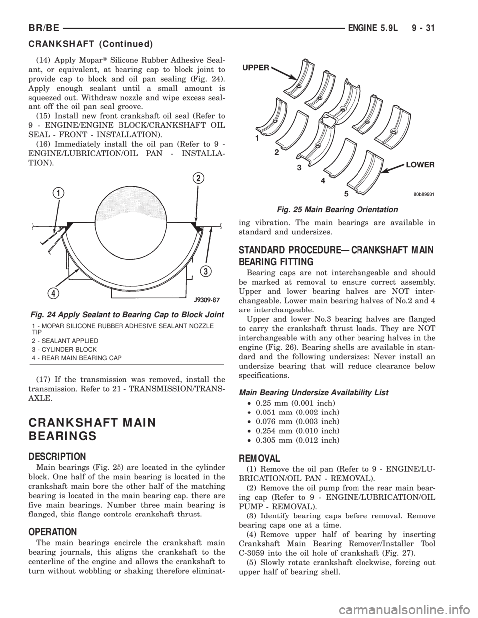
(14) Apply MopartSilicone Rubber Adhesive Seal-
ant, or equivalent, at bearing cap to block joint to
provide cap to block and oil pan sealing (Fig. 24).
Apply enough sealant until a small amount is
squeezed out. Withdraw nozzle and wipe excess seal-
ant off the oil pan seal groove.
(15) Install new front crankshaft oil seal (Refer to
9 - ENGINE/ENGINE BLOCK/CRANKSHAFT OIL
SEAL - FRONT - INSTALLATION).
(16) Immediately install the oil pan (Refer to 9 -
ENGINE/LUBRICATION/OIL PAN - INSTALLA-
TION).
(17) If the transmission was removed, install the
transmission. Refer to 21 - TRANSMISSION/TRANS-
AXLE.
CRANKSHAFT MAIN
BEARINGS
DESCRIPTION
Main bearings (Fig. 25) are located in the cylinder
block. One half of the main bearing is located in the
crankshaft main bore the other half of the matching
bearing is located in the main bearing cap. there are
five main bearings. Number three main bearing is
flanged, this flange controls crankshaft thrust.
OPERATION
The main bearings encircle the crankshaft main
bearing journals, this aligns the crankshaft to the
centerline of the engine and allows the crankshaft to
turn without wobbling or shaking therefore eliminat-ing vibration. The main bearings are available in
standard and undersizes.
STANDARD PROCEDUREÐCRANKSHAFT MAIN
BEARING FITTING
Bearing caps are not interchangeable and should
be marked at removal to ensure correct assembly.
Upper and lower bearing halves are NOT inter-
changeable. Lower main bearing halves of No.2 and 4
are interchangeable.
Upper and lower No.3 bearing halves are flanged
to carry the crankshaft thrust loads. They are NOT
interchangeable with any other bearing halves in the
engine (Fig. 26). Bearing shells are available in stan-
dard and the following undersizes: Never install an
undersize bearing that will reduce clearance below
specifications.
Main Bearing Undersize Availability List
²0.25 mm (0.001 inch)
²0.051 mm (0.002 inch)
²0.076 mm (0.003 inch)
²0.254 mm (0.010 inch)
²0.305 mm (0.012 inch)
REMOVAL
(1) Remove the oil pan (Refer to 9 - ENGINE/LU-
BRICATION/OIL PAN - REMOVAL).
(2) Remove the oil pump from the rear main bear-
ing cap (Refer to 9 - ENGINE/LUBRICATION/OIL
PUMP - REMOVAL).
(3) Identify bearing caps before removal. Remove
bearing caps one at a time.
(4) Remove upper half of bearing by inserting
Crankshaft Main Bearing Remover/Installer Tool
C-3059 into the oil hole of crankshaft (Fig. 27).
(5) Slowly rotate crankshaft clockwise, forcing out
upper half of bearing shell.
Fig. 24 Apply Sealant to Bearing Cap to Block Joint
1 - MOPAR SILICONE RUBBER ADHESIVE SEALANT NOZZLE
TIP
2 - SEALANT APPLIED
3 - CYLINDER BLOCK
4 - REAR MAIN BEARING CAP
Fig. 25 Main Bearing Orientation
BR/BEENGINE 5.9L 9 - 31
CRANKSHAFT (Continued)
Page 1114 of 2255
(6) Pistons and connecting rods must be removed
from top of cylinder block. When removing the
assemblies from the engine, rotate crankshaft so that
the connecting rod is centered in cylinder bore and at
BDC.Be careful not to nick crankshaft journals.
(7) After removal, install bearing cap on the mat-
ing rod.
CLEANING
Clean the piston and connecting rod assembly
using a suitable solvent.
INSPECTION
Check the connecting rod journal for excessive
wear, taper and scoring (Refer to 9 - ENGINE/EN-
GINE BLOCK/CONNECTING ROD BEARINGS -
STANDARD PROCEDURE).
Check the connecting rod for signs of twist or bend-
ing.
Check the piston for taper and elliptical shape
before it is fitted into the cylinder bore (Refer to 9 -
ENGINE/ENGINE BLOCK/PISTON & CONNECT-
ING ROD - STANDARD PROCEDURE).
Check the piston for scoring, or scraping marks in
the piston skirts. Check the ring lands for cracks
and/or deterioration.
INSTALLATION
(1) Be sure that compression ring gaps are stag-
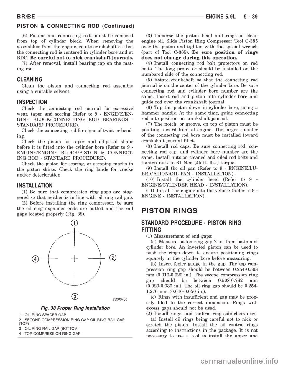
gered so that neither is in line with oil ring rail gap.
(2) Before installing the ring compressor, be sure
the oil ring expander ends are butted and the rail
gaps located properly (Fig. 38).(3) Immerse the piston head and rings in clean
engine oil. Slide Piston Ring Compressor Tool C-385
over the piston and tighten with the special wrench
(part of Tool C-385).Be sure position of rings
does not change during this operation.
(4) Install connecting rod bolt protectors on rod
bolts. The long protector should be installed on the
numbered side of the connecting rod.
(5) Rotate crankshaft so that the connecting rod
journal is on the center of the cylinder bore. Be sure
connecting rod and cylinder bore number are the
same. Insert rod and piston into cylinder bore and
guide rod over the crankshaft journal.
(6) Tap the piston down in cylinder bore, using a
hammer handle. At the same time, guide connecting
rod into position on crankshaft journal.
(7) The notch, or groove, on top of piston must be
pointing toward front of engine. The larger chamfer
of the connecting rod bore must be installed toward
crankshaft journal fillet.
(8) Install rod caps. Be sure connecting rod, con-
necting rod cap, and cylinder bore number are the
same. Install nuts on cleaned and oiled rod bolts and
tighten nuts to 61 N´m (45 ft. lbs.) torque.
(9) Install the oil pan (Refer to 9 - ENGINE/LU-
BRICATION/OIL PAN - INSTALLATION).
(10) Install the cylinder head (Refer to 9 -
ENGINE/CYLINDER HEAD - INSTALLATION).
(11) Install the engine into the vehicle (Refer to 9 -
ENGINE - INSTALLATION).
PISTON RINGS
STANDARD PROCEDURE - PISTON RING
FITTING
(1) Measurement of end gaps:
(a) Measure piston ring gap 2 in. from bottom of
cylinder bore. An inverted piston can be used to
push the rings down to ensure positioning rings
squarely in the cylinder bore before measuring.
(b) Insert feeler gauge in the gap. The top com-
pression ring gap should be between 0.254-0.508
mm (0.010-0.020 in.). The second compression ring
gap should be between 0.508-0.762 mm
(0.020-0.030 in.). The oil ring gap should be 0.254-
1.270 mm (0.010-0.050 in.).
(c) Rings with insufficient end gap may be prop-
erly filed to the correct dimension. Rings with
excess gaps should not be used.
(2) Install rings, and confirm ring side clearance:
(a) Install oil rings being careful not to nick or
scratch the piston. Install the oil control rings
according to instructions in the package. It is not
necessary to use a tool to install the upper and
Fig. 38 Proper Ring Installation
1 - OIL RING SPACER GAP
2 - SECOND COMPRESSION RING GAP OIL RING RAIL GAP
(TOP)
3 - OIL RING RAIL GAP (BOTTOM)
4 - TOP COMPRESSION RING GAP
BR/BEENGINE 5.9L 9 - 39
PISTON & CONNECTING ROD (Continued)
Page 1120 of 2255
(4) If dye is not observed, drive the vehicle at var-
ious speeds for approximately 24km (15 miles), and
repeat previous step.
(5) If the oil leak source is not positively identified
at this time, proceed with the air leak detection test
method as follows:
(6) Disconnect the breather cap to air cleaner hose
at the breather cap end. Cap or plug breather cap
nipple.
(7) Remove the PCV valve from the cylinder head
cover. Cap or plug the PCV valve grommet.
(8) Attach an air hose with pressure gauge and
regulator to the dipstick tube.
CAUTION: Do not subject the engine assembly to
more than 20.6 kpa (3 PSI) of test pressure.
(9) Gradually apply air pressure from 1 psi to 2.5
psi maximum while applying soapy water at the sus-
pected source. Adjust the regulator to the suitable
test pressure that provide the best bubbles which
will pinpoint the leak source. If the oil leak is
detected and identified, repair per service manual
procedures.
(10) If the leakage occurs at the rear oil seal area,
refer to the section, Inspection for Rear Seal Area
Leak.
(11) If no leaks are detected, turn off the air sup-
ply and remove the air hose and all plugs and caps.
Install the PCV valve and breather cap hose. Proceed
to next step.
(12) Clean the oil off the suspect oil leak area
using a suitable solvent. Drive the vehicle at various
speeds approximately 24 km (15 miles). Inspect the
engine for signs of an oil leak by using a black light.
DIAGNOSIS AND TESTINGÐENGINE OIL
PRESSURE
(1) Remove oil pressure sending unit.
(2) Install Oil Pressure Line and Gauge Tool
C-3292. Start engine and record pressure. (Refer to 9
- ENGINE - SPECIFICATIONS).
OIL
STANDARD PROCEDURE - ENGINE OIL
OIL LEVEL INDICATOR (DIPSTICK)
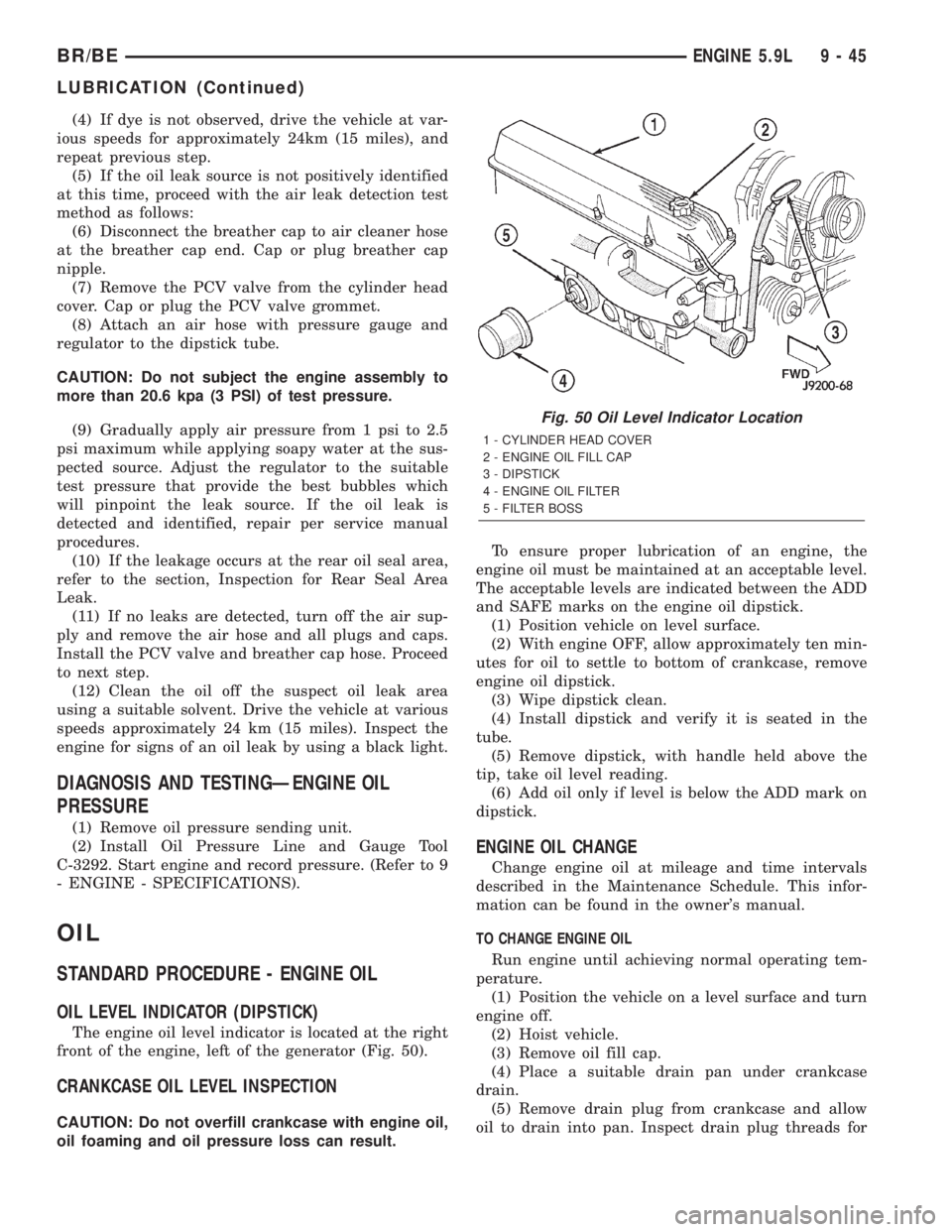
The engine oil level indicator is located at the right
front of the engine, left of the generator (Fig. 50).
CRANKCASE OIL LEVEL INSPECTION
CAUTION: Do not overfill crankcase with engine oil,
oil foaming and oil pressure loss can result.To ensure proper lubrication of an engine, the
engine oil must be maintained at an acceptable level.
The acceptable levels are indicated between the ADD
and SAFE marks on the engine oil dipstick.
(1) Position vehicle on level surface.
(2) With engine OFF, allow approximately ten min-
utes for oil to settle to bottom of crankcase, remove
engine oil dipstick.
(3) Wipe dipstick clean.
(4) Install dipstick and verify it is seated in the
tube.
(5) Remove dipstick, with handle held above the
tip, take oil level reading.
(6) Add oil only if level is below the ADD mark on
dipstick.
ENGINE OIL CHANGE
Change engine oil at mileage and time intervals
described in the Maintenance Schedule. This infor-
mation can be found in the owner's manual.
TO CHANGE ENGINE OIL
Run engine until achieving normal operating tem-
perature.
(1) Position the vehicle on a level surface and turn
engine off.
(2) Hoist vehicle.
(3) Remove oil fill cap.
(4) Place a suitable drain pan under crankcase
drain.
(5) Remove drain plug from crankcase and allow
oil to drain into pan. Inspect drain plug threads for
Fig. 50 Oil Level Indicator Location
1 - CYLINDER HEAD COVER
2 - ENGINE OIL FILL CAP
3 - DIPSTICK
4 - ENGINE OIL FILTER
5 - FILTER BOSS
BR/BEENGINE 5.9L 9 - 45
LUBRICATION (Continued)
Page 1121 of 2255
stretching or other damage. Replace drain plug and
gasket if damaged.
(6) Install drain plug in crankcase.
(7) Change oil filter (Refer to 9 - ENGINE/LUBRI-
CATION/OIL FILTER - REMOVAL).
(8) Lower vehicle and fill crankcase with specified
type (Refer to LUBRICATION & MAINTENANCE/
FLUID TYPES - DESCRIPTION) and amount of
engine oil (Refer to LUBRICATION & MAINTE-
NANCE - SPECIFICATIONS).
(9) Install oil fill cap.
(10) Start engine and inspect for leaks.
(11) Stop engine and inspect oil level.
OIL FILTER
REMOVAL
All engines are equipped with a high quality full-
flow, disposable type oil filter. DaimlerChrysler Cor-
poration recommends a Mopartor equivalent oil
filter be used.
(1) Position a drain pan under the oil filter.
(2) Using a suitable oil filter wrench loosen filter.
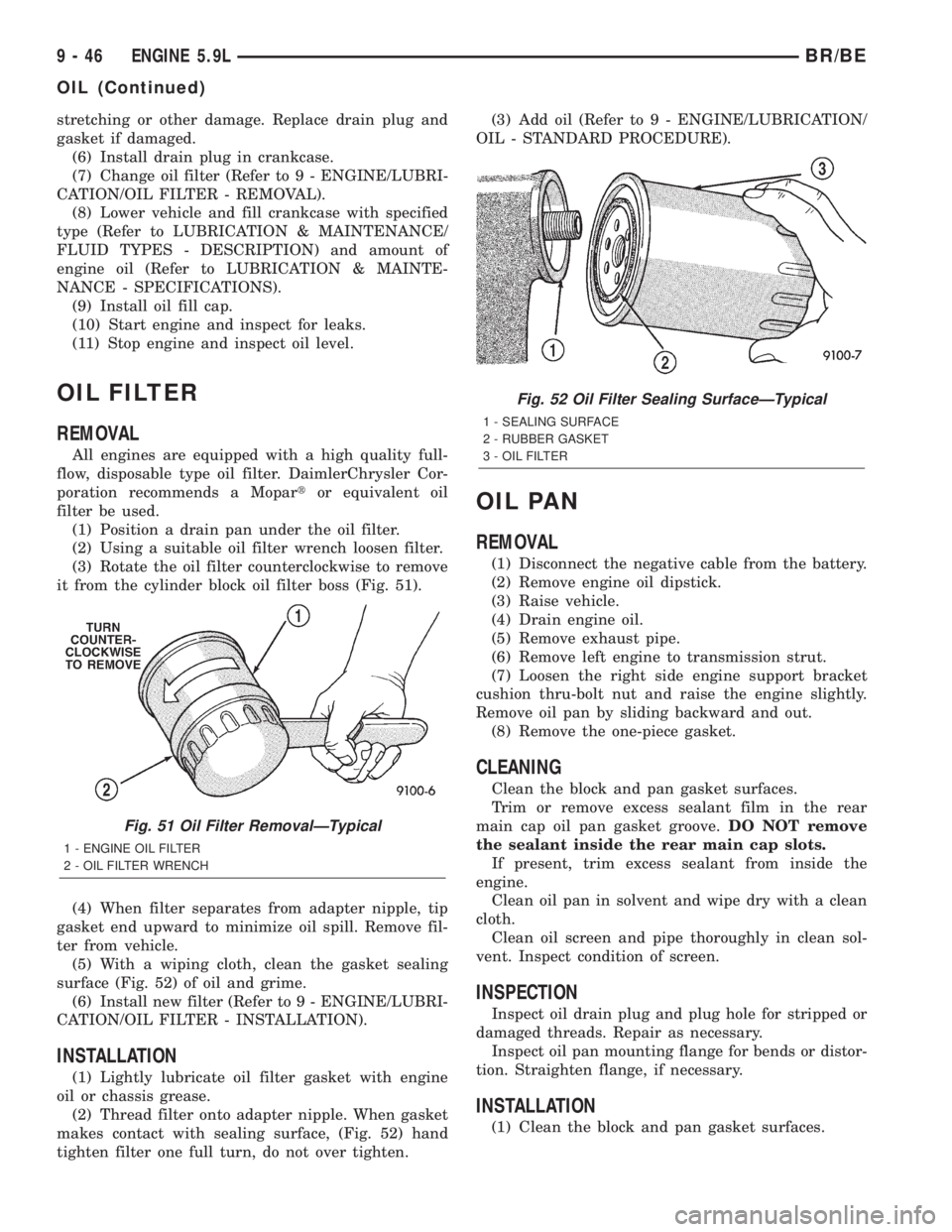
(3) Rotate the oil filter counterclockwise to remove
it from the cylinder block oil filter boss (Fig. 51).
(4) When filter separates from adapter nipple, tip
gasket end upward to minimize oil spill. Remove fil-
ter from vehicle.
(5) With a wiping cloth, clean the gasket sealing
surface (Fig. 52) of oil and grime.
(6) Install new filter (Refer to 9 - ENGINE/LUBRI-
CATION/OIL FILTER - INSTALLATION).
INSTALLATION
(1) Lightly lubricate oil filter gasket with engine
oil or chassis grease.
(2) Thread filter onto adapter nipple. When gasket
makes contact with sealing surface, (Fig. 52) hand
tighten filter one full turn, do not over tighten.(3) Add oil (Refer to 9 - ENGINE/LUBRICATION/
OIL - STANDARD PROCEDURE).
OIL PAN
REMOVAL
(1) Disconnect the negative cable from the battery.
(2) Remove engine oil dipstick.
(3) Raise vehicle.
(4) Drain engine oil.
(5) Remove exhaust pipe.
(6) Remove left engine to transmission strut.
(7) Loosen the right side engine support bracket
cushion thru-bolt nut and raise the engine slightly.
Remove oil pan by sliding backward and out.
(8) Remove the one-piece gasket.
CLEANING
Clean the block and pan gasket surfaces.
Trim or remove excess sealant film in the rear
main cap oil pan gasket groove.DO NOT remove
the sealant inside the rear main cap slots.
If present, trim excess sealant from inside the
engine.
Clean oil pan in solvent and wipe dry with a clean
cloth.
Clean oil screen and pipe thoroughly in clean sol-
vent. Inspect condition of screen.
INSPECTION
Inspect oil drain plug and plug hole for stripped or
damaged threads. Repair as necessary.
Inspect oil pan mounting flange for bends or distor-
tion. Straighten flange, if necessary.
INSTALLATION
(1) Clean the block and pan gasket surfaces.
Fig. 51 Oil Filter RemovalÐTypical
1 - ENGINE OIL FILTER
2 - OIL FILTER WRENCH
Fig. 52 Oil Filter Sealing SurfaceÐTypical
1 - SEALING SURFACE
2 - RUBBER GASKET
3 - OIL FILTER
9 - 46 ENGINE 5.9LBR/BE
OIL (Continued)
Page 1125 of 2255
(2) Position the oil pump cover onto the pump
body. Tighten cover bolts to 11 N´m (95 in. lbs.)
torque.
(3) Install the relief valve and spring. Insert the
cotter pin.
(4) Tap on a new retainer cap.
(5) Prime oil pump before installation by filling
rotor cavity with engine oil.
INSTALLATION
(1) Install oil pump. During installation slowly
rotate pump body to ensure driveshaft-to-pump rotor
shaft engagement.
(2) Hold the oil pump base flush against mating
surface on No.5 main bearing cap. Finger tighten
pump attaching bolts. Tighten attaching bolts to 41
N´m (30 ft. lbs.) torque.
(3) Install the oil pan (Refer to 9 - ENGINE/LU-
BRICATION/OIL PAN - INSTALLATION).
INTAKE MANIFOLD
DESCRIPTION
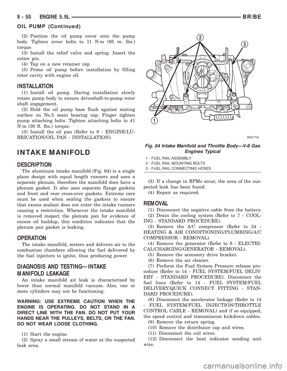
The aluminum intake manifold (Fig. 64) is a single
plane design with equal length runners and uses a
separate plenum, therefore the manifold does have a
plenum gasket. It also uses separate flange gaskets
and front and rear cross-over gaskets. Extreme care
must be used when sealing the gaskets to ensure
that excess sealant does not enter the intake runners
causing a restriction. Whenever the intake manifold
is removed inspect the plenum pan for evidence of
excess oil buildup, this condition indicates that the
plenum pan gasket is leaking.
OPERATION
The intake manifold, meters and delivers air to the
combustion chambers allowing the fuel delivered by
the fuel injectors to ignite, thus producing power.
DIAGNOSIS AND TESTINGÐINTAKE
MANIFOLD LEAKAGE
An intake manifold air leak is characterized by
lower than normal manifold vacuum. Also, one or
more cylinders may not be functioning.
WARNING: USE EXTREME CAUTION WHEN THE
ENGINE IS OPERATING. DO NOT STAND IN A
DIRECT LINE WITH THE FAN. DO NOT PUT YOUR
HANDS NEAR THE PULLEYS, BELTS, OR THE FAN.
DO NOT WEAR LOOSE CLOTHING.
(1) Start the engine.
(2) Spray a small stream of water at the suspected
leak area.(3) If a change in RPMs occur, the area of the sus-
pected leak has been found.
(4) Repair as required.
REMOVAL
(1) Disconnect the negative cable from the battery.
(2) Drain the cooling system (Refer to 7 - COOL-
ING - STANDARD PROCEDURE).
(3) Remove the A/C compressor (Refer to 24 -
HEATING & AIR CONDITIONING/PLUMBING/A/C
COMPRESSOR - REMOVAL).
(4) Remove the generator (Refer to 8 - ELECTRI-
CAL/CHARGING/GENERATOR - REMOVAL).
(5) Remove the accessory drive bracket.
(6) Remove the air cleaner.
(7) Perform the Fuel System Pressure release pro-
cedure (Refer to 14 - FUEL SYSTEM/FUEL DELIV-
ERY - STANDARD PROCEDURE). Disconnect the
fuel lines (Refer to 14 - FUEL SYSTEM/FUEL
DELIVERY/QUICK CONNECT FITTING - STAN-
DARD PROCEDURE).
(8) Disconnect the accelerator linkage (Refer to 14
- FUEL SYSTEM/FUEL INJECTION/THROTTLE
CONTROL CABLE - REMOVAL) and if so equipped,
the speed control and transmission kickdown cables.
(9) Remove the return spring.
(10) Remove the distributor cap and wires.
(11) Disconnect the coil wires.
(12) Disconnect the heat indicator sending unit
wire.
Fig. 64 Intake Manifold and Throttle BodyÐV-8 Gas
Engines Typical
1 - FUEL RAIL ASSEMBLY
2 - FUEL RAIL MOUNTING BOLTS
3 - FUEL RAIL CONNECTING HOSES
9 - 50 ENGINE 5.9LBR/BE
OIL PUMP (Continued)
Page 1136 of 2255
CONDITION POSSIBLE CAUSES CORRECTION
3. Dirt in fuel system 3. Clean fuel system
4. Burned, warped or pitted valves 4. Install new valves
5. Faulty coil 5. Test and replace as necessary
(Refer to 8 - ELECTRICAL/
IGNITION CONTROL/IGNITION
COIL - REMOVAL)
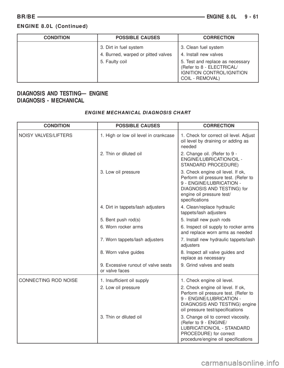
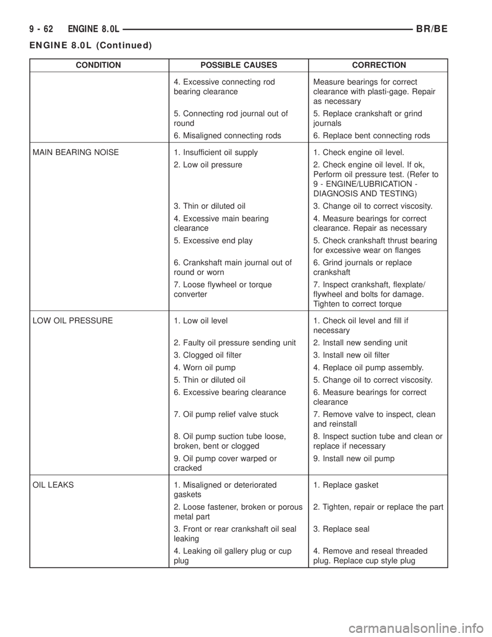
DIAGNOSIS AND TESTINGÐ ENGINE
DIAGNOSIS - MECHANICAL
ENGINE MECHANICAL DIAGNOSIS CHART
CONDITION POSSIBLE CAUSES CORRECTION
NOISY VALVES/LIFTERS 1. High or low oil level in crankcase 1. Check for correct oil level. Adjust
oil level by draining or adding as
needed
2. Thin or diluted oil 2. Change oil. (Refer to 9 -
ENGINE/LUBRICATION/OIL -
STANDARD PROCEDURE)
3. Low oil pressure 3. Check engine oil level. If ok,
Perform oil pressure test. (Refer to
9 - ENGINE/LUBRICATION -
DIAGNOSIS AND TESTING) for
engine oil pressure test/
specifications
4. Dirt in tappets/lash adjusters 4. Clean/replace hydraulic
tappets/lash adjusters
5. Bent push rod(s) 5. Install new push rods
6. Worn rocker arms 6. Inspect oil supply to rocker arms
and replace worn arms as needed
7. Worn tappets/lash adjusters 7. Install new hydraulic tappets/lash
adjusters
8. Worn valve guides 8. Inspect all valve guides and
replace as necessary
9. Excessive runout of valve seats
or valve faces9. Grind valves and seats
CONNECTING ROD NOISE 1. Insufficient oil supply 1. Check engine oil level.
2. Low oil pressure 2. Check engine oil level. If ok,
Perform oil pressure test. (Refer to
9 - ENGINE/LUBRICATION -
DIAGNOSIS AND TESTING) engine
oil pressure test/specifications
3. Thin or diluted oil 3. Change oil to correct viscosity.
(Refer to 9 - ENGINE/
LUBRICATION/OIL - STANDARD
PROCEDURE) for correct
procedure/engine oil specifications
BR/BEENGINE 8.0L 9 - 61
ENGINE 8.0L (Continued)
Page 1137 of 2255
CONDITION POSSIBLE CAUSES CORRECTION
4. Excessive connecting rod
bearing clearanceMeasure bearings for correct
clearance with plasti-gage. Repair
as necessary
5. Connecting rod journal out of
round5. Replace crankshaft or grind
journals
6. Misaligned connecting rods 6. Replace bent connecting rods
MAIN BEARING NOISE 1. Insufficient oil supply 1. Check engine oil level.
2. Low oil pressure 2. Check engine oil level. If ok,
Perform oil pressure test. (Refer to
9 - ENGINE/LUBRICATION -
DIAGNOSIS AND TESTING)
3. Thin or diluted oil 3. Change oil to correct viscosity.
4. Excessive main bearing
clearance4. Measure bearings for correct
clearance. Repair as necessary
5. Excessive end play 5. Check crankshaft thrust bearing
for excessive wear on flanges
6. Crankshaft main journal out of
round or worn6. Grind journals or replace
crankshaft
7. Loose flywheel or torque
converter7. Inspect crankshaft, flexplate/
flywheel and bolts for damage.
Tighten to correct torque
LOW OIL PRESSURE 1. Low oil level 1. Check oil level and fill if
necessary
2. Faulty oil pressure sending unit 2. Install new sending unit
3. Clogged oil filter 3. Install new oil filter
4. Worn oil pump 4. Replace oil pump assembly.
5. Thin or diluted oil 5. Change oil to correct viscosity.
6. Excessive bearing clearance 6. Measure bearings for correct
clearance
7. Oil pump relief valve stuck 7. Remove valve to inspect, clean
and reinstall
8. Oil pump suction tube loose,
broken, bent or clogged8. Inspect suction tube and clean or
replace if necessary
9. Oil pump cover warped or
cracked9. Install new oil pump
OIL LEAKS 1. Misaligned or deteriorated
gaskets1. Replace gasket
2. Loose fastener, broken or porous
metal part2. Tighten, repair or replace the part
3. Front or rear crankshaft oil seal
leaking3. Replace seal
4. Leaking oil gallery plug or cup
plug4. Remove and reseal threaded
plug. Replace cup style plug
9 - 62 ENGINE 8.0LBR/BE
ENGINE 8.0L (Continued)