2002 DODGE RAM center console
[x] Cancel search: center consolePage 878 of 2255

8W-50 FRONT LIGHTING
Component Page
Cargo Lamp No. 1.................... 8W-50-2
Cargo Lamp No. 2.................... 8W-50-2
Center Identification Lamp............. 8W-50-8
Central Timer Module................. 8W-50-2
Daytime Running Lamp Module.... 8W-50-6, 9, 11,
12, 13
Fog Lamp Relay............. 8W-50-6, 10, 11, 12
Fuse 5 (JB)......................... 8W-50-3
Fuse 7 (JB)........................ 8W-50-12
Fuse 14 (JB)...................... 8W-50-6, 9
Fuse B (PDC)....................... 8W-50-4
Fuse C (PDC)....................... 8W-50-4
Fuse E (PDC)....................... 8W-50-5
Fuse F (PDC).................. 8W-50-3, 10, 11
Fuse G (PDC)................ 8W-50-10, 11, 12
G100........................... 8W-50-7, 12
G102........................... 8W-50-5, 13
G201.................. 8W-50-2, 4, 6, 9, 10, 11
G302.............................. 8W-50-8
Headlamp Beam Select Switch...... 8W-50-4, 6, 9,
10, 13
Headlamp Switch........... 8W-50-2, 3, 4, 10, 11
Ignition Switch...................... 8W-50-3
Instrument Cluster............ 8W-50-2, 6, 9, 13Component Page
Joint Connector No. 1............ 8W-50-4, 5, 13
Joint Connector No. 5........... 8W-50-3, 10, 11
Joint Connector No. 6............... 8W-50-2, 3
Joint Connector No. 8............... 8W-50-2, 3
Junction Block.......... 8W-50-2, 3, 6, 7, 8, 9, 12
Left Fog Lamp................... 8W-50-10, 11
Left Headlamp...................... 8W-50-5
Left Outboard Clearance Lamp.......... 8W-50-8
Left Outboard Headlamp............ 8W-50-4, 6
Left Outboard Identification Lamp....... 8W-50-8
Left Park/Turn Signal Lamp............ 8W-50-7
Overhead Console.................... 8W-50-2
Park Brake Switch.................. 8W-50-12
Power Distribution Center...... 8W-50-3, 4, 5, 10,
11 , 1 2
Quad High Beam Relay........... 8W-50-5, 6, 13
Right Fog Lamp................. 8W-50-10, 11
Right Headlamp..................... 8W-50-5
Right Outboard Clearance Lamp........ 8W-50-8
Right Outboard Headlamp........... 8W-50-4, 6
Right Outboard Identification Lamp...... 8W-50-8
Right Park/Turn Signal Lamp........... 8W-50-7
Security Relay...................... 8W-50-13
Trailer Tow Relay.................... 8W-50-7
BR/BE8W-50 FRONT LIGHTING 8W - 50 - 1
Page 1026 of 2255
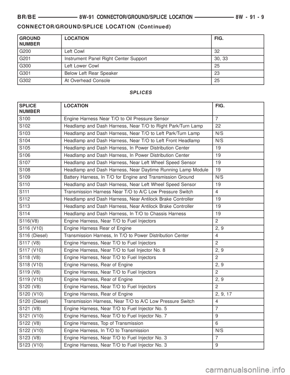
GROUND
NUMBERLOCATION FIG.
G200 Left Cowl 32
G201 Instrument Panel Right Center Support 30, 33
G300 Left Lower Cowl 25
G301 Below Left Rear Speaker 23
G302 At Overhead Console 25
SPLICES
SPLICE
NUMBERLOCATION FIG.
S100 Engine Harness Near T/O to Oil Pressure Sensor 7
S102 Headlamp and Dash Harness, Near T/O to Right Park/Turn Lamp 22
S103 Headlamp and Dash Harness, Near T/O to Left Park/Turn Lamp N/S
S104 Headlamp and Dash Harness, Near T/O to Left Front Headlamp N/S
S105 Headlamp and Dash Harness, In Power Distribution Center 19
S106 Headlamp and Dash Harness, In Power Distribution Center 19
S107 Headlamp and Dash Harness, Near Left Wheel Speed Sensor 19
S108 Headlamp and Dash Harness, Near Daytime Running Lamp Module 19
S109 Battery Harness, In T/O for Engine and Transmission Ground N/S
S110 Headlamp and Dash Harness, Near Left Wheel Speed Sensor 19
S111 Transmission Harness Near T/O to A/C Low Pressure Switch 4
S112 Headlamp and Dash Harness, Near Antilock Brake Controller 19
S113 Headlamp and Dash Harness, Near Antilock Brake Controller 19
S114 Headlamp and Dash Harness, In T/O to Chassis Harness 19
S116(V8) Engine Harness, Near T/O to Fuel Injectors 2
S116 (V10) Engine Harness Rear of Engine 2, 9
S116 (Diesel) Transmission Harness, In T/O to Power Distribution Center 4
S117 (V8) Engine Harness, Near T/O to Fuel Injectors 2
S117 (V10) Engine Harness, Near T/O to fuel Injector No. 8 2, 9
S118 (V8) Engine Harness, Near T/O to Fuel Injectors 2
S118 (V10) Engine Harness, Rear of Engine 2, 9
S119 (V8) Engine Harness, Near T/O to Fuel Injectors 2
S119 (V10) Engine Harness, Rear of Engine 2, 9
S120 (V8) Engine Harness, Near T/O to Fuel Injectors 2
S120 (V10) Engine Harness, Rear of Engine 2, 9, 17
S120 (Diesel) Transmission Harness, Near T/O to A/C Low Pressure Switch 4
S121 (V8) Engine Harness, Near T/O to Fuel Injector No. 5 7
S121 (V10) Engine Harness, Near T/O to Fuel Injector No. 7 9
S122 (V8) Engine Harness, Top of Transmission 6
S122 (V10) Engine Harness, In T/O to Transmission N/S
S123 (V8) Engine Harness, Near T/O to Fuel Injector No. 3 7
S123 (V10) Engine Harness, Near T/O to Fuel Injector No. 3 9
BR/BE8W-91 CONNECTOR/GROUND/SPLICE LOCATION 8W - 91 - 9
CONNECTOR/GROUND/SPLICE LOCATION (Continued)
Page 2028 of 2255
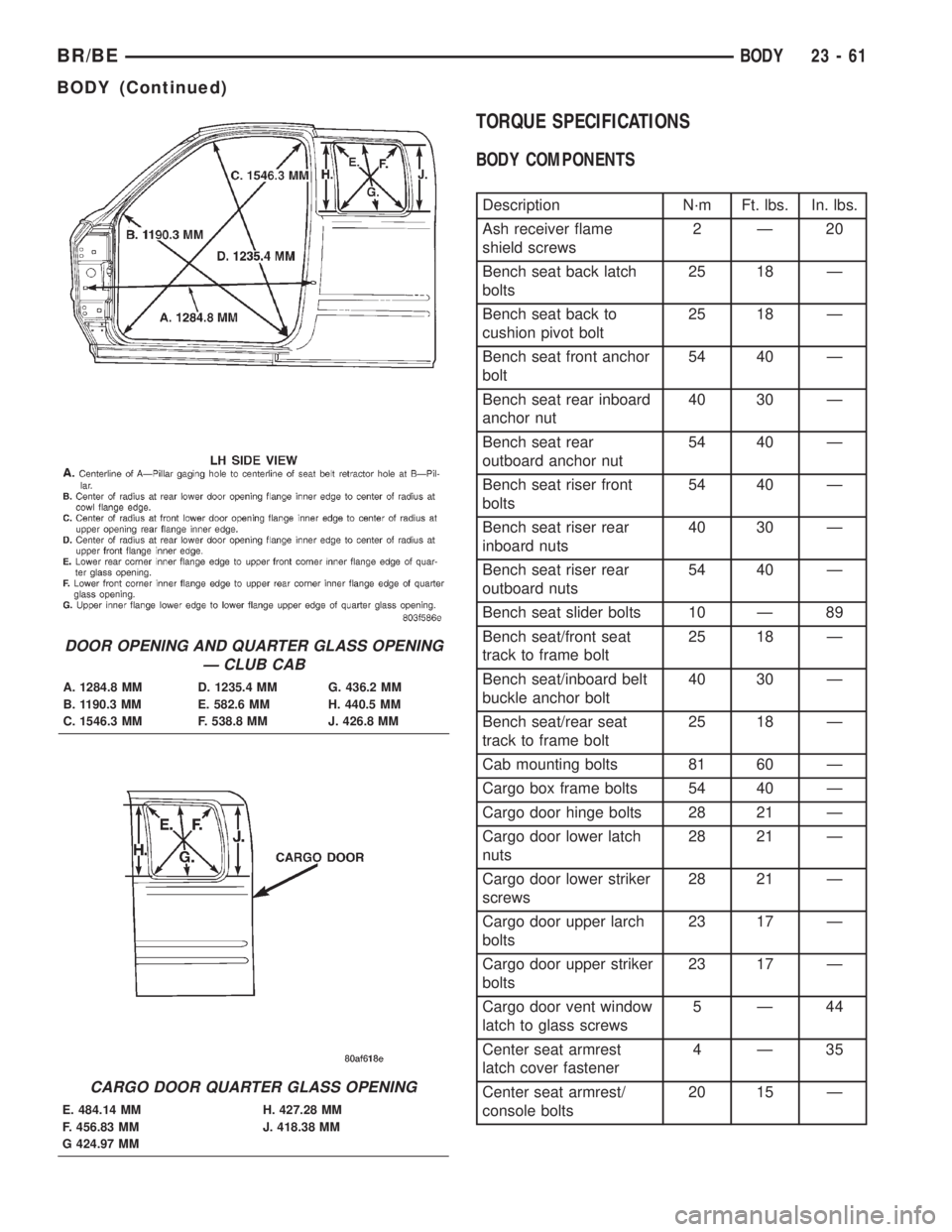
TORQUE SPECIFICATIONS
BODY COMPONENTS
Description N´m Ft. lbs. In. lbs.
Ash receiver flame
shield screws2Ð20
Bench seat back latch
bolts25 18 Ð
Bench seat back to
cushion pivot bolt25 18 Ð
Bench seat front anchor
bolt54 40 Ð
Bench seat rear inboard
anchor nut40 30 Ð
Bench seat rear
outboard anchor nut54 40 Ð
Bench seat riser front
bolts54 40 Ð
Bench seat riser rear
inboard nuts40 30 Ð
Bench seat riser rear
outboard nuts54 40 Ð
Bench seat slider bolts 10 Ð 89
Bench seat/front seat
track to frame bolt25 18 Ð
Bench seat/inboard belt
buckle anchor bolt40 30 Ð
Bench seat/rear seat
track to frame bolt25 18 Ð
Cab mounting bolts 81 60 Ð
Cargo box frame bolts 54 40 Ð
Cargo door hinge bolts 28 21 Ð
Cargo door lower latch
nuts28 21 Ð
Cargo door lower striker
screws28 21 Ð
Cargo door upper larch
bolts23 17 Ð
Cargo door upper striker
bolts23 17 Ð
Cargo door vent window
latch to glass screws5Ð44
Center seat armrest
latch cover fastener4Ð35
Center seat armrest/
console bolts20 15 Ð
DOOR OPENING AND QUARTER GLASS OPENING
Ð CLUB CAB
A. 1284.8 MM D. 1235.4 MM G. 436.2 MM
B. 1190.3 MM E. 582.6 MM H. 440.5 MM
C. 1546.3 MM F. 538.8 MM J. 426.8 MM
CARGO DOOR QUARTER GLASS OPENING
E. 484.14 MM H. 427.28 MM
F. 456.83 MM J. 418.38 MM
G 424.97 MM
BR/BEBODY 23 - 61
BODY (Continued)
Page 2085 of 2255
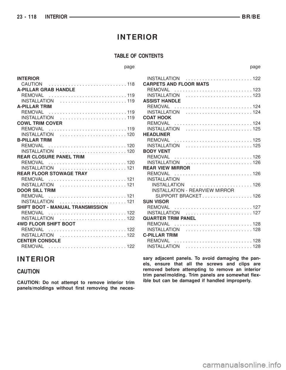
INTERIOR
TABLE OF CONTENTS
page page
INTERIOR
CAUTION............................118
A-PILLAR GRAB HANDLE
REMOVAL............................119
INSTALLATION........................119
A-PILLAR TRIM
REMOVAL............................119
INSTALLATION........................119
COWL TRIM COVER
REMOVAL............................119
INSTALLATION........................120
B-PILLAR TRIM
REMOVAL............................120
INSTALLATION........................120
REAR CLOSURE PANEL TRIM
REMOVAL............................120
INSTALLATION........................121
REAR FLOOR STOWAGE TRAY
REMOVAL............................121
INSTALLATION........................121
DOOR SILL TRIM
REMOVAL............................121
INSTALLATION........................121
SHIFT BOOT - MANUAL TRANSMISSION
REMOVAL............................122
INSTALLATION........................122
4WD FLOOR SHIFT BOOT
REMOVAL............................122
INSTALLATION........................122
CENTER CONSOLE
REMOVAL............................122INSTALLATION........................122
CARPETS AND FLOOR MATS
REMOVAL............................123
INSTALLATION........................123
ASSIST HANDLE
REMOVAL............................124
INSTALLATION........................124
COAT HOOK
REMOVAL............................124
INSTALLATION........................125
HEADLINER
REMOVAL............................125
INSTALLATION........................125
BODY VENT
REMOVAL............................126
INSTALLATION........................126
REAR VIEW MIRROR
REMOVAL............................126
INSTALLATION
INSTALLATION......................126
INSTALLATION - REARVIEW MIRROR
SUPPORT BRACKET..................126
SUN VISOR
REMOVAL............................127
INSTALLATION........................127
QUARTER TRIM PANEL
REMOVAL............................128
INSTALLATION........................128
C-PILLAR TRIM
REMOVAL............................128
INSTALLATION........................128
INTERIOR
CAUTION
CAUTION: Do not attempt to remove interior trim
panels/moldings without first removing the neces-sary adjacent panels. To avoid damaging the pan-
els, ensure that all the screws and clips are
removed before attempting to remove an interior
trim panel/molding. Trim panels are somewhat flex-
ible but can be damaged if handled improperly.
23 - 118 INTERIORBR/BE
Page 2089 of 2255
SHIFT BOOT - MANUAL
TRANSMISSION
REMOVAL
(1) Using a trim stick C-4755 or equivalent, pry
the corner of the shift boot up expose the fasteners.
(2) Remove the screws attaching the shift boot to
the console.
(3) Remove the insert from the shift knob, remove
nut attaching knob to the lever, and remove the shift
knob.
(4) Lift floor shift boot off shifter.
INSTALLATION
(1) Install shift boot over the shift lever, position
boot on console and install the fasteners attaching
boot to concole.
(2) Install the shift knob, shift knob nut, and
tighten to 27 N´m (20 ft.lbs) torque.
(3) Install the shift knob insert.
4WD FLOOR SHIFT BOOT
REMOVAL
(1) Remove insert from shift knob.
(2) Remove nut attaching shift knob to shift lever.
(3) Remove shift knob.
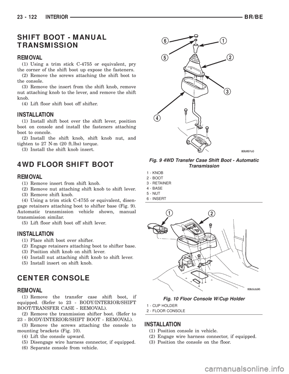
(4) Using a trim stick C-4755 or equivalent, disen-
gage retainers attaching boot to shifter base (Fig. 9).
Automatic transmission vehicle shown, manual
transmission similar.
(5) Lift floor shift boot off shift lever.
INSTALLATION
(1) Place shift boot over shifter.
(2) Engage retainers attaching boot to shifter base.
(3) Position shift knob on shift lever.
(4) Install nut attaching shift knob to shift lever.
(5) Install insert on shift knob.
CENTER CONSOLE
REMOVAL
(1) Remove the transfer case shift boot, if
equipped. (Refer to 23 - BODY/INTERIOR/SHIFT
BOOT/TRANSFER CASE - REMOVAL).
(2) Remove the tranmission shifter boot. (Refer to
23 - BODY/INTERIOR/SHIFT BOOT - REMOVAL).
(3) Remove the screws attaching the console to
mounting brackets (Fig. 10).
(4) Lift the console upward.
(5) Disengage wire harness connector, if equipped.
(6) Separate console from vehicle.
INSTALLATION
(1) Position console in vehicle.
(2) Engage wire harness connector, if equipped.
(3) Position the console on the floor.
Fig. 9 4WD Transfer Case Shift Boot - Automatic
Transmission
1 - KNOB
2 - BOOT
3 - RETAINER
4 - BASE
5 - NUT
6 - INSERT
Fig. 10 Floor Console W/Cup Holder
1 - CUP HOLDER
2 - FLOOR CONSOLE
23 - 122 INTERIORBR/BE
Page 2090 of 2255
(4) Install the screws attaching the console to
mounting brackets.
(5) Install the transmission shifter boot, (Refer to
23 - BODY/INTERIOR/SHIFT BOOT - INSTALLA-
TION).
(6) Install the transfer case shifter boot, if
equipped. (Refer to 23 - BODY/INTERIOR/SHIFT
BOOT - INSTALLATION).
(7) Install cup holder in console, if equipped.
CARPETS AND FLOOR MATS
REMOVAL
STANDARD CAB
(1) Remove seat (Refer to 23 - BODY/SEATS/SEAT
- BENCH SEAT - REMOVAL) or(Refer to 23 - BODY/
SEATS/SEAT - SPLIT BENCH - REMOVAL).
(2) Remove door sill covers (Refer to 23 - BODY/
INTERIOR/DOOR SILL TRIM - REMOVAL).
(3) Remove cowl trim covers (Refer to 23 - BODY/
INTERIOR/COWL TRIM COVER - REMOVAL).
(4) Remove center console, if equipped.(Refer to 23
- BODY/INTERIOR/CENTER CONSOLE -
REMOVAL)
(5) If not equipped with a center console remove
the transfer case shifter boot (Refer to 23 - BODY/IN-
TERIOR/SHIFT BOOT/TRANSFER CASE - REMOV-
AL).
(6) Remove rear stowage tray (Refer to 23 - BODY/
INTERIOR/REAR FLOOR STOWAGE TRAY -
REMOVAL).
(7) Remove rear closure panel trim (Refer to 23 -
BODY/INTERIOR/REAR CLOSURE PANEL TRIM -
REMOVAL).
(8) Fold carpet or mat toward center of cab.
(9) Remove carpet or mat through door opening
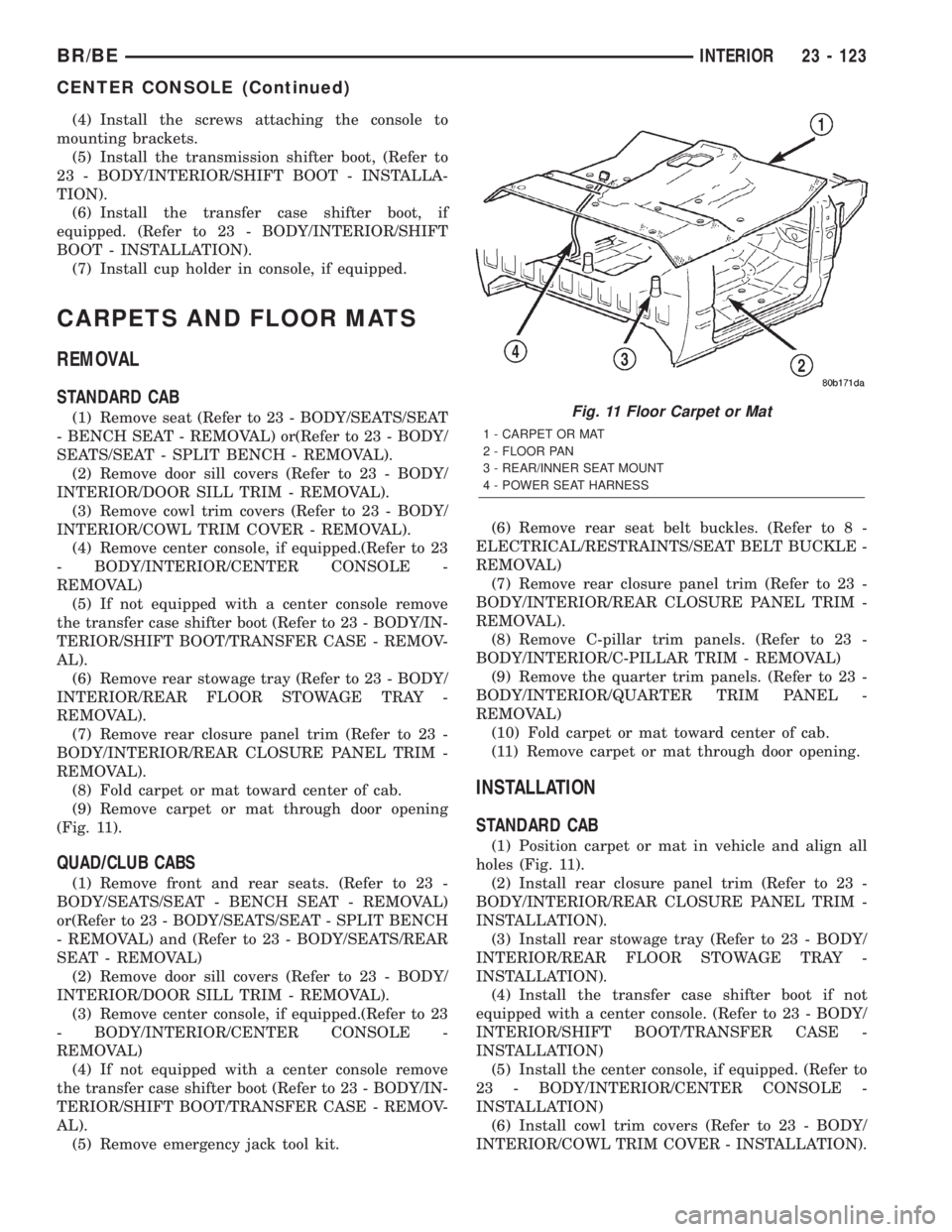
(Fig. 11).
QUAD/CLUB CABS
(1) Remove front and rear seats. (Refer to 23 -
BODY/SEATS/SEAT - BENCH SEAT - REMOVAL)
or(Refer to 23 - BODY/SEATS/SEAT - SPLIT BENCH
- REMOVAL) and (Refer to 23 - BODY/SEATS/REAR
SEAT - REMOVAL)
(2) Remove door sill covers (Refer to 23 - BODY/
INTERIOR/DOOR SILL TRIM - REMOVAL).
(3) Remove center console, if equipped.(Refer to 23
- BODY/INTERIOR/CENTER CONSOLE -
REMOVAL)
(4) If not equipped with a center console remove
the transfer case shifter boot (Refer to 23 - BODY/IN-
TERIOR/SHIFT BOOT/TRANSFER CASE - REMOV-
AL).
(5) Remove emergency jack tool kit.(6) Remove rear seat belt buckles. (Refer to 8 -
ELECTRICAL/RESTRAINTS/SEAT BELT BUCKLE -
REMOVAL)
(7) Remove rear closure panel trim (Refer to 23 -
BODY/INTERIOR/REAR CLOSURE PANEL TRIM -
REMOVAL).
(8) Remove C-pillar trim panels. (Refer to 23 -
BODY/INTERIOR/C-PILLAR TRIM - REMOVAL)
(9) Remove the quarter trim panels. (Refer to 23 -
BODY/INTERIOR/QUARTER TRIM PANEL -
REMOVAL)
(10) Fold carpet or mat toward center of cab.
(11) Remove carpet or mat through door opening.
INSTALLATION
STANDARD CAB
(1) Position carpet or mat in vehicle and align all
holes (Fig. 11).
(2) Install rear closure panel trim (Refer to 23 -
BODY/INTERIOR/REAR CLOSURE PANEL TRIM -
INSTALLATION).
(3) Install rear stowage tray (Refer to 23 - BODY/
INTERIOR/REAR FLOOR STOWAGE TRAY -
INSTALLATION).
(4) Install the transfer case shifter boot if not
equipped with a center console. (Refer to 23 - BODY/
INTERIOR/SHIFT BOOT/TRANSFER CASE -
INSTALLATION)
(5) Install the center console, if equipped. (Refer to
23 - BODY/INTERIOR/CENTER CONSOLE -
INSTALLATION)
(6) Install cowl trim covers (Refer to 23 - BODY/
INTERIOR/COWL TRIM COVER - INSTALLATION).
Fig. 11 Floor Carpet or Mat
1 - CARPET OR MAT
2 - FLOOR PAN
3 - REAR/INNER SEAT MOUNT
4 - POWER SEAT HARNESS
BR/BEINTERIOR 23 - 123
CENTER CONSOLE (Continued)
Page 2091 of 2255
(7) Install door sill covers (Refer to 23 - BODY/IN-
TERIOR/DOOR SILL TRIM - INSTALLATION).
(8) Install seat, (Refer to 23 - BODY/SEATS/SEAT
- INSTALLATION) or (Refer to 23 - BODY/SEATS/
SEAT/SPLIT BENCH - INSTALLATION).
QUAD/CLUB CABS
(1) Position carpet or mat in vehicle.
(2) Install quarter trim panels. (Refer to 23 -
BODY/INTERIOR/QUARTER TRIM PANEL -
INSTALLATION)
(3) Install rear seat belt buckles.
(4) Install the C-pillar trim panels, if equipped.
(Refer to 23 - BODY/INTERIOR/C-PILLAR TRIM -
INSTALLATION)
(5) Install rear closure panel trim (Refer to 23 -
BODY/INTERIOR/REAR CLOSURE PANEL TRIM -
INSTALLATION).
(6) Install the rear seat belt buckles. (Refer to 8 -
ELECTRICAL/RESTRAINTS/SEAT BELT BUCKLE -
INSTALLATION)
(7) Install emergency jack tool kit.
(8) Install the transfer case shifter boot if not
equipped with a center console. (Refer to 23 - BODY/
INTERIOR/SHIFT BOOT/TRANSFER CASE -
INSTALLATION)
(9) Install the center console, if equipped. (Refer to
23 - BODY/INTERIOR/CENTER CONSOLE -
INSTALLATION)
(10) Install floor shift boot, if equipped.
(11) Install cowl trim covers (Refer to 23 - BODY/
INTERIOR/COWL TRIM COVER - INSTALLATION).
(12) Install door sill covers (Refer to 23 - BODY/
INTERIOR/DOOR SILL TRIM - INSTALLATION).
(13) Install front and rear seats. (Refer to 23 -
BODY/SEATS/SEAT - BENCH SEAT - INSTALLA-
TION) or (Refer to 23 - BODY/SEATS/SEAT - SPLIT
BENCH - INSTALLATION) and (Refer to 23 - BODY/
SEATS/REAR SEAT - INSTALLATION)
ASSIST HANDLE
REMOVAL
(1) Disengage tabs attaching assist handle end
covers to assist handle.
(2) Remove screws attaching overhead assist han-
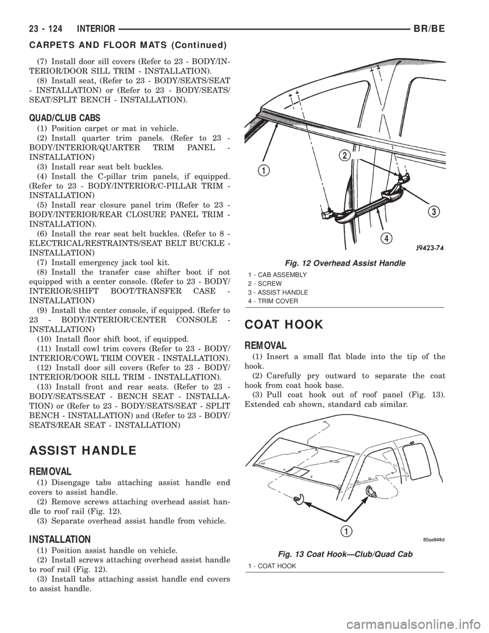
dle to roof rail (Fig. 12).
(3) Separate overhead assist handle from vehicle.
INSTALLATION
(1) Position assist handle on vehicle.
(2) Install screws attaching overhead assist handle
to roof rail (Fig. 12).
(3) Install tabs attaching assist handle end covers
to assist handle.
COAT HOOK
REMOVAL
(1) Insert a small flat blade into the tip of the
hook.
(2) Carefully pry outward to separate the coat
hook from coat hook base.
(3) Pull coat hook out of roof panel (Fig. 13).
Extended cab shown, standard cab similar.
Fig. 12 Overhead Assist Handle
1 - CAB ASSEMBLY
2 - SCREW
3 - ASSIST HANDLE
4 - TRIM COVER
Fig. 13 Coat HookÐClub/Quad Cab
1 - COAT HOOK
23 - 124 INTERIORBR/BE
CARPETS AND FLOOR MATS (Continued)
Page 2098 of 2255
SEATS
TABLE OF CONTENTS
page page
SEATS
DESCRIPTION........................131
OPERATION..........................131
CENTER CONSOLE LID
REMOVAL............................131
INSTALLATION........................132
CENTER SEAT ARMREST/CONSOLE
REMOVAL............................132
INSTALLATION........................132
CENTER SEAT ARMREST/LATCH COVER
REMOVAL............................132
INSTALLATION........................132
LUMBAR SUPPORT
REMOVAL............................132
INSTALLATION........................133
SEAT - BENCH SEAT
REMOVAL............................133
INSTALLATION........................133
SEAT - SPLIT BENCH
REMOVAL............................133
INSTALLATION........................134
SEAT BACK - BENCH SEAT
REMOVAL............................135
INSTALLATION........................135
SEAT BACK - SPLIT BENCH
REMOVAL............................135
INSTALLATION........................136
SEAT BACK COVER
REMOVAL............................137
INSTALLATION........................137
SEAT BACK COVER - SPLIT BENCH
REMOVAL............................137
INSTALLATION........................137SEAT BACK RECLINER
REMOVAL............................138
INSTALLATION........................138
SEAT CUSHION
REMOVAL............................138
INSTALLATION........................138
SEAT CUSHION COVER
REMOVAL............................139
INSTALLATION........................139
SEAT CUSHION COVER - SPLIT BENCH
REMOVAL............................139
INSTALLATION........................140
SEAT RISER
REMOVAL............................141
INSTALLATION........................141
SEAT TRACK
REMOVAL............................141
INSTALLATION........................141
SEAT TRACK - SPLIT BENCH
REMOVAL............................142
INSTALLATION........................142
EASY ENTRY SEAT TRACK
REMOVAL............................143
INSTALLATION........................143
SEAT TRACK ADJUSTER
REMOVAL............................143
INSTALLATION........................143
STANCHION COVER
REMOVAL............................143
INSTALLATION........................143
REAR SEAT
REMOVAL............................144
INSTALLATION........................144
SEATS
DESCRIPTION
Seat modules are made up of a seat frame, seat
cushion, seat back cushion, a covering material, and
the electrical components used for power operation, if
equipped. Some seat systems also contain seat belt
components and supplemental restraint systems.
OPERATION
Seat assemblies transport the occupants in comfort
and safety. Seat assemblies also help position occupants
correctly in the event of airbag deployment. Seat cush-
ions, coverings, and electrical components are service-
able. Refer to the appropriate group in this manual.
CENTER CONSOLE LID
REMOVAL
(1) Open console lid.
(2) Using a small flat blade screwdriver, disengage
locking tabs located under the console lid trim bezel.
(3) Separate bezel from lid.
(4) Move driver and passenger seat to full forward
position.
(5) Using a small drift and hammer, tap out con-
sole lid hinge pin.
(6) Separate lid from console.
BR/BESEATS 23 - 131