2002 DODGE RAM high beam
[x] Cancel search: high beamPage 530 of 2255
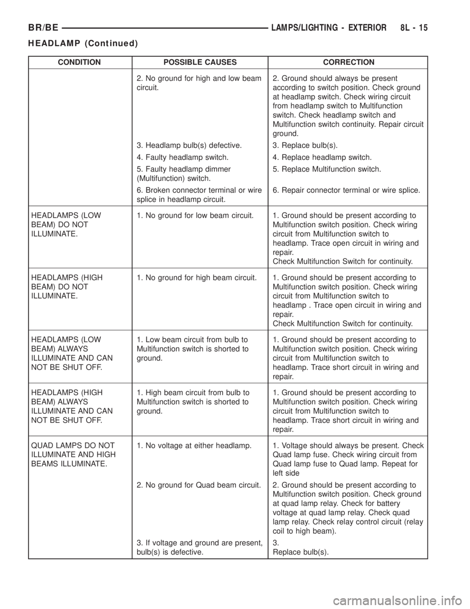
CONDITION POSSIBLE CAUSES CORRECTION
2. No ground for high and low beam
circuit.2. Ground should always be present
according to switch position. Check ground
at headlamp switch. Check wiring circuit
from headlamp switch to Multifunction
switch. Check headlamp switch and
Multifunction switch continuity. Repair circuit
ground.
3. Headlamp bulb(s) defective. 3. Replace bulb(s).
4. Faulty headlamp switch. 4. Replace headlamp switch.
5. Faulty headlamp dimmer
(Multifunction) switch.5. Replace Multifunction switch.
6. Broken connector terminal or wire
splice in headlamp circuit.6. Repair connector terminal or wire splice.
HEADLAMPS (LOW
BEAM) DO NOT
ILLUMINATE.1. No ground for low beam circuit. 1. Ground should be present according to
Multifunction switch position. Check wiring
circuit from Multifunction switch to
headlamp. Trace open circuit in wiring and
repair.
Check Multifunction Switch for continuity.
HEADLAMPS (HIGH
BEAM) DO NOT
ILLUMINATE.1. No ground for high beam circuit. 1. Ground should be present according to
Multifunction switch position. Check wiring
circuit from Multifunction switch to
headlamp . Trace open circuit in wiring and
repair.
Check Multifunction Switch for continuity.
HEADLAMPS (LOW
BEAM) ALWAYS
ILLUMINATE AND CAN
NOT BE SHUT OFF.1. Low beam circuit from bulb to
Multifunction switch is shorted to
ground.1. Ground should be present according to
Multifunction switch position. Check wiring
circuit from Multifunction switch to
headlamp. Trace short circuit in wiring and
repair.
HEADLAMPS (HIGH
BEAM) ALWAYS
ILLUMINATE AND CAN
NOT BE SHUT OFF.1. High beam circuit from bulb to
Multifunction switch is shorted to
ground.1. Ground should be present according to
Multifunction switch position. Check wiring
circuit from Multifunction switch to
headlamp. Trace short circuit in wiring and
repair.
QUAD LAMPS DO NOT
ILLUMINATE AND HIGH
BEAMS ILLUMINATE.1. No voltage at either headlamp. 1. Voltage should always be present. Check
Quad lamp fuse. Check wiring circuit from
Quad lamp fuse to Quad lamp. Repeat for
left side
2. No ground for Quad beam circuit. 2. Ground should be present according to
Multifunction switch position. Check ground
at quad lamp relay. Check for battery
voltage at quad lamp relay. Check quad
lamp relay. Check relay control circuit (relay
coil to high beam).
3. If voltage and ground are present,
bulb(s) is defective.3.
Replace bulb(s).
BR/BELAMPS/LIGHTING - EXTERIOR 8L - 15
HEADLAMP (Continued)
Page 531 of 2255
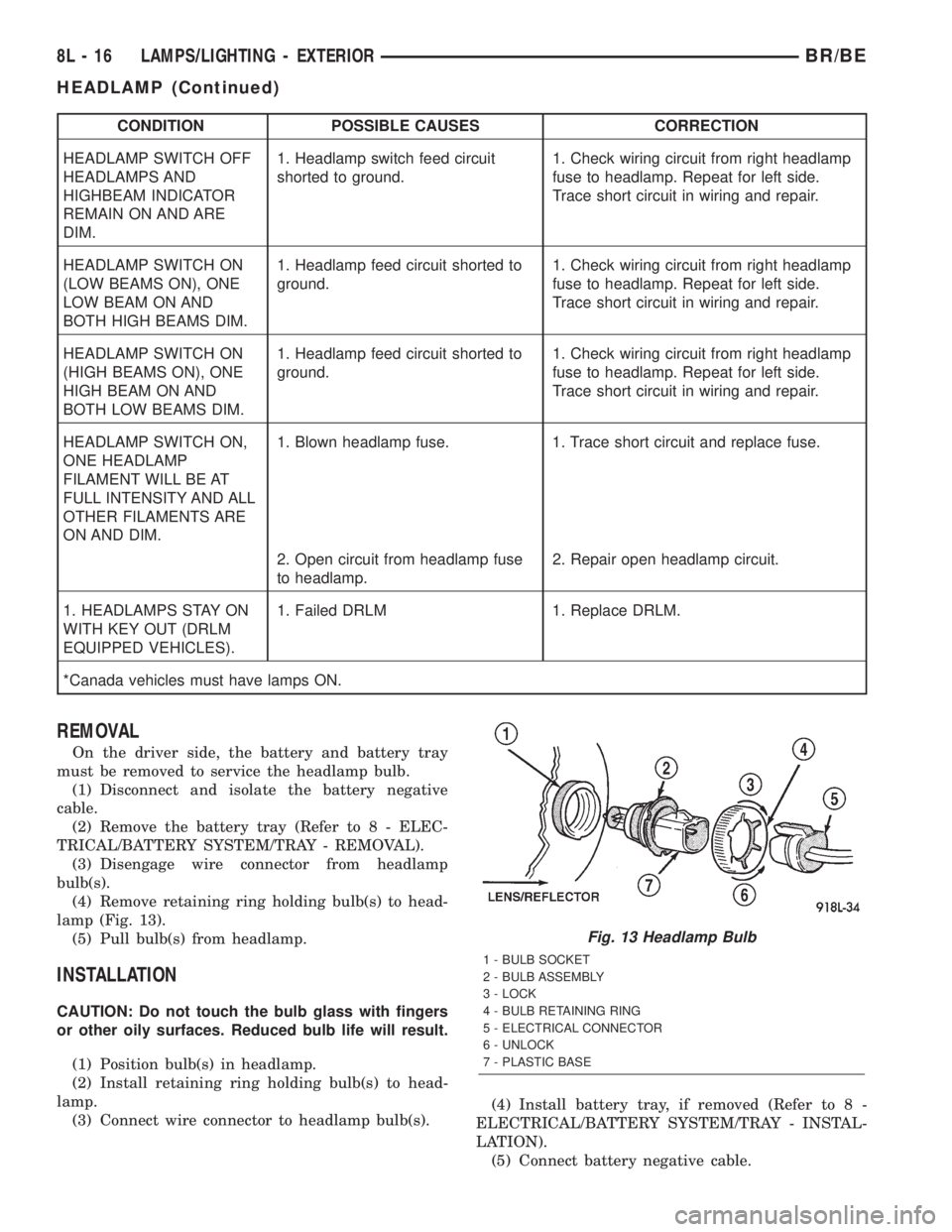
CONDITION POSSIBLE CAUSES CORRECTION
HEADLAMP SWITCH OFF
HEADLAMPS AND
HIGHBEAM INDICATOR
REMAIN ON AND ARE
DIM.1. Headlamp switch feed circuit
shorted to ground.1. Check wiring circuit from right headlamp
fuse to headlamp. Repeat for left side.
Trace short circuit in wiring and repair.
HEADLAMP SWITCH ON
(LOW BEAMS ON), ONE
LOW BEAM ON AND
BOTH HIGH BEAMS DIM.1. Headlamp feed circuit shorted to
ground.1. Check wiring circuit from right headlamp
fuse to headlamp. Repeat for left side.
Trace short circuit in wiring and repair.
HEADLAMP SWITCH ON
(HIGH BEAMS ON), ONE
HIGH BEAM ON AND
BOTH LOW BEAMS DIM.1. Headlamp feed circuit shorted to
ground.1. Check wiring circuit from right headlamp
fuse to headlamp. Repeat for left side.
Trace short circuit in wiring and repair.
HEADLAMP SWITCH ON,
ONE HEADLAMP
FILAMENT WILL BE AT
FULL INTENSITY AND ALL
OTHER FILAMENTS ARE
ON AND DIM.1. Blown headlamp fuse. 1. Trace short circuit and replace fuse.
2. Open circuit from headlamp fuse
to headlamp.2. Repair open headlamp circuit.
1. HEADLAMPS STAY ON
WITH KEY OUT (DRLM
EQUIPPED VEHICLES).1. Failed DRLM 1. Replace DRLM.
*Canada vehicles must have lamps ON.
REMOVAL
On the driver side, the battery and battery tray
must be removed to service the headlamp bulb.
(1) Disconnect and isolate the battery negative
cable.
(2) Remove the battery tray (Refer to 8 - ELEC-
TRICAL/BATTERY SYSTEM/TRAY - REMOVAL).
(3) Disengage wire connector from headlamp
bulb(s).
(4) Remove retaining ring holding bulb(s) to head-
lamp (Fig. 13).
(5) Pull bulb(s) from headlamp.
INSTALLATION
CAUTION: Do not touch the bulb glass with fingers
or other oily surfaces. Reduced bulb life will result.
(1) Position bulb(s) in headlamp.
(2) Install retaining ring holding bulb(s) to head-
lamp.
(3) Connect wire connector to headlamp bulb(s).(4) Install battery tray, if removed (Refer to 8 -
ELECTRICAL/BATTERY SYSTEM/TRAY - INSTAL-
LATION).
(5) Connect battery negative cable.
Fig. 13 Headlamp Bulb
1 - BULB SOCKET
2 - BULB ASSEMBLY
3 - LOCK
4 - BULB RETAINING RING
5 - ELECTRICAL CONNECTOR
6 - UNLOCK
7 - PLASTIC BASE
8L - 16 LAMPS/LIGHTING - EXTERIORBR/BE
HEADLAMP (Continued)
Page 532 of 2255
HEADLAMP RELAY
DESCRIPTION
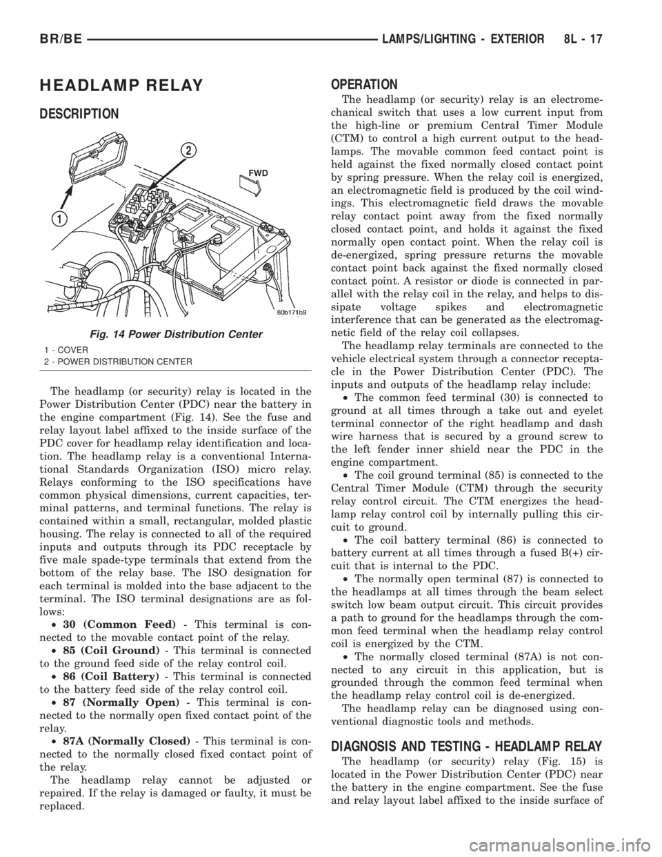
The headlamp (or security) relay is located in the
Power Distribution Center (PDC) near the battery in
the engine compartment (Fig. 14). See the fuse and
relay layout label affixed to the inside surface of the
PDC cover for headlamp relay identification and loca-
tion. The headlamp relay is a conventional Interna-
tional Standards Organization (ISO) micro relay.
Relays conforming to the ISO specifications have
common physical dimensions, current capacities, ter-
minal patterns, and terminal functions. The relay is
contained within a small, rectangular, molded plastic
housing. The relay is connected to all of the required
inputs and outputs through its PDC receptacle by
five male spade-type terminals that extend from the
bottom of the relay base. The ISO designation for
each terminal is molded into the base adjacent to the
terminal. The ISO terminal designations are as fol-
lows:
²30 (Common Feed)- This terminal is con-
nected to the movable contact point of the relay.
²85 (Coil Ground)- This terminal is connected
to the ground feed side of the relay control coil.
²86 (Coil Battery)- This terminal is connected
to the battery feed side of the relay control coil.
²87 (Normally Open)- This terminal is con-
nected to the normally open fixed contact point of the
relay.
²87A (Normally Closed)- This terminal is con-
nected to the normally closed fixed contact point of
the relay.
The headlamp relay cannot be adjusted or
repaired. If the relay is damaged or faulty, it must be
replaced.
OPERATION
The headlamp (or security) relay is an electrome-
chanical switch that uses a low current input from
the high-line or premium Central Timer Module
(CTM) to control a high current output to the head-
lamps. The movable common feed contact point is
held against the fixed normally closed contact point
by spring pressure. When the relay coil is energized,
an electromagnetic field is produced by the coil wind-
ings. This electromagnetic field draws the movable
relay contact point away from the fixed normally
closed contact point, and holds it against the fixed
normally open contact point. When the relay coil is
de-energized, spring pressure returns the movable
contact point back against the fixed normally closed
contact point. A resistor or diode is connected in par-
allel with the relay coil in the relay, and helps to dis-
sipate voltage spikes and electromagnetic
interference that can be generated as the electromag-
netic field of the relay coil collapses.
The headlamp relay terminals are connected to the
vehicle electrical system through a connector recepta-
cle in the Power Distribution Center (PDC). The
inputs and outputs of the headlamp relay include:
²The common feed terminal (30) is connected to
ground at all times through a take out and eyelet
terminal connector of the right headlamp and dash
wire harness that is secured by a ground screw to
the left fender inner shield near the PDC in the
engine compartment.
²The coil ground terminal (85) is connected to the
Central Timer Module (CTM) through the security
relay control circuit. The CTM energizes the head-
lamp relay control coil by internally pulling this cir-
cuit to ground.
²The coil battery terminal (86) is connected to
battery current at all times through a fused B(+) cir-
cuit that is internal to the PDC.
²The normally open terminal (87) is connected to
the headlamps at all times through the beam select
switch low beam output circuit. This circuit provides
a path to ground for the headlamps through the com-
mon feed terminal when the headlamp relay control
coil is energized by the CTM.
²The normally closed terminal (87A) is not con-
nected to any circuit in this application, but is
grounded through the common feed terminal when
the headlamp relay control coil is de-energized.
The headlamp relay can be diagnosed using con-
ventional diagnostic tools and methods.
DIAGNOSIS AND TESTING - HEADLAMP RELAY
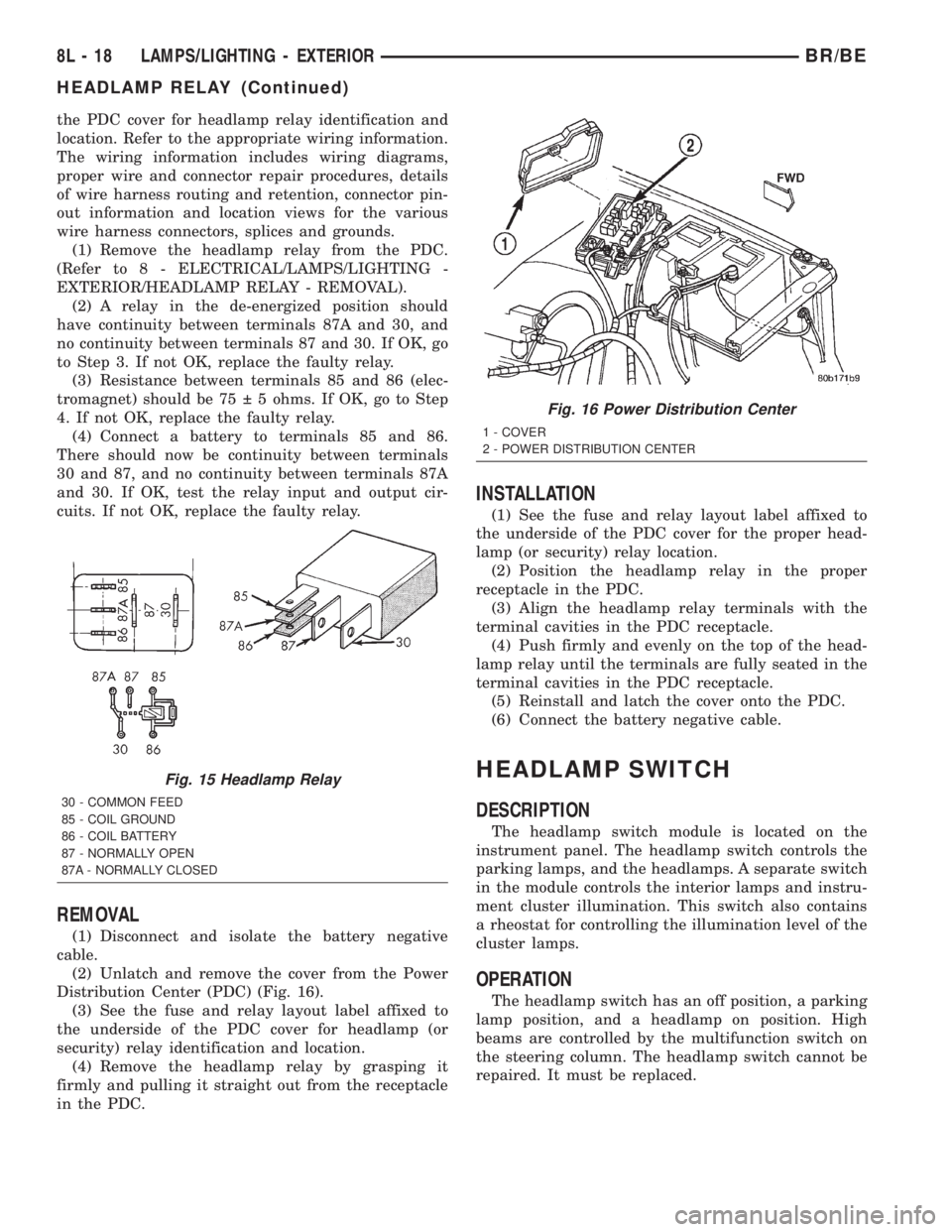
The headlamp (or security) relay (Fig. 15) is
located in the Power Distribution Center (PDC) near
the battery in the engine compartment. See the fuse
and relay layout label affixed to the inside surface of
Fig. 14 Power Distribution Center
1 - COVER
2 - POWER DISTRIBUTION CENTER
BR/BELAMPS/LIGHTING - EXTERIOR 8L - 17
Page 533 of 2255
the PDC cover for headlamp relay identification and
location. Refer to the appropriate wiring information.
The wiring information includes wiring diagrams,
proper wire and connector repair procedures, details
of wire harness routing and retention, connector pin-
out information and location views for the various
wire harness connectors, splices and grounds.
(1) Remove the headlamp relay from the PDC.
(Refer to 8 - ELECTRICAL/LAMPS/LIGHTING -
EXTERIOR/HEADLAMP RELAY - REMOVAL).
(2) A relay in the de-energized position should
have continuity between terminals 87A and 30, and
no continuity between terminals 87 and 30. If OK, go
to Step 3. If not OK, replace the faulty relay.
(3) Resistance between terminals 85 and 86 (elec-
tromagnet) should be 75 5 ohms. If OK, go to Step
4. If not OK, replace the faulty relay.
(4) Connect a battery to terminals 85 and 86.
There should now be continuity between terminals
30 and 87, and no continuity between terminals 87A
and 30. If OK, test the relay input and output cir-
cuits. If not OK, replace the faulty relay.
REMOVAL
(1) Disconnect and isolate the battery negative
cable.
(2) Unlatch and remove the cover from the Power
Distribution Center (PDC) (Fig. 16).
(3) See the fuse and relay layout label affixed to
the underside of the PDC cover for headlamp (or
security) relay identification and location.
(4) Remove the headlamp relay by grasping it
firmly and pulling it straight out from the receptacle
in the PDC.
INSTALLATION
(1) See the fuse and relay layout label affixed to
the underside of the PDC cover for the proper head-
lamp (or security) relay location.
(2) Position the headlamp relay in the proper
receptacle in the PDC.
(3) Align the headlamp relay terminals with the
terminal cavities in the PDC receptacle.
(4) Push firmly and evenly on the top of the head-
lamp relay until the terminals are fully seated in the
terminal cavities in the PDC receptacle.
(5) Reinstall and latch the cover onto the PDC.
(6) Connect the battery negative cable.
HEADLAMP SWITCH
DESCRIPTION
The headlamp switch module is located on the
instrument panel. The headlamp switch controls the
parking lamps, and the headlamps. A separate switch
in the module controls the interior lamps and instru-
ment cluster illumination. This switch also contains
a rheostat for controlling the illumination level of the
cluster lamps.
OPERATION
The headlamp switch has an off position, a parking
lamp position, and a headlamp on position. High
beams are controlled by the multifunction switch on
the steering column. The headlamp switch cannot be
repaired. It must be replaced.
Fig. 15 Headlamp Relay
30 - COMMON FEED
85 - COIL GROUND
86 - COIL BATTERY
87 - NORMALLY OPEN
87A - NORMALLY CLOSED
Fig. 16 Power Distribution Center
1 - COVER
2 - POWER DISTRIBUTION CENTER
8L - 18 LAMPS/LIGHTING - EXTERIORBR/BE
HEADLAMP RELAY (Continued)
Page 535 of 2255
(4) Pull the headlamp switch away from the
instrument panel far enough to access the instru-
ment panel wire harness connectors.
(5) Disconnect the two instrument panel wire har-
ness connectors for the headlamp switch from the
connector receptacles on the back of the switch.
(6) Remove the headlamp switch from the instru-
ment panel.
INSTALLATION
WARNING: ON VEHICLES EQUIPPED WITH AIR-
BAGS, DISABLE THE AIRBAG SYSTEM BEFORE
ATTEMPTING ANY STEERING WHEEL, STEERING
COLUMN, OR INSTRUMENT PANEL COMPONENT
DIAGNOSIS OR SERVICE. DISCONNECT AND ISO-
LATE THE BATTERY NEGATIVE (GROUND) CABLE,
THEN WAIT TWO MINUTES FOR THE AIRBAG SYS-
TEM CAPACITOR TO DISCHARGE BEFORE PER-
FORMING FURTHER DIAGNOSIS OR SERVICE. THIS
IS THE ONLY SURE WAY TO DISABLE THE AIRBAG
SYSTEM. FAILURE TO TAKE THE PROPER PRE-
CAUTIONS COULD RESULT IN ACCIDENTAL AIR-
BAG DEPLOYMENT AND POSSIBLE PERSONAL
INJURY.
(1) Position the headlamp switch to the instru-
ment panel.
(2) Reconnect the two instrument panel wire har-
ness connectors for the headlamp switch to the con-
nector receptacles on the back of the switch.
(3) Position the headlamp switch into the instru-
ment panel.
(4) Install and tighten the three screws that secure
the headlamp switch to the instrument panel.
Tighten the screws to 2.2 N´m (20 in. lbs.).
(5) Reinstall the cluster bezel onto the instrument
panel. (Refer to 23 - BODY/INSTRUMENT PANEL/
CLUSTER BEZEL - INSTALLATION).
(6) Connect the battery negative cable.
HEADLAMP UNIT
REMOVAL
(1) Disconnect and isolate the battery negative
cable.
(2) Remove push-in fastener attaching seal to radi-
ator closure panel.
(3) Remove park and turn signal lamp.
(4) Remove screws attaching top of headlamp mod-
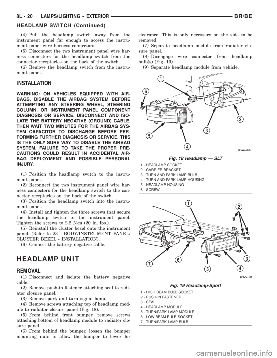
ule to radiator closure panel (Fig. 18).
(5) From behind front bumper, remove screws
attaching bottom of headlamp module to radiator clo-
sure panel.
(6) From behind the bumper, loosen the bumper
mounting nuts to allow the bumper to lower forclearance. This is only necessary on the side to be
removed.
(7) Separate headlamp module from radiator clo-
sure panel.
(8) Disengage wire connector from headlamp
bulb(s) (Fig. 19).
(9) Separate headlamp module from vehicle.
Fig. 18 Headlamp Ð SLT
1 - HEADLAMP SOCKET
2 - CARRIER BRACKET
3 - TURN AND PARK LAMP BULB
4 - TURN AND PARK LAMP HOUSING
5 - HEADLAMP HOUSING
6 - SCREW
Fig. 19 Headlamp-Sport
1 - HIGH BEAM BULB SOCKET
2 - PUSH-IN FASTENER
3 - SEAL
4 - HEADLAMP MODULE
5 - TURN/PARK LAMP MODULE
6 - LOW BEAM BULB SOCKET
7 - TURN/PARK LAMP BULB
8L - 20 LAMPS/LIGHTING - EXTERIORBR/BE
HEADLAMP SWITCH (Continued)
Page 537 of 2255
VEHICLE PREPARATION FOR HEADLAMP
ALIGNMENT
(1) Verify headlamp dimmer switch and high beam
indicator operation.
(2) Verify headlamps are set for low beam opera-
tion.
(3) Correct defective components that could hinder
proper headlamp alignment.
(4) Verify proper tire inflation.
(5) Clean headlamp lenses.
(6) Verify that luggage area is not heavily loaded.
(7) Fuel tank should be FULL. Add 2.94 kg (6.5
lbs.) of weight over the fuel tank for each estimated
gallon of missing fuel.
HEADLAMP ADJUSTMENT
Headlamps can be aligned using the screen method
provided or alignment tool C-4466±A or equivalent
can be used. refer to the instructions provided with
the tool for proper procedures.
A properly aimed low beam headlamp will project
top edge of high intensity pattern on screen from 50
mm (2 in.) above to 50 mm (2 in.) below headlamp
centerline. The side-to-side outboard edge of high
intensity pattern should be from 50 mm (2 in.) left to
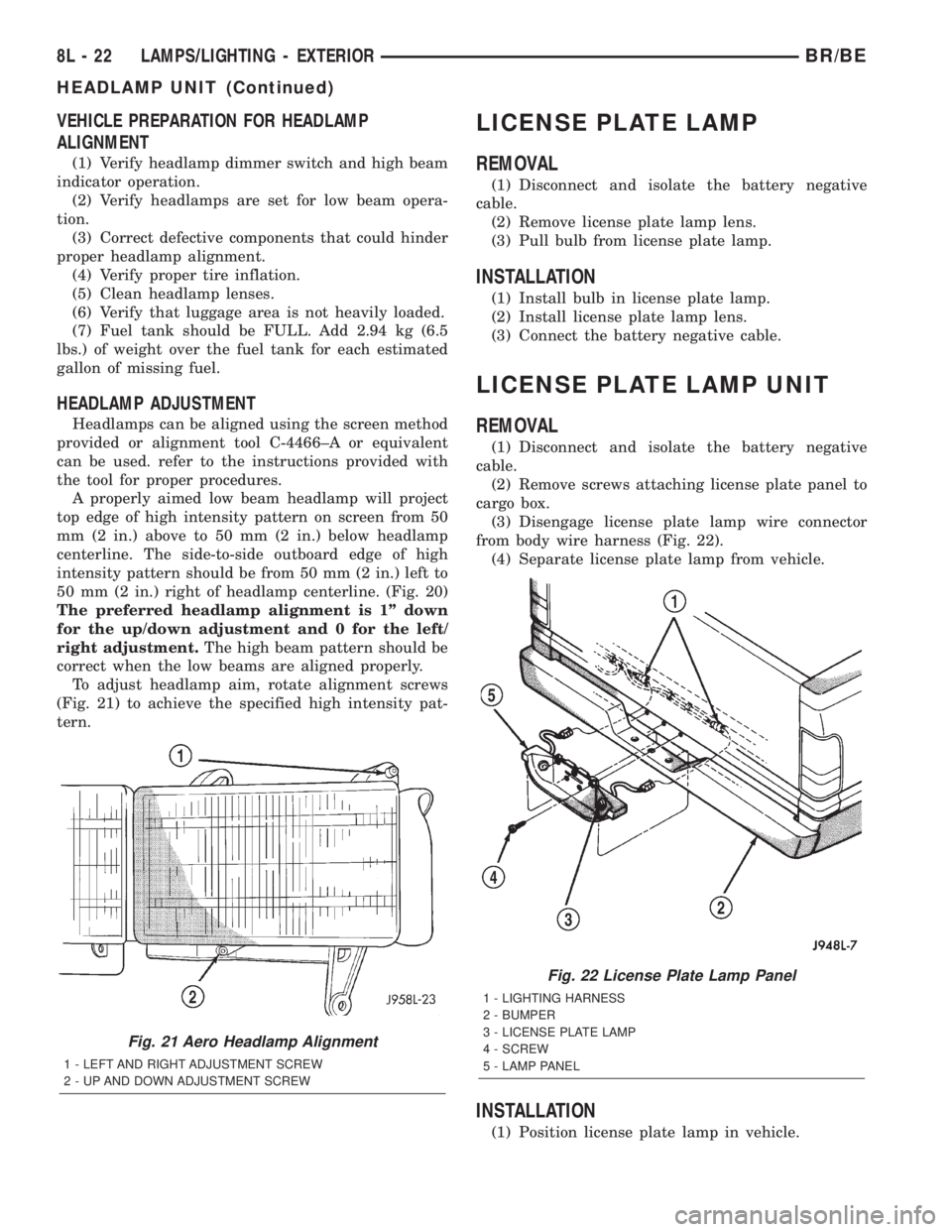
50 mm (2 in.) right of headlamp centerline. (Fig. 20)
The preferred headlamp alignment is 1º down
for the up/down adjustment and 0 for the left/
right adjustment.The high beam pattern should be
correct when the low beams are aligned properly.
To adjust headlamp aim, rotate alignment screws
(Fig. 21) to achieve the specified high intensity pat-
tern.
LICENSE PLATE LAMP
REMOVAL
(1) Disconnect and isolate the battery negative
cable.
(2) Remove license plate lamp lens.
(3) Pull bulb from license plate lamp.
INSTALLATION
(1) Install bulb in license plate lamp.
(2) Install license plate lamp lens.
(3) Connect the battery negative cable.
LICENSE PLATE LAMP UNIT
REMOVAL
(1) Disconnect and isolate the battery negative
cable.
(2) Remove screws attaching license plate panel to
cargo box.
(3) Disengage license plate lamp wire connector
from body wire harness (Fig. 22).
(4) Separate license plate lamp from vehicle.
INSTALLATION
(1) Position license plate lamp in vehicle.
Fig. 21 Aero Headlamp Alignment
1 - LEFT AND RIGHT ADJUSTMENT SCREW
2 - UP AND DOWN ADJUSTMENT SCREW
Fig. 22 License Plate Lamp Panel
1 - LIGHTING HARNESS
2 - BUMPER
3 - LICENSE PLATE LAMP
4 - SCREW
5 - LAMP PANEL
8L - 22 LAMPS/LIGHTING - EXTERIORBR/BE
HEADLAMP UNIT (Continued)
Page 539 of 2255
²Continuous Wipe Modes- The control knob of
the multi-function switch provides two continuous
wipe switch positions, low speed or high speed.
²Hazard Warning Control- The internal cir-
cuitry and hardware of the multi-function switch pro-
vide detent switching for activation and deactivation
of the hazard warning system.
²Headlamp Beam Selection- The internal cir-
cuitry and hardware of the multi-function switch pro-
vide detent switching for selection of the headlamp
high or low beams.
²Headlamp Optical Horn- The internal cir-
cuitry and hardware of the multi-function switch
includes momentary switching of the headlamp high
beam circuits to provide an optical horn feature
(sometimes referred to as flash-to-pass), which allows
the vehicle operator to momentarily flash the head-
lamp high beams as an optical signalling device.
²Intermittent Wipe Mode- The control knob of
the multi-function switch provides an intermittent
wipe mode with multiple delay interval positions.
²Turn Signal Control- The internal circuitry
and hardware of the multi-function switch provide
both momentary non-detent switching and detent
switching with automatic cancellation for both the
left and right turn signals.
²Washer Mode- A button on the end of the con-
trol stalk of the multi-function switch provides
washer system operation when the button is
depressed towards the steering column.
The multi-function switch cannot be adjusted or
repaired. If any function of the switch is faulty, or if
the switch is damaged, the entire switch unit must
be replaced.
OPERATION
The multi-function switch uses conventionally
switched outputs and a variable resistor to control
the many functions and features it provides using
hard wired circuitry. The switch is grounded at all
times through a single wire take out with an eyelet
terminal connector of the instrument panel wire har-
ness that is secured by a nut to a ground stud
located on the instrument panel armature, just above
and to the left of the glove box opening. When the
ignition switch is in the Accessory or On positions,
battery current from a fuse in the Junction Block
(JB) is provided through a fused ignition switch out-
put (run-acc) circuit. Following are descriptions of
how the multi-function switch operates to control the
many functions and features it provides:²Continuous Wipe Modes- When the control
knob of the multi-function switch is rotated to the
High or Low positions, the circuitry within the
switch provides a battery current output directly to
the high or low speed brush of the wiper motor.
When the control knob is in the Off position, the cir-
cuitry within the switch connects the output of the
wiper motor park switch to the low speed brush of
the wiper motor.
²Hazard Warning Control- The hazard warn-
ing push button is pushed down to unlatch the
switch and activate the hazard warning system, and
pushed down again to latch the switch and turn the
system off. When the hazard warning switch is
latched (hazard warning off), the push button will be
in a lowered position on the top of the steering col-
umn shroud; and, when the hazard warning switch is
unlatched (hazard warning on), the push button will
be in a raised position. The multi-function switch
hazard warning circuitry simultaneously provides a
signal to the hazard warning sense of the combina-
tion flasher to activate or deactivate the flasher out-
put, and directs the output of the flasher to the
hazard warning lamps.
²Headlamp Beam Selection- The multi-func-
tion switch control stalk is pulled towards the steer-
ing wheel past a detent, then released to actuate the
headlamp beam selection switch. Each time the con-
trol stalk is actuated in this manner, the opposite
headlamp mode from what is currently selected will
be activated. The internal circuitry of the headlamp
beam selection switch directs the output of the head-
lamp switch through hard wired circuitry to activate
the selected headlamp beam.
²Headlamp Optical Horn- The left multi-func-
tion switch control stalk is pulled towards the steer-
ing wheel to just before a detent, to momentarily
activate the headlamp high beams. The high beams
will remain illuminated until the control stalk is
released. The internal circuitry of the headlamp
beam selection switch provides a momentary ground
path to the headlamp high beams.
²Intermittent Wipe Mode- When the multi-
function switch control knob is rotated to the Delay
position, the circuitry within the switch connects the
output of the wiper motor relay to the low speed
brush of the wiper motor and provides a battery cur-
rent signal to the Central Timer Module (CTM). If
the Delay mode is selected, the control knob can then
be rotated to multiple minor detent positions, which
actuates a variable resistor within the switch and
provides a hard wired output to the CTM that sig-
nals the desired delay interval for the intermittent
wiper feature.
8L - 24 LAMPS/LIGHTING - EXTERIORBR/BE
MULTI-FUNCTION SWITCH (Continued)
Page 541 of 2255

MULTI-FUNCTION SWITCH TESTS
SWITCH POSITIONS
CONTINUITY BETWEEN
TURN SIGNAL HAZARD WARNING
Neutral Off Pins 12, 14, & 15
Left Off Pins 15, 16, & 17
Left Off Pins 12 & 14
Left Off *Pins 22 & 23
Right Off Pins 11, 12, & 17
Right Off Pins 14 & 15
Right Off *Pins 23 & 24
Neutral On Pins 11, 12, 13, 15, & 16
* with optional corner lamps
WIPER & WASHER SWITCH POSITIONS CONTINUITY BETWEEN
Off Pins6&7
**Delay Pins 1, 2, & 4, Pins8&9
Low Pins4&6
High Pins4&5
Wash Pins3&4
**Resistance between Pins1&2atMaximum delay position is between 270 and 330 kilohms, and at Minimum
delay position is zero ohms.
HEADLAMP BEAM SELECTION SWITCH POSITIONS CONTINUITY BETWEEN
Low Beams Pins 18 & 19
High Beams Pins 19 & 20
Flash Pins 19, 20, & 21
Fig. 25 Multi-Function Switch Tests
8L - 26 LAMPS/LIGHTING - EXTERIORBR/BE
MULTI-FUNCTION SWITCH (Continued)