2002 DODGE RAM flat tire
[x] Cancel search: flat tirePage 551 of 2255

(5) Reach through the glove box opening and
behind the glove box lamp and switch mounting
bracket to depress the retaining tabs on the top and
bottom of the glove box lamp and switch housing.
(6) While holding the retaining tabs depressed,
push the glove box lamp and switch unit out through
the hole in the mounting bracket on the instrument
panel glove box opening upper reinforcement.
(7) Remove the glove box lamp and switch unit
from the instrument panel.
INSTALLATION
(1) Reach through the glove box opening and
behind the glove box lamp and switch mounting
bracket to feed the instrument panel wire harness
connectors out through the hole in the glove box
lamp and switch housing mounting bracket.
(2) Position the glove box lamp and switch unit to
the instrument panel.
(3) Reconnect the instrument panel wire harness
connector to the connector receptacle on the back of
the glove box lamp and switch unit.
(4) Push the glove box lamp and switch unit into
the hole in the mounting bracket on the instrument
panel glove box opening upper reinforcement.
(5) Install the glove box onto the instrument panel.
(Refer to 23 - BODY/INSTRUMENT PANEL/GLOVE
BOX - INSTALLATION) for the procedures.
(6) Close the glove box.
(7) Reconnect the battery negative cable.
READING LAMP
DESCRIPTION
The overhead console in this vehicle is equipped
with two individual reading and courtesy lamps. The
lamp lenses are the only visible components of these
lamps. The reading and courtesy lamp lenses are
mounted in the overhead console housing between
the garage door opener storage bin and the sun-
glasses storage bin. Each lamp has its own switch,
bulb, reflector and lens; but both lamps share a com-
mon lamp housing within the overhead console.
The overhead console reading and courtesy lamps
operate on battery current that is provided at all
times, regardless of the ignition switch position. The
ground feed for the lamps is switched through the
integral reading and courtesy lamp switches or
through the door jamb switches. Each lamp is
designed and aimed to provide illumination that will
be directed only to that side of the vehicle on which
the lamp is located.The reading and courtesy lamp lenses, bulbs and
the lamp housing and reflector unit are available for
service replacement. The reading and courtesy lamp
switches, bulb holders and wiring are only available
as part of the overhead console wire harness. If
either of the lamp switches or bulb holders is faulty
or damaged, the entire overhead console wire har-
ness assembly must be replaced.
For service of the reading and courtesy lamp bulbs,
refer to the appropriate wiring information. The wir-
ing information includes wiring diagrams, proper
wire and connector repair procedures, details of wire
harness routing and retention, connector pin-out
information and location views for the various wire
harness connectors, splices and grounds.
OPERATION
All reading and courtesy lamps located in the over-
head console are activated by the door jamb switches.
When all of the doors are closed, these lamps can be
individually activated by depressing the correspond-
ing lens. When any door is open, depressing the lamp
lenses to activate the lamp switches will not turn the
lamps off.
See the owner's manual in the vehicle glove box for
more information on the use and operation of the
overhead console reading and courtesy lamps.
REMOVAL
(1) Disconnect and isolate the battery negative
cable.
(2) Insert a long, narrow, flat-bladed tool between
the curved (outboard) edge of the reading and cour-
tesy lamp lens and the overhead console housing
(Fig. 5).
(3) Gently pry inward and downward against the
lens until the latch tab in the center of the outboard
edge of the reading and courtesy lamp lens is disen-
gaged from the overhead console housing.
(4) Pull firmly on the lens toward the outboard
side of the vehicle to disengage the two pivot tabs on
the inboard edge of the reading and courtesy lamp
lens are disengaged from the overhead console hous-
ing.
(5) Remove the reading and courtesy lamp lens
from the overhead console housing.
8L - 36 LAMPS/LIGHTING - INTERIORBR/BE
GLOVE BOX LAMP AND SWITCH (Continued)
Page 588 of 2255

PASSENGER POWER SEAT SWITCH TEST TABLE
PASSENGER SWITCH
POSITIONCONTINUITY BETWEEN
OFF B-N, B-J, B-M,B-E, B-L,
B-K
VERTICAL DOWN A-E, A-M, B-N, B-E
VERTICAL UP A-J, A-N, B-M, B-E
HORIZONTAL
FORWARDA-L, B-K
HORIZONTAL
REARWARDA-K, B-L
FRONT TILT DOWN A-M, B-N
FRONT TILT UP A-N, B-M
REAR TILT DOWN A-E, B-J
REAR TILT UP A-J, B-E
LUMBAR OFF O-P, O-R, P-R
LUMBAR DOWN
(DEFLATE)O-P, Q-R
LUMBAR UP (INFLATE) O-R, P-Q
REMOVAL
(1) Disconnect and isolate the battery negative
cable.
(2) Standard cab models, remove the two screws
that secure the power seat switch and bezel unit to
the seat cushion frame.
(3) Quad cab models, remove the seat cushion side
shield from the seat. Refer to Body for the procedure.
(4) Pull the switch bezel or side shield unit out
from the seat far enough to access the switch wire
harness connector. Gently pry the locking tabs of the
switch away from the wire harness connector and
carefully unplug the connector from the power seat
switch module (Fig. 7).
(5) Remove the screws that secure the power seat
switch (Fig. 8).
INSTALLATION
(1) Position the power seat switch on the seat
cushion side shield and connect the electrical connec-
tor.
(2) Install the screws that secure the power seat
switch to seat cushion side shield.
(3) Install the seat cushion side shield on the seat.
Refer to Body for the procedure.
(4) If equipped, install the recliner lever on the
recliner mechanism release shaft.
(5) If equipped, install the screw that secures the
recliner lever to the recliner mechanism release shaft
on the outboard side of the front seat.
(6) Connect the battery negative cable.
POWER SEAT TRACK
DESCRIPTION
There are three reversible motors that operate the
power seat adjuster. The motors are connected to
worm-drive gearboxes that move the seat adjuster
through a combination of screw-type drive units.
The front and rear of a seat are operated by differ-
ent motors. They can be raised or lowered indepen-
dently of each other. When the center seat switch is
pushed in the Up or Down direction, both the front
and rear motors operate in unison. On standard cab
models the entire seat is moved up or down, on quad
cab models the seat cushion moves independently of
the seat back in the up or down directions. The for-
ward-rearward motor is operated by pushing the cen-
ter seat switch in the Forward or Rearward direction,
which moves the entire seat in the selected direction
on all models.
Fig. 7 Power Seat Switch Connector Remove -
Standard Cab
1 - RELEASE TABS (3)
Fig. 8 Power Seat Switch Remove/Install - Quad Cab
1 - SEAT SIDE SHIELD
2 - POWER SEAT SWITCH
3 - SCREWS
BR/BEPOWER SEAT SYSTEM 8N - 21
PASSENGER POWER SEAT SWITCH (Continued)
Page 596 of 2255

circumstances necessitate that a child, or an adult
with certain medical conditions be placed in the front
passenger seating position. Refer to the owner's man-
ual in the vehicle glove box for specific recommenda-
tions concerning the specific circumstances where the
passenger airbag on/off switch should be used to dis-
able the passenger airbag.
Deployment of the airbags depends upon the angle
and severity of the impact. The airbag system is
designed to deploy upon a frontal impact within a
thirty degree angle from either side of the vehicle
center line. Deployment is not based upon vehicle
speed; rather, deployment is based upon the rate of
deceleration as measured by the forces of gravity (G
force) upon the airbag system impact sensor, which is
integral to the ACM. When a frontal impact is severe
enough, the microprocessor in the ACM signals the
inflator units of both airbag modules to deploy the
airbags. During a frontal vehicle impact, the knee
blockers work in concert with properly fastened and
adjusted seat belts to restrain both the driver and
the front seat passenger in the proper position for an
airbag deployment. The knee blockers also absorb
and distribute the crash energy from the driver and
the front seat passenger to the structure of the
instrument panel.
Typically, the driver and front seat passenger recall
more about the events preceding and following a col-
lision than they have of the airbag deployment itself.
This is because the airbag deployment and deflation
occur so rapidly. In a typical 48 kilometer-per-hour
(30 mile-per-hour) barrier impact, from the moment
of impact until both airbags are fully inflated takes
about 40 milliseconds. Within one to two seconds
from the moment of impact, both airbags are almost
entirely deflated. The times cited for these events are
approximations, which apply only to a barrier impact
at the given speed. Actual times will vary somewhat,
depending upon the vehicle speed, impact angle,
severity of the impact, and the type of collision.
When the ACM monitors a problem in any of the
airbag system circuits or components, it stores a
fault code or Diagnostic Trouble Code (DTC) in its
memory circuit and sends an electronic message to
the EMIC to turn on the airbag indicator. Proper
testing of the airbag system components, the
Chrysler Collision Detection (CCD) data bus, the
data bus message inputs to and outputs from the
EMIC or the ACM, as well as the retrieval or erasure
of a DTC from the ACM requires the use of a
DRBIIItscan tool. Refer to the appropriate diagnos-
tic information.
See the owner's manual in the vehicle glove box for
more information on the features, use and operation
of all of the factory-installed passenger restraints,
including the airbag system.WARNING
WARNING: THE AIRBAG SYSTEM IS A SENSITIVE,
COMPLEX ELECTROMECHANICAL UNIT. BEFORE
ATTEMPTING TO DIAGNOSE OR SERVICE ANY AIR-
BAG SYSTEM OR RELATED STEERING WHEEL,
STEERING COLUMN, OR INSTRUMENT PANEL
COMPONENTS YOU MUST FIRST DISCONNECT
AND ISOLATE THE BATTERY NEGATIVE (GROUND)
CABLE. THEN WAIT TWO MINUTES FOR THE SYS-
TEM CAPACITOR TO DISCHARGE BEFORE FUR-
THER SYSTEM SERVICE. THIS IS THE ONLY SURE
WAY TO DISABLE THE AIRBAG SYSTEM. FAILURE
TO DO THIS COULD RESULT IN ACCIDENTAL AIR-
BAG DEPLOYMENT AND POSSIBLE PERSONAL
INJURY.
WARNING: THE DRIVER AIRBAG INFLATOR UNIT
CONTAINS SODIUM AZIDE AND POTASSIUM
NITRATE. THESE MATERIALS ARE POISONOUS
AND EXTREMELY FLAMMABLE. CONTACT WITH
ACID, WATER, OR HEAVY METALS MAY PRODUCE
HARMFUL AND IRRITATING GASES (SODIUM
HYDROXIDE IS FORMED IN THE PRESENCE OF
MOISTURE) OR COMBUSTIBLE COMPOUNDS. THE
PASSENGER AIRBAG UNIT CONTAINS ARGON GAS
PRESSURIZED TO OVER 2500 PSI. DO NOT
ATTEMPT TO DISMANTLE AN AIRBAG UNIT OR
TAMPER WITH ITS INFLATOR. DO NOT PUNCTURE,
INCINERATE, OR BRING INTO CONTACT WITH
ELECTRICITY. DO NOT STORE AT TEMPERATURES
EXCEEDING 93É C (200É F).
WARNING: REPLACE AIRBAG SYSTEM COMPO-
NENTS ONLY WITH PARTS SPECIFIED IN THE
DAIMLERCHRYSLER MOPAR PARTS CATALOG.
SUBSTITUTE PARTS MAY APPEAR INTERCHANGE-
ABLE, BUT INTERNAL DIFFERENCES MAY RESULT
IN INFERIOR OCCUPANT PROTECTION.
WARNING: THE FASTENERS, SCREWS, AND
BOLTS ORIGINALLY USED FOR THE AIRBAG SYS-
TEM COMPONENTS HAVE SPECIAL COATINGS
AND ARE SPECIFICALLY DESIGNED FOR THE AIR-
BAG SYSTEM. THEY MUST NEVER BE REPLACED
WITH ANY SUBSTITUTES. ANY TIME A NEW FAS-
TENER IS NEEDED, REPLACE IT WITH THE COR-
RECT FASTENERS PROVIDED IN THE SERVICE
PACKAGE OR SPECIFIED IN THE
DAIMLERCHRYSLER MOPAR PARTS CATALOG.
BR/BERESTRAINTS 8O - 3
RESTRAINTS (Continued)
Page 608 of 2255
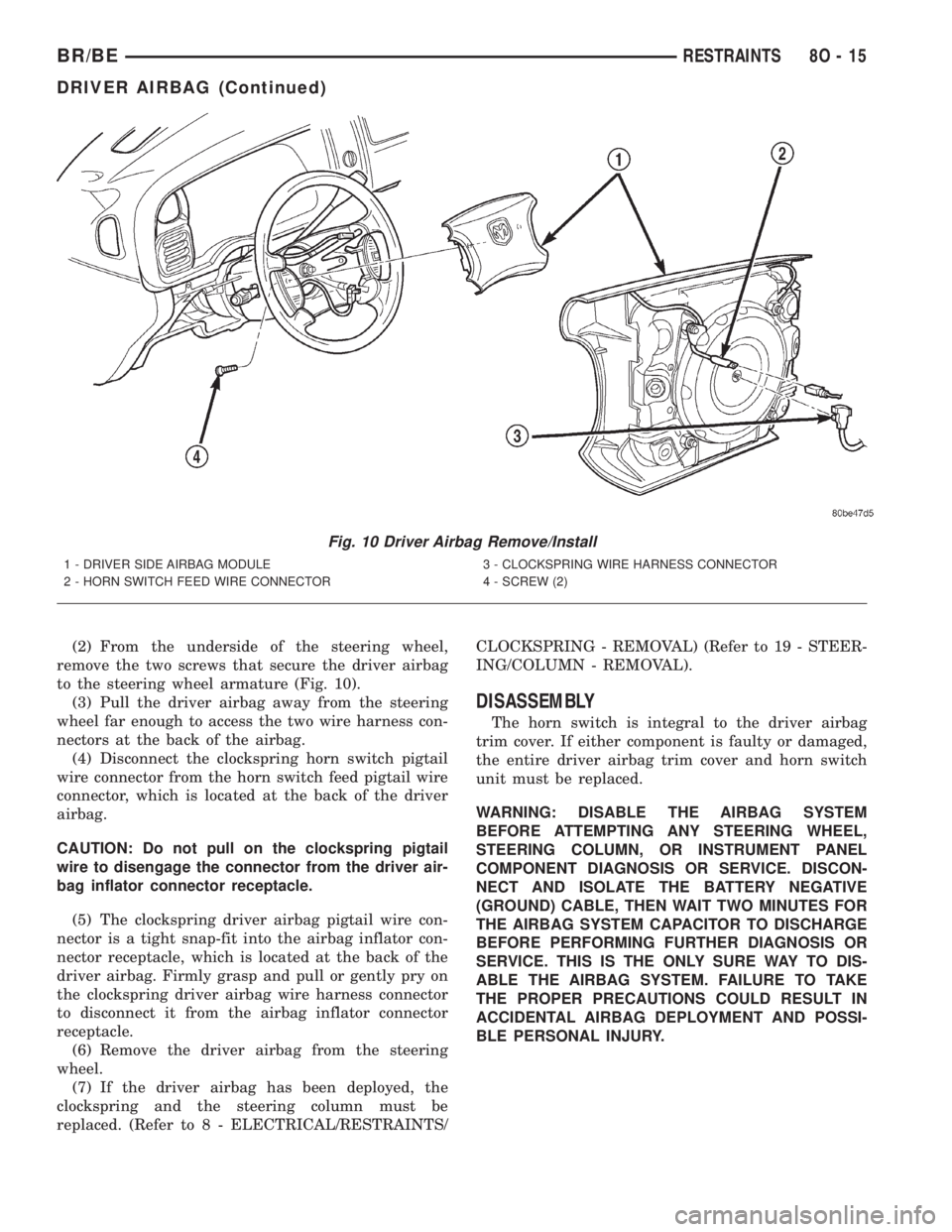
(2) From the underside of the steering wheel,
remove the two screws that secure the driver airbag
to the steering wheel armature (Fig. 10).
(3) Pull the driver airbag away from the steering
wheel far enough to access the two wire harness con-
nectors at the back of the airbag.
(4) Disconnect the clockspring horn switch pigtail
wire connector from the horn switch feed pigtail wire
connector, which is located at the back of the driver
airbag.
CAUTION: Do not pull on the clockspring pigtail
wire to disengage the connector from the driver air-
bag inflator connector receptacle.
(5) The clockspring driver airbag pigtail wire con-
nector is a tight snap-fit into the airbag inflator con-
nector receptacle, which is located at the back of the
driver airbag. Firmly grasp and pull or gently pry on
the clockspring driver airbag wire harness connector
to disconnect it from the airbag inflator connector
receptacle.
(6) Remove the driver airbag from the steering
wheel.
(7) If the driver airbag has been deployed, the
clockspring and the steering column must be
replaced. (Refer to 8 - ELECTRICAL/RESTRAINTS/CLOCKSPRING - REMOVAL) (Refer to 19 - STEER-
ING/COLUMN - REMOVAL).
DISASSEMBLY
The horn switch is integral to the driver airbag
trim cover. If either component is faulty or damaged,
the entire driver airbag trim cover and horn switch
unit must be replaced.
WARNING: DISABLE THE AIRBAG SYSTEM
BEFORE ATTEMPTING ANY STEERING WHEEL,
STEERING COLUMN, OR INSTRUMENT PANEL
COMPONENT DIAGNOSIS OR SERVICE. DISCON-
NECT AND ISOLATE THE BATTERY NEGATIVE
(GROUND) CABLE, THEN WAIT TWO MINUTES FOR
THE AIRBAG SYSTEM CAPACITOR TO DISCHARGE
BEFORE PERFORMING FURTHER DIAGNOSIS OR
SERVICE. THIS IS THE ONLY SURE WAY TO DIS-
ABLE THE AIRBAG SYSTEM. FAILURE TO TAKE
THE PROPER PRECAUTIONS COULD RESULT IN
ACCIDENTAL AIRBAG DEPLOYMENT AND POSSI-
BLE PERSONAL INJURY.
Fig. 10 Driver Airbag Remove/Install
1 - DRIVER SIDE AIRBAG MODULE
2 - HORN SWITCH FEED WIRE CONNECTOR3 - CLOCKSPRING WIRE HARNESS CONNECTOR
4 - SCREW (2)
BR/BERESTRAINTS 8O - 15
DRIVER AIRBAG (Continued)
Page 610 of 2255
the entire driver airbag trim cover and horn switch
unit must be replaced.
WARNING: DISABLE THE AIRBAG SYSTEM
BEFORE ATTEMPTING ANY STEERING WHEEL,
STEERING COLUMN, OR INSTRUMENT PANEL
COMPONENT DIAGNOSIS OR SERVICE. DISCON-
NECT AND ISOLATE THE BATTERY NEGATIVE
(GROUND) CABLE, THEN WAIT TWO MINUTES FOR
THE AIRBAG SYSTEM CAPACITOR TO DISCHARGE
BEFORE PERFORMING FURTHER DIAGNOSIS OR
SERVICE. THIS IS THE ONLY SURE WAY TO DIS-
ABLE THE AIRBAG SYSTEM. FAILURE TO TAKE
THE PROPER PRECAUTIONS COULD RESULT IN
ACCIDENTAL AIRBAG DEPLOYMENT AND POSSI-
BLE PERSONAL INJURY.
WARNING: THE HORN SWITCH IS INTEGRAL TO
THE DRIVER AIRBAG UNIT. SERVICE OF THIS UNIT
SHOULD BE PERFORMED ONLY BY
DAIMLERCHRYSLER-TRAINED AND AUTHORIZED
DEALER SERVICE TECHNICIANS. FAILURE TO
TAKE THE PROPER PRECAUTIONS OR TO FOL-
LOW THE PROPER PROCEDURES COULD RESULT
IN ACCIDENTAL, INCOMPLETE, OR IMPROPER AIR-
BAG DEPLOYMENT AND POSSIBLE OCCUPANT
INJURIES.
WARNING: USE EXTREME CARE TO PREVENT ANY
FOREIGN MATERIAL FROM ENTERING THE DRIVER
AIRBAG, OR BECOMING ENTRAPPED BETWEEN
THE DRIVER AIRBAG CUSHION AND THE DRIVER
AIRBAG TRIM COVER. FAILURE TO OBSERVE THIS
WARNING COULD RESULT IN OCCUPANT INJURIES
UPON AIRBAG DEPLOYMENT.
WARNING: THE DRIVER AIRBAG TRIM COVER
MUST NEVER BE PAINTED. REPLACEMENT TRIM
COVERS ARE SERVICED IN THE ORIGINAL COL-
ORS. PAINT MAY CHANGE THE WAY IN WHICH THE
MATERIAL OF THE TRIM COVER RESPONDS TO AN
AIRBAG DEPLOYMENT. FAILURE TO OBSERVE
THIS WARNING COULD RESULT IN OCCUPANT
INJURIES UPON AIRBAG DEPLOYMENT.
(1) Carefully position the driver airbag in the trim
cover. Be certain that the horn switch feed and
ground pigtail wires are not pinched between the air-
bag housing and the trim cover locking blocks.
(2) Engage the upper and lower trim cover locking
blocks with the lip of the driver airbag housing, then
engage the locking blocks on each side of the trim
cover with the lip of the housing. Be certain that
each of the locking blocks is fully engaged on the lip
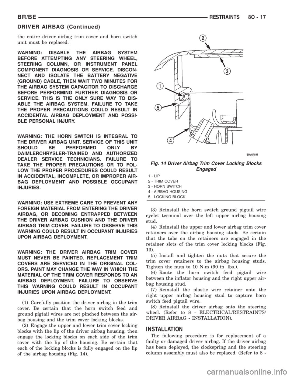
of the airbag housing (Fig. 14).(3) Reinstall the horn switch ground pigtail wire
eyelet terminal over the left upper airbag housing
stud.
(4) Reinstall the upper and lower airbag trim cover
retainers over the airbag housing studs. Be certain
that the tabs on the retainers are engaged in the
retainer slots of the trim cover locking blocks (Fig.
13).
(5) Install and tighten the nuts that secure the
trim cover retainers to the airbag housing studs.
Tighten the nuts to 10 N´m (90 in. lbs.).
(6) Route the horn switch feed pigtail wire
between the inflator housing and the right upper air-
bag housing stud.
(7) Reinstall the plastic wire retainer onto the
right upper airbag housing stud to capture horn
switch feed pigtail wire.
(8) Reinstall the driver airbag onto the steering
wheel. (Refer to 8 - ELECTRICAL/RESTRAINTS/
DRIVER AIRBAG - INSTALLATION).
INSTALLATION
The following procedure is for replacement of a
faulty or damaged driver airbag. If the driver airbag
has been deployed, the clockspring and the steering
column assembly must also be replaced. (Refer to 8 -
Fig. 14 Driver Airbag Trim Cover Locking Blocks
Engaged
1 - LIP
2 - TRIM COVER
3 - HORN SWITCH
4 - AIRBAG HOUSING
5 - LOCKING BLOCK
BR/BERESTRAINTS 8O - 17
DRIVER AIRBAG (Continued)
Page 1659 of 2255
(9) Install piston spring in retainer and on top of
piston. Concave side of spring faces downward
(toward piston).
(10) Install the spacer ring and wave spring into
the retainer. Be sure spring is completely seated in
retainer groove.
(11) Install pressure plate (Fig. 223). Ridged side
of plate faces downward (toward piston) and flat side
toward clutch pack.
(12) Install first clutch disc in retainer on top of
pressure plate. Then install a clutch plate followed
by a clutch disc until entire clutch pack is installed
(4 discs and 3 plates are required) (Fig. 223).
(13) Install the reaction plate.
(14) Install selective snap-ring. Be sure snap-ring
is fully seated in retainer groove.
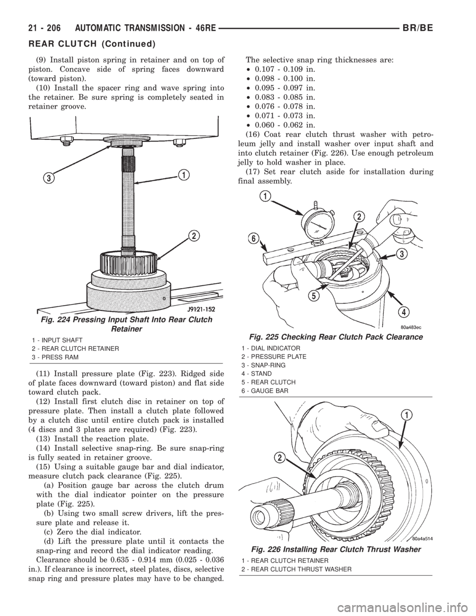
(15) Using a suitable gauge bar and dial indicator,
measure clutch pack clearance (Fig. 225).
(a) Position gauge bar across the clutch drum
with the dial indicator pointer on the pressure
plate (Fig. 225).
(b) Using two small screw drivers, lift the pres-
sure plate and release it.
(c) Zero the dial indicator.
(d) Lift the pressure plate until it contacts the
snap-ring and record the dial indicator reading.
Clearance should be 0.635 - 0.914 mm (0.025 - 0.036
in.). If clearance is incorrect, steel plates, discs, selective
snap ring and pressure plates may have to be changed.
The selective snap ring thicknesses are:
²0.107 - 0.109 in.
²0.098 - 0.100 in.
²0.095 - 0.097 in.
²0.083 - 0.085 in.
²0.076 - 0.078 in.
²0.071 - 0.073 in.
²0.060 - 0.062 in.
(16) Coat rear clutch thrust washer with petro-
leum jelly and install washer over input shaft and
into clutch retainer (Fig. 226). Use enough petroleum
jelly to hold washer in place.
(17) Set rear clutch aside for installation during
final assembly.
Fig. 224 Pressing Input Shaft Into Rear Clutch
Retainer
1 - INPUT SHAFT
2 - REAR CLUTCH RETAINER
3 - PRESS RAMFig. 225 Checking Rear Clutch Pack Clearance
1 - DIAL INDICATOR
2 - PRESSURE PLATE
3 - SNAP-RING
4-STAND
5 - REAR CLUTCH
6 - GAUGE BAR
Fig. 226 Installing Rear Clutch Thrust Washer
1 - REAR CLUTCH RETAINER
2 - REAR CLUTCH THRUST WASHER
21 - 206 AUTOMATIC TRANSMISSION - 46REBR/BE
REAR CLUTCH (Continued)
Page 1831 of 2255
(11) Install pressure plate (Fig. 223). Ridged side
of plate faces downward (toward piston) and flat side
toward clutch pack.
(12) Install first clutch disc in retainer on top of
pressure plate. Then install a clutch plate followed
by a clutch disc until entire clutch pack is installed
(4 discs and 3 plates are required) (Fig. 223).
(13) Install the reaction plate.
(14) Install selective snap-ring. Be sure snap-ring
is fully seated in retainer groove.
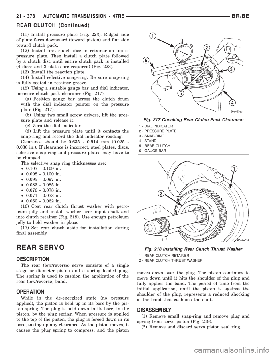
(15) Using a suitable gauge bar and dial indicator,
measure clutch pack clearance (Fig. 217).
(a) Position gauge bar across the clutch drum
with the dial indicator pointer on the pressure
plate (Fig. 217).
(b) Using two small screw drivers, lift the pres-
sure plate and release it.
(c) Zero the dial indicator.
(d) Lift the pressure plate until it contacts the
snap-ring and record the dial indicator reading.
Clearance should be 0.635 - 0.914 mm (0.025 -
0.036 in.). If clearance is incorrect, steel plates, discs,
selective snap ring and pressure plates may have to
be changed.
The selective snap ring thicknesses are:
²0.107 - 0.109 in.
²0.098 - 0.100 in.
²0.095 - 0.097 in.
²0.083 - 0.085 in.
²0.076 - 0.078 in.
²0.071 - 0.073 in.
²0.060 - 0.062 in.
(16) Coat rear clutch thrust washer with petro-
leum jelly and install washer over input shaft and
into clutch retainer (Fig. 218). Use enough petroleum
jelly to hold washer in place.
(17) Set rear clutch aside for installation during
final assembly.
REAR SERVO
DESCRIPTION
The rear (low/reverse) servo consists of a single
stage or diameter piston and a spring loaded plug.
The spring is used to cushion the application of the
rear (low/reverse) band.
OPERATION
While in the de-energized state (no pressure
applied), the piston is held up in its bore by the pis-
ton spring. The plug is held down in its bore, in the
piston, by the plug spring. When pressure is applied
to the top of the piston, the plug is forced down in its
bore, taking up any clearance. As the piston moves, it
causes the plug spring to compress, and the pistonmoves down over the plug. The piston continues to
move down until it hits the shoulder of the plug and
fully applies the band. The period of time from the
initial application, until the piston is against the
shoulder of the plug, represents a reduced shocking
of the band that cushions the shift.
DISASSEMBLY
(1) Remove small snap-ring and remove plug and
spring from servo piston (Fig. 219).
(2) Remove and discard servo piston seal ring.
Fig. 217 Checking Rear Clutch Pack Clearance
1 - DIAL INDICATOR
2 - PRESSURE PLATE
3 - SNAP-RING
4-STAND
5 - REAR CLUTCH
6 - GAUGE BAR
Fig. 218 Installing Rear Clutch Thrust Washer
1 - REAR CLUTCH RETAINER
2 - REAR CLUTCH THRUST WASHER
21 - 378 AUTOMATIC TRANSMISSION - 47REBR/BE
REAR CLUTCH (Continued)
Page 1956 of 2255
TIRES/WHEELS
TABLE OF CONTENTS
page page
TIRES/WHEELS
DIAGNOSIS AND TESTING - TIRE AND
WHEEL RUNOUT......................1
STANDARD PROCEDURE
STANDARD PROCEDURE -
TIRE ROTATION.......................2
STANDARD PROCEDURE - MATCH
MOUNTING...........................3
STANDARD PROCEDURE - TIRE AND
WHEEL BALANCE......................4
TIRES
DESCRIPTION
DESCRIPTION - SPARE TIRE - TEMPORARY...6
DESCRIPTION - TIRES..................6
DESCRIPTION - RADIAL-PLY TIRES........6
DESCRIPTION - TIRE PRESSURE FOR
HIGH SPEEDS.........................7
DESCRIPTION - REPLACEMENT TIRES.....7
DESCRIPTION - TIRE INFLATION
PRESSURES..........................7
DIAGNOSIS AND TESTING
DIAGNOSIS AND TESTING - PRESSURE
GAUGES.............................8
DIAGNOSIS AND TESTING - TREAD WEAR
INDICATORS..........................8
DIAGNOSIS AND TESTING - TIRE WEAR
PATTERNS...........................8DIAGNOSIS AND TESTING - TIRE NOISE
OR VIBRATION........................9
STANDARD PROCEDURE - REPAIRING
LEAKS...............................9
SPECIFICATIONS
TIRE REVOLUTIONS PER MILE...........9
SPARE TIRE
DESCRIPTION.........................10
WHEELS
DESCRIPTION.........................10
OPERATION...........................10
DIAGNOSIS AND TESTING
WHEEL INSPECTION..................11
STANDARD PROCEDURE - DUAL REAR
WHEEL INSTALLATION.................11
SPECIFICATIONS
TORQUE CHART......................11
STUDS
REMOVAL.............................12
INSTALLATION.........................12
WHEEL COVER
REMOVAL.............................12
INSTALLATION
INSTALLATION - REAR.................12
INSTALLATION - FRONT................12
TIRES/WHEELS
DIAGNOSIS AND TESTING - TIRE AND WHEEL
RUNOUT
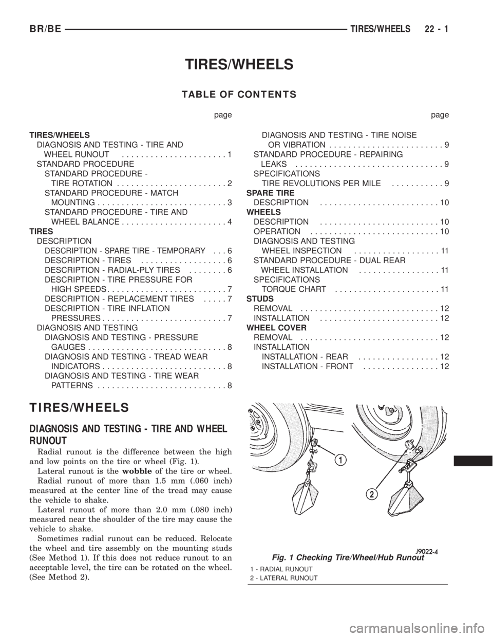
Radial runout is the difference between the high
and low points on the tire or wheel (Fig. 1).
Lateral runout is thewobbleof the tire or wheel.
Radial runout of more than 1.5 mm (.060 inch)
measured at the center line of the tread may cause
the vehicle to shake.
Lateral runout of more than 2.0 mm (.080 inch)
measured near the shoulder of the tire may cause the
vehicle to shake.
Sometimes radial runout can be reduced. Relocate
the wheel and tire assembly on the mounting studs
(See Method 1). If this does not reduce runout to an
acceptable level, the tire can be rotated on the wheel.
(See Method 2).
Fig. 1 Checking Tire/Wheel/Hub Runout
1 - RADIAL RUNOUT
2 - LATERAL RUNOUT
BR/BETIRES/WHEELS 22 - 1