2002 DODGE RAM torque
[x] Cancel search: torquePage 627 of 2255
DIAGNOSIS AND TESTING - ROAD TEST
Perform a vehicle road test to verify reports of
speed control system malfunction. The road test
should include attention to the speedometer.
If a road test verifies a system problem and the
speedometer operates properly, check for:
²A Diagnostic Trouble Code (DTC). If a DTC
exists, conduct tests per the Powertrain Diagnostic
Procedures service manual.
²A misadjusted brake (stop) lamp switch. This
could also cause an intermittent problem.
²Loose, damaged or corroded electrical connec-
tions at the servo. Corrosion should be removed from
electrical terminals and a light coating of Mopart
MultiPurpose Grease, or equivalent, applied.²Leaking vacuum reservoir.
²Loose or leaking vacuum hoses or connections.
²Defective one-way vacuum check valve.
²Secure attachment of both ends of the speed con-
trol servo cable.
²Smooth operation of throttle linkage and throttle
body air valve.
²Failed speed control servo. Do the servo vacuum
test.
CAUTION: When test probing for voltage or conti-
nuity at electrical connectors, care must be taken
not to damage connector, terminals or seals. If
these components are damaged, intermittent or
complete system failure may occur.
SPECIFICATIONS
TORQUE - SPEED CONTROL SYSTEM
DESCRIPTION N´m Ft. Lbs. In. Lbs.
Servo Mounting Bracket
Nuts8.5 - 75
Switch Module Mounting
Screws3-26
Vacuum Reservoir
Mounting Screws2.2 -
20
CABLE
DESCRIPTION
The speed control servo cable is connected between
the speed control vacuum servo diaphragm and the
throttle body control linkage.
OPERATION
This cable causes the throttle control linkage to
open or close the throttle valve in response to move-
ment of the vacuum servo diaphragm.
REMOVAL
REMOVAL - GAS ENGINES
(1) Disconnect negative battery cable at battery.
(2) Remove air cleaner (all except 8.0L V-10
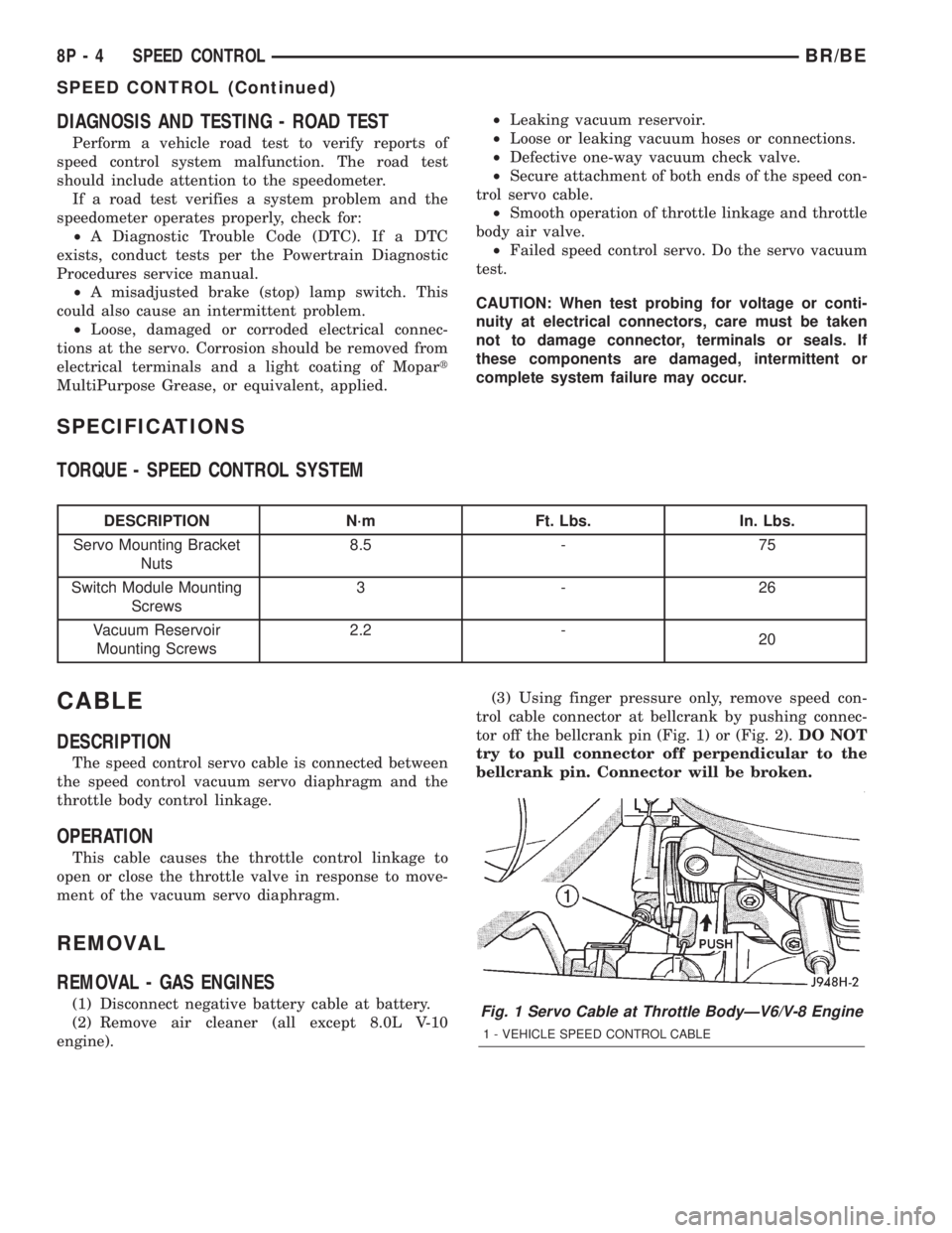
engine).(3) Using finger pressure only, remove speed con-
trol cable connector at bellcrank by pushing connec-
tor off the bellcrank pin (Fig. 1) or (Fig. 2).DO NOT
try to pull connector off perpendicular to the
bellcrank pin. Connector will be broken.Fig. 1 Servo Cable at Throttle BodyÐV6/V-8 Engine
1 - VEHICLE SPEED CONTROL CABLE
8P - 4 SPEED CONTROLBR/BE
SPEED CONTROL (Continued)
Page 634 of 2255
INSTALLATION
INSTALLATION
V-8 ENGINE
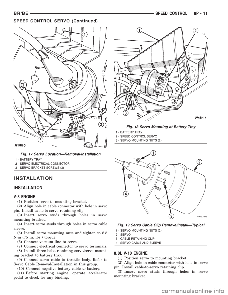
(1) Position servo to mounting bracket.
(2) Align hole in cable connector with hole in servo
pin. Install cable-to-servo retaining clip.
(3) Insert servo studs through holes in servo
mounting bracket.
(4) Insert servo studs through holes in servo cable
sleeve.
(5) Install servo mounting nuts and tighten to 8.5
N´m (75 in. lbs.) torque.
(6) Connect vacuum line to servo.
(7) Connect electrical connector to servo terminals.
(8) Install three bolts retaining servo/servo mount-
ing bracket to battery tray.
(9) Connect servo cable to throttle body. Refer to
Servo Cable Removal/Installation in this group.
(10) Connect negative battery cable to battery.
(11) Before starting engine, operate accelerator
pedal to check for any binding.
8.0L V-10 ENGINE
(1) Position servo to mounting bracket.
(2) Align hole in cable connector with hole in servo
pin. Install cable-to-servo retaining clip.
(3) Insert servo studs through holes in servo
mounting bracket.
Fig. 17 Servo LocationÐRemoval/Installation
1 - BATTERY TRAY
2 - SERVO ELECTRICAL CONNECTOR
3 - SERVO BRACKET SCREWS (3)
Fig. 18 Servo Mounting at Battery Tray
1 - BATTERY TRAY
2 - SPEED CONTROL SERVO
3 - SERVO MOUNTING NUTS (2)
Fig. 19 Servo Cable Clip Remove/InstallÐTypical
1 - SERVO MOUNTING NUTS (2)
2 - SERVO
3 - CABLE RETAINING CLIP
4 - SERVO CABLE AND SLEEVE
BR/BESPEED CONTROL 8P - 11
SPEED CONTROL SERVO (Continued)
Page 635 of 2255
(4) Insert servo studs through holes in servo cable
sleeve.
(5) Install servo mounting nuts and tighten to 8.5
N´m (75 in. lbs.) torque.
(6) Connect vacuum line to servo.
(7) Connect electrical connector to servo terminals.
(8) Connect servo cable to throttle body. Refer to
Servo Cable Removal/Installation in this group.
(9) Install battery tray. Tighten all battery tray
mounting hardware to 16 N´m (140 in. lbs.) torque.
(10) Position battery into battery tray.
(11) If equipped, install battery heat shield.
(12) Install battery holddown clamp. Tighten bolt
to 4 N´m (35 in. lbs.) torque.
(13) Connect positive battery cable to battery.
(14) Connect negative battery cable to battery.
(15) Before starting engine, operate accelerator
pedal to check for any binding.
INSTALLATION - DIESEL WITH AUTO. TRANS.
(1) Position servo to mounting bracket.
(2) Align hole in cable connector with hole in servo
pin. Install cable-to-servo retaining clip.
(3) Insert servo studs through holes in servo
mounting bracket.
(4) Insert servo studs through holes in servo cable
sleeve.
(5) Install servo mounting nuts and tighten to 8.5
N´m (75 in. lbs.) torque.
(6) Connect vacuum line to servo.
(7) Connect electrical connector to servo terminals.
(8) Connect servo cable to throttle lever by push-
ing cable connector rearward onto lever pin while
holding lever forward.
(9) Install battery tray. Tighten all battery tray
mounting hardware to 16 N´m (140 in. lbs.) torque.
(10) Position battery into battery tray.
(11) If equipped, install battery heat shield.
(12) Install battery holddown clamp. Tighten bolt
to 4 N´m (35 in. lbs.) torque.
(13) Connect positive battery cable to battery.
(14) Connect negative battery cables to both bat-
teries.
(15) Before starting engine, operate accelerator
pedal to check for any binding.
(16) Install cable/lever cover.
SWITCH
DESCRIPTION
Gas Engines and Diesel With Auto. Trans.
There are two separate switch pods that operate
the speed control system. The steering-wheel-
mounted switches use multiplexed circuits to provideinputs to the Powertrain Control Module (PCM) for
ON, OFF, RESUME, ACCELERATE, SET, DECEL
and CANCEL modes. Refer to the owner's manual for
more information on speed control switch functions
and setting procedures.
The individual switches cannot be repaired. If one
switch fails, the entire switch module must be
replaced.
Diesel With Manual Trans.
There are two separate switch pods that operate
the speed control system. The steering-wheel-
mounted switches use multiplexed circuits to provide
inputs to the Engine Control Module (ECM) for ON,
OFF, RESUME, ACCELERATE, SET, DECEL and
CANCEL modes. Refer to the owner's manual for
more information on speed control switch functions
and setting procedures.
The individual switches cannot be repaired. If one
switch fails, the entire switch module must be
replaced.
OPERATION
Gas Engines and Diesel With Auto. Trans.
When speed control is selected by depressing the
ON, OFF switch, the Powertrain Control Module
(PCM) allows a set speed to be stored in its RAM for
speed control. To store a set speed, depress the SET
switch while the vehicle is moving at a speed
between approximately 35 and 85 mph. In order for
the speed control to engage, the brakes cannot be
applied, nor can the gear selector be indicating the
transmission is in Park or Neutral.
The speed control can be disengaged manually by:
²Stepping on the brake pedal.
²Depressing the OFF switch.
²Depressing the CANCEL switch.
The speed control can be disengaged also by any of
the following conditions:
²An indication of Park or Neutral.
²The vehicle speed signal increases at a rate of
10 mph per second (indicates that the co-efficient of
friction between the road surface and tires is
extremely low).
²Depressing the clutch pedal.
²Excessive engine rpm (indicates that the trans-
mission may be in a low gear).
²The vehicle speed signal decreases at a rate of
10 mph per second (indicates that the vehicle may
have decelerated at an extremely high rate).
²If the actual speed is not within 20 mph of the
set speed.
The previous disengagement conditions are pro-
grammed for added safety.
8P - 12 SPEED CONTROLBR/BE
SPEED CONTROL SERVO (Continued)
Page 637 of 2255
INSTALLATION
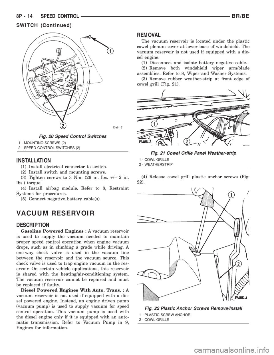
(1) Install electrical connector to switch.
(2) Install switch and mounting screws.
(3) Tighten screws to 3 N´m (26 in. lbs. +/± 2 in.
lbs.) torque.
(4) Install airbag module. Refer to 8, Restraint
Systems for procedures.
(5) Connect negative battery cable(s).
VACUUM RESERVOIR
DESCRIPTION
Gasoline Powered Engines :A vacuum reservoir
is used to supply the vacuum needed to maintain
proper speed control operation when engine vacuum
drops, such as in climbing a grade while driving. A
one-way check valve is used in the vacuum line
between the reservoir and the vacuum source. This
check valve is used to trap engine vacuum in the res-
ervoir. On certain vehicle applications, this reservoir
is shared with the heating/air-conditioning system.
The vacuum reservoir cannot be repaired and must
be replaced if faulty.
Diesel Powered Engines With Auto. Trans. :A
vacuum reservoir is not used if equipped with a die-
sel powered engine. Instead, an engine driven pump
(vacuum pump) is used to supply vacuum for speed
control operation. This vacuum pump is used with
the diesel engine only if it is equipped with an auto-
matic transmission. Refer to Vacuum Pump in 9,
Engines for information.
REMOVAL
The vacuum reservoir is located under the plastic
cowel plenum cover at lower base of windshield. The
vacuum reservoir is not used if equipped with a die-
sel engine.
(1) Disconnect and isolate battery negative cable.
(2) Remove both windshield wiper arm/blade
assemblies. Refer to 8, Wiper and Washer Systems.
(3) Remove rubber weather-strip at front edge of
cowel grill (Fig. 21).
(4) Release cowel grill plastic anchor screws (Fig.
22).
Fig. 20 Speed Control Switches
1 - MOUNTING SCREWS (2)
2 - SPEED CONTROL SWITCHES (2)
Fig. 21 Cowel Grille Panel Weather-strip
1 - COWL GRILLE
2 - WEATHERSTRIP
Fig. 22 Plastic Anchor Screws Remove/Install
1 - PLASTIC SCREW ANCHOR
2 - COWL GRILLE
8P - 14 SPEED CONTROLBR/BE
SWITCH (Continued)
Page 638 of 2255
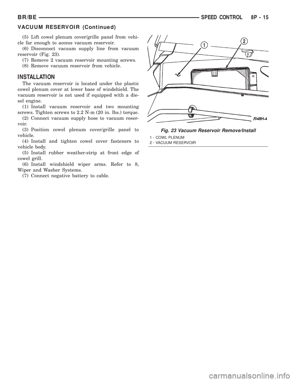
(5) Lift cowel plenum cover/grille panel from vehi-
cle far enough to access vacuum reservoir.
(6) Disconnect vacuum supply line from vacuum
reservoir (Fig. 23).
(7) Remove 2 vacuum reservoir mounting screws.
(8) Remove vacuum reservoir from vehicle.
INSTALLATION
The vacuum reservoir is located under the plastic
cowel plenum cover at lower base of windshield. The
vacuum reservoir is not used if equipped with a die-
sel engine.
(1) Install vacuum reservoir and two mounting
screws. Tighten screws to 2.2 N´m (20 in. lbs.) torque.
(2) Connect vacuum supply hose to vacuum reser-
voir.
(3) Position cowel plenum cover/grille panel to
vehicle.
(4) Install and tighten cowel cover fasteners to
vehicle body.
(5) Install rubber weather-strip at front edge of
cowel grill.
(6) Install windshield wiper arms. Refer to 8,
Wiper and Washer Systems.
(7) Connect negative battery to cable.
Fig. 23 Vacuum Reservoir Remove/Install
1 - COWL PLENUM
2 - VACUUM RESERVOIR
BR/BESPEED CONTROL 8P - 15
VACUUM RESERVOIR (Continued)
Page 1006 of 2255
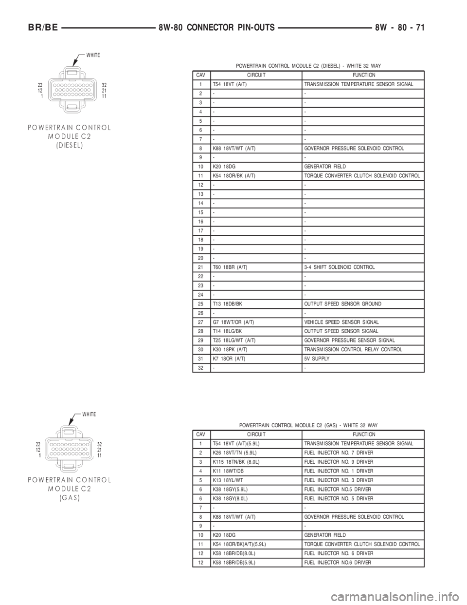
POWERTRAIN CONTROL MODULE C2 (DIESEL) - WHITE 32 WAY
CAV CIRCUIT FUNCTION
1 T54 18VT (A/T) TRANSMISSION TEMPERATURE SENSOR SIGNAL
2- -
3- -
4- -
5- -
6- -
7- -
8 K88 18VT/WT (A/T) GOVERNOR PRESSURE SOLENOID CONTROL
9- -
10 K20 18DG GENERATOR FIELD
11 K54 18OR/BK (A/T) TORQUE CONVERTER CLUTCH SOLENOID CONTROL
12 - -
13 - -
14 - -
15 - -
16 - -
17 - -
18 - -
19 - -
20 - -
21 T60 18BR (A/T) 3-4 SHIFT SOLENOID CONTROL
22 - -
23 - -
24 - -
25 T13 18DB/BK OUTPUT SPEED SENSOR GROUND
26 - -
27 G7 18WT/OR (A/T) VEHICLE SPEED SENSOR SIGNAL
28 T14 18LG/BK OUTPUT SPEED SENSOR SIGNAL
29 T25 18LG/WT (A/T) GOVERNOR PRESSURE SENSOR SIGNAL
30 K30 18PK (A/T) TRANSMISSION CONTROL RELAY CONTROL
31 K7 18OR (A/T) 5V SUPPLY
32 - -
POWERTRAIN CONTROL MODULE C2 (GAS) - WHITE 32 WAY
CAV CIRCUIT FUNCTION
1 T54 18VT (A/T)(5.9L) TRANSMISSION TEMPERATURE SENSOR SIGNAL
2 K26 18VT/TN (5.9L) FUEL INJECTOR NO. 7 DRIVER
3 K115 18TN/BK (8.0L) FUEL INJECTOR NO. 9 DRIVER
4 K11 18WT/DB FUEL INJECTOR NO. 1 DRIVER
5 K13 18YL/WT FUEL INJECTOR NO. 3 DRIVER
6 K38 18GY(5.9L) FUEL INJECTOR NO.5 DRIVER
6 K38 18GY(8.0L) FUEL INJECTOR NO. 5 DRIVER
7- -
8 K88 18VT/WT (A/T) GOVERNOR PRESSURE SOLENOID CONTROL
9- -
10 K20 18DG GENERATOR FIELD
11 K54 18OR/BK(A/T)(5.9L) TORQUE CONVERTER CLUTCH SOLENOID CONTROL
12 K58 18BR/DB(8.0L) FUEL INJECTOR NO. 6 DRIVER
12 K58 18BR/DB(5.9L) FUEL INJECTOR NO.6 DRIVER
BR/BE8W-80 CONNECTOR PIN-OUTS 8W - 80 - 71
Page 1015 of 2255
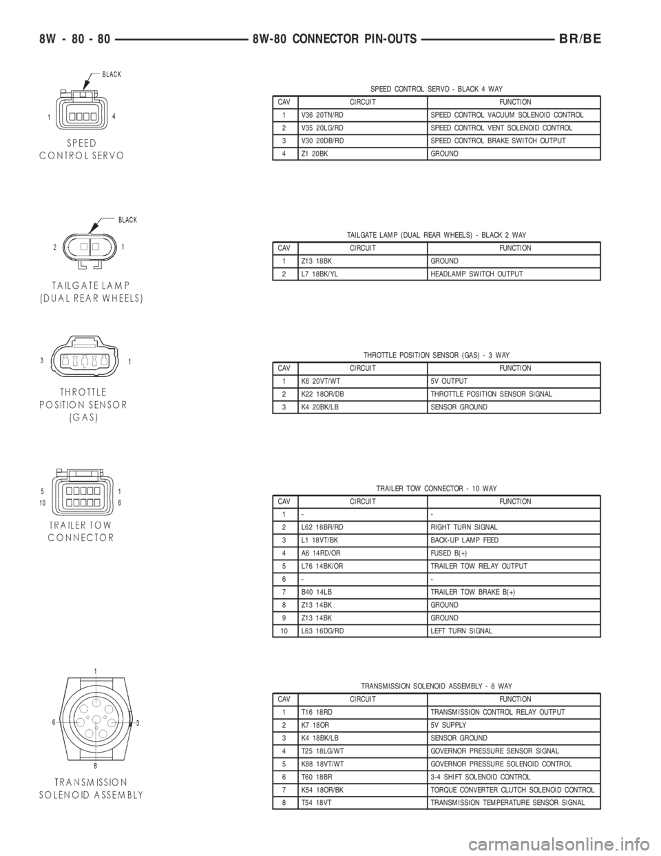
SPEED CONTROL SERVO - BLACK 4 WAY
CAV CIRCUIT FUNCTION
1 V36 20TN/RD SPEED CONTROL VACUUM SOLENOID CONTROL
2 V35 20LG/RD SPEED CONTROL VENT SOLENOID CONTROL
3 V30 20DB/RD SPEED CONTROL BRAKE SWITCH OUTPUT
4 Z1 20BK GROUND
TAILGATE LAMP (DUAL REAR WHEELS) - BLACK 2 WAY
CAV CIRCUIT FUNCTION
1 Z13 18BK GROUND
2 L7 18BK/YL HEADLAMP SWITCH OUTPUT
THROTTLE POSITION SENSOR (GAS)-3WAY
CAV CIRCUIT FUNCTION
1 K6 20VT/WT 5V OUTPUT
2 K22 18OR/DB THROTTLE POSITION SENSOR SIGNAL
3 K4 20BK/LB SENSOR GROUND
TRAILER TOW CONNECTOR - 10 WAY
CAV CIRCUIT FUNCTION
1- -
2 L62 16BR/RD RIGHT TURN SIGNAL
3 L1 18VT/BK BACK-UP LAMP FEED
4 A6 14RD/OR FUSED B(+)
5 L76 14BK/OR TRAILER TOW RELAY OUTPUT
6- -
7 B40 14LB TRAILER TOW BRAKE B(+)
8 Z13 14BK GROUND
9 Z13 14BK GROUND
10 L63 16DG/RD LEFT TURN SIGNAL
TRANSMISSION SOLENOID ASSEMBLY-8WAY
CAV CIRCUIT FUNCTION
1 T16 18RD TRANSMISSION CONTROL RELAY OUTPUT
2 K7 18OR 5V SUPPLY
3 K4 18BK/LB SENSOR GROUND
4 T25 18LG/WT GOVERNOR PRESSURE SENSOR SIGNAL
5 K88 18VT/WT GOVERNOR PRESSURE SOLENOID CONTROL
6 T60 18BR 3-4 SHIFT SOLENOID CONTROL
7 K54 18OR/BK TORQUE CONVERTER CLUTCH SOLENOID CONTROL
8 T54 18VT TRANSMISSION TEMPERATURE SENSOR SIGNAL
8W - 80 - 80 8W-80 CONNECTOR PIN-OUTSBR/BE
Page 1064 of 2255
to service. Refer toCharging Systemin the index of
this service manual for the charging system diagnos-
tic procedures.
(1) Position the generator cartridge fuse onto the
two B(+) terminal stud bus bars within the PDC.
(2) Install and tighten the two screws that secure
the generator cartridge fuse to the two B(+) terminal
stud bus bars within the PDC. Tighten the screws to
3.4 N´m (30 in. lbs.).Be certain that both screws
are tightened to the proper torque value.
(3) Install and latch the cover onto the PDC.
(4) Reconnect the battery negative cable.
IOD FUSE
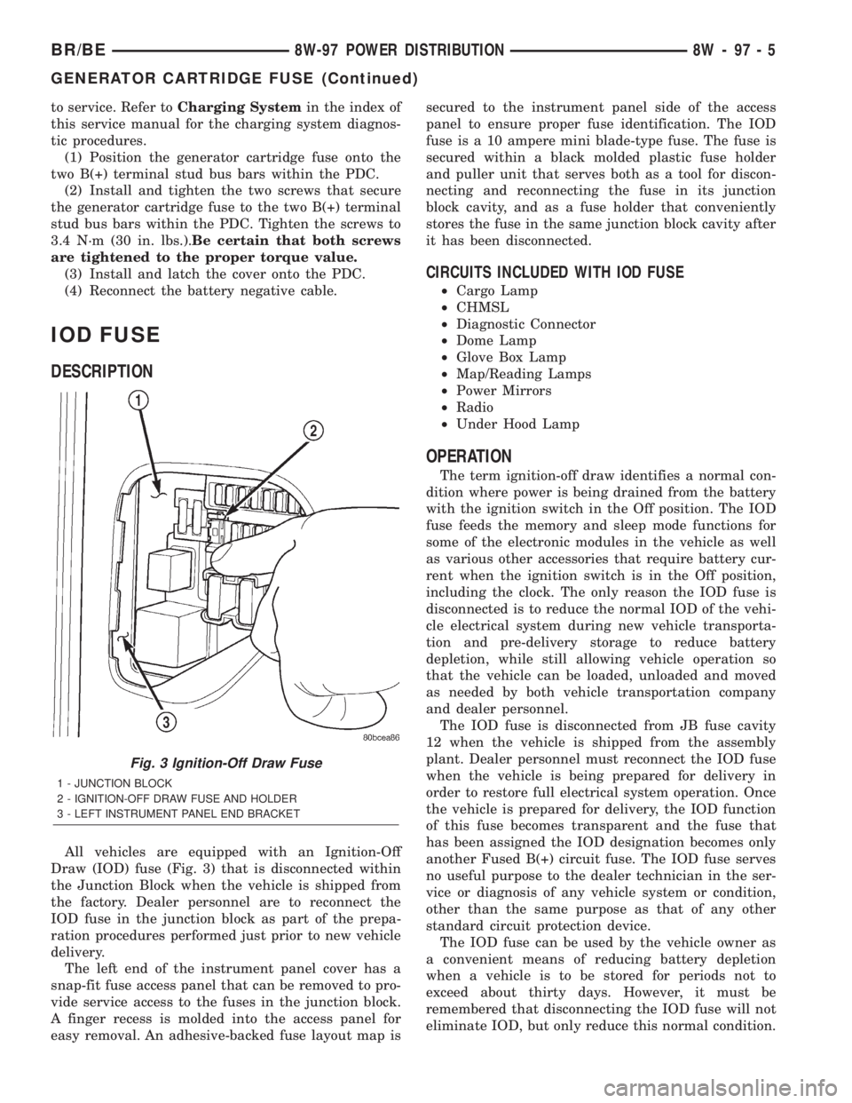
DESCRIPTION
All vehicles are equipped with an Ignition-Off
Draw (IOD) fuse (Fig. 3) that is disconnected within
the Junction Block when the vehicle is shipped from
the factory. Dealer personnel are to reconnect the
IOD fuse in the junction block as part of the prepa-
ration procedures performed just prior to new vehicle
delivery.
The left end of the instrument panel cover has a
snap-fit fuse access panel that can be removed to pro-
vide service access to the fuses in the junction block.
A finger recess is molded into the access panel for
easy removal. An adhesive-backed fuse layout map issecured to the instrument panel side of the access
panel to ensure proper fuse identification. The IOD
fuse is a 10 ampere mini blade-type fuse. The fuse is
secured within a black molded plastic fuse holder
and puller unit that serves both as a tool for discon-
necting and reconnecting the fuse in its junction
block cavity, and as a fuse holder that conveniently
stores the fuse in the same junction block cavity after
it has been disconnected.
CIRCUITS INCLUDED WITH IOD FUSE
²Cargo Lamp
²CHMSL
²Diagnostic Connector
²Dome Lamp
²Glove Box Lamp
²Map/Reading Lamps
²Power Mirrors
²Radio
²Under Hood Lamp
OPERATION
The term ignition-off draw identifies a normal con-
dition where power is being drained from the battery
with the ignition switch in the Off position. The IOD
fuse feeds the memory and sleep mode functions for
some of the electronic modules in the vehicle as well
as various other accessories that require battery cur-
rent when the ignition switch is in the Off position,
including the clock. The only reason the IOD fuse is
disconnected is to reduce the normal IOD of the vehi-
cle electrical system during new vehicle transporta-
tion and pre-delivery storage to reduce battery
depletion, while still allowing vehicle operation so
that the vehicle can be loaded, unloaded and moved
as needed by both vehicle transportation company
and dealer personnel.
The IOD fuse is disconnected from JB fuse cavity
12 when the vehicle is shipped from the assembly
plant. Dealer personnel must reconnect the IOD fuse
when the vehicle is being prepared for delivery in
order to restore full electrical system operation. Once
the vehicle is prepared for delivery, the IOD function
of this fuse becomes transparent and the fuse that
has been assigned the IOD designation becomes only
another Fused B(+) circuit fuse. The IOD fuse serves
no useful purpose to the dealer technician in the ser-
vice or diagnosis of any vehicle system or condition,
other than the same purpose as that of any other
standard circuit protection device.
The IOD fuse can be used by the vehicle owner as
a convenient means of reducing battery depletion
when a vehicle is to be stored for periods not to
exceed about thirty days. However, it must be
remembered that disconnecting the IOD fuse will not
eliminate IOD, but only reduce this normal condition.
Fig. 3 Ignition-Off Draw Fuse
1 - JUNCTION BLOCK
2 - IGNITION-OFF DRAW FUSE AND HOLDER
3 - LEFT INSTRUMENT PANEL END BRACKET
BR/BE8W-97 POWER DISTRIBUTION 8W - 97 - 5
GENERATOR CARTRIDGE FUSE (Continued)