2002 DODGE RAM torque
[x] Cancel search: torquePage 467 of 2255
(4) Install mounting bolt and tighten to 20 Nm (15
ft. lbs.) torque.
(5) Install electrical connector to CMP.
(6) Connect both negative cables to both batteries.
INSTALLATION - 5.9L
The camshaft position sensor is located in the dis-
tributor (Fig. 11).
(1) Install camshaft position sensor to distributor.
Align sensor into notch on distributor housing.
(2) Connect wiring harness.
(3) Install rotor.
(4) Install distributor cap. Tighten mounting
screws.
(5) Install air cleaner assembly.
INSTALLATION - 8.0L
If Replacing Old Sensor With Original
The camshaft position sensor is located on the tim-
ing chain case/cover on the left-front side of the
engine (Fig. 12).
When installing a used camshaft position sensor,
the sensor depth must be adjusted to prevent contact
with the camshaft gear (sprocket).
(1) Observe the face of the sensor. If any of the
original rib material remains (Fig. 13), it must be cut
down flush to the face of the sensor with a razor
knife. Remove only enough of the rib material until
the face of the sensor is flat. Do not remove more
material than necessary as damage to sensor may
result. Due to a high magnetic field and possible elec-
trical damage to the sensor, never use an electric
grinder to remove material from sensor.
(2) From the parts department, obtain a peel-and-
stick paper spacer (Fig. 13). These special paper
spacers are of a certain thickness and are to be used
as a tool to set sensor depth.
(3) Clean the face of sensor and apply paper
spacer (Fig. 13).
(4) Apply a small amount of engine oil to the sen-
sor o-ring (Fig. 14).
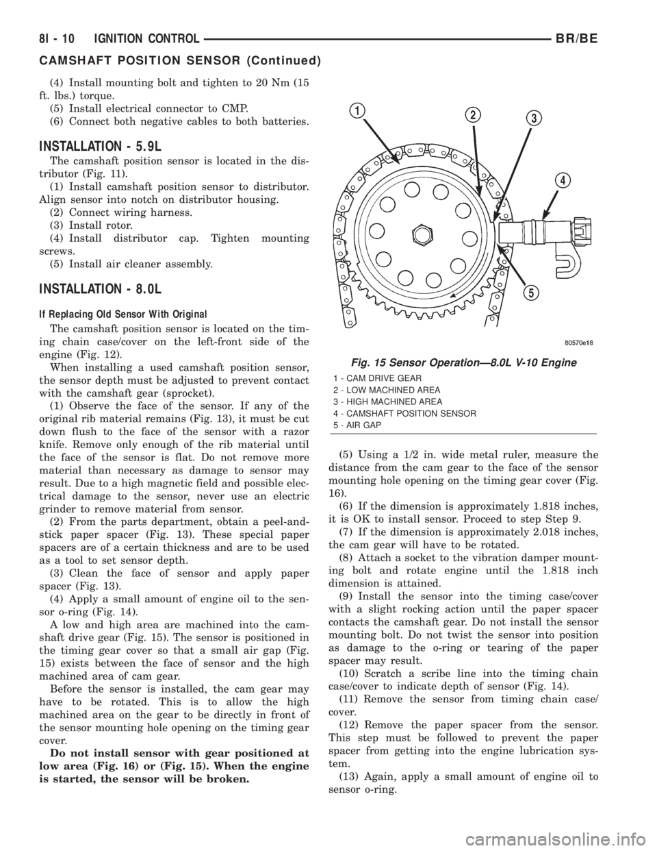
A low and high area are machined into the cam-
shaft drive gear (Fig. 15). The sensor is positioned in
the timing gear cover so that a small air gap (Fig.
15) exists between the face of sensor and the high
machined area of cam gear.
Before the sensor is installed, the cam gear may
have to be rotated. This is to allow the high
machined area on the gear to be directly in front of
the sensor mounting hole opening on the timing gear
cover.
Do not install sensor with gear positioned at
low area (Fig. 16) or (Fig. 15). When the engine
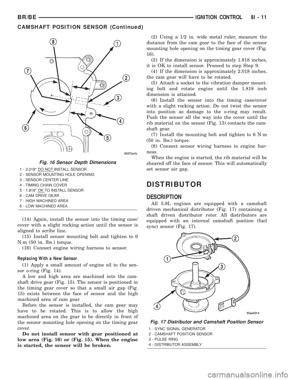
is started, the sensor will be broken.(5) Using a 1/2 in. wide metal ruler, measure the
distance from the cam gear to the face of the sensor
mounting hole opening on the timing gear cover (Fig.
16).
(6) If the dimension is approximately 1.818 inches,
it is OK to install sensor. Proceed to step Step 9.
(7) If the dimension is approximately 2.018 inches,
the cam gear will have to be rotated.
(8) Attach a socket to the vibration damper mount-
ing bolt and rotate engine until the 1.818 inch
dimension is attained.
(9) Install the sensor into the timing case/cover
with a slight rocking action until the paper spacer
contacts the camshaft gear. Do not install the sensor
mounting bolt. Do not twist the sensor into position
as damage to the o-ring or tearing of the paper
spacer may result.
(10) Scratch a scribe line into the timing chain
case/cover to indicate depth of sensor (Fig. 14).
(11) Remove the sensor from timing chain case/
cover.
(12) Remove the paper spacer from the sensor.
This step must be followed to prevent the paper
spacer from getting into the engine lubrication sys-
tem.
(13) Again, apply a small amount of engine oil to
sensor o-ring.
Fig. 15 Sensor OperationÐ8.0L V-10 Engine
1 - CAM DRIVE GEAR
2 - LOW MACHINED AREA
3 - HIGH MACHINED AREA
4 - CAMSHAFT POSITION SENSOR
5 - AIR GAP
8I - 10 IGNITION CONTROLBR/BE
CAMSHAFT POSITION SENSOR (Continued)
Page 468 of 2255
(14) Again, install the sensor into the timing case/
cover with a slight rocking action until the sensor is
aligned to scribe line.
(15) Install sensor mounting bolt and tighten to 6
N´m (50 in. lbs.) torque.
(16) Connect engine wiring harness to sensor.
Replacing With a New Sensor
(1) Apply a small amount of engine oil to the sen-
sor o-ring (Fig. 14).
A low and high area are machined into the cam-
shaft drive gear (Fig. 15). The sensor is positioned in
the timing gear cover so that a small air gap (Fig.
15) exists between the face of sensor and the high
machined area of cam gear.
Before the sensor is installed, the cam gear may
have to be rotated. This is to allow the high
machined area on the gear to be directly in front of
the sensor mounting hole opening on the timing gear
cover.
Do not install sensor with gear positioned at
low area (Fig. 16) or (Fig. 15). When the engine
is started, the sensor will be broken.(2) Using a 1/2 in. wide metal ruler, measure the
distance from the cam gear to the face of the sensor
mounting hole opening on the timing gear cover (Fig.
16).
(3) If the dimension is approximately 1.818 inches,
it is OK to install sensor. Proceed to step Step 9.
(4) If the dimension is approximately 2.018 inches,
the cam gear will have to be rotated.
(5) Attach a socket to the vibration damper mount-
ing bolt and rotate engine until the 1.818 inch
dimension is attained.
(6) Install the sensor into the timing case/cover
with a slight rocking action. Do not twist the sensor
into position as damage to the o-ring may result.
Push the sensor all the way into the cover until the
rib material on the sensor (Fig. 13) contacts the cam-
shaft gear.
(7) Install the mounting bolt and tighten to 6 N´m
(50 in. lbs.) torque.
(8) Connect sensor wiring harness to engine har-
ness.
When the engine is started, the rib material will be
sheared off the face of sensor. This will automatically
set sensor air gap.
DISTRIBUTOR
DESCRIPTION
All 5.9L engines are equipped with a camshaft
driven mechanical distributor (Fig. 17) containing a
shaft driven distributor rotor. All distributors are
equipped with an internal camshaft position (fuel
sync) sensor (Fig. 17).
Fig. 16 Sensor Depth Dimensions
1 - 2.018©© DO NOT INSTALL SENSOR
2 - SENSOR MOUNTING HOLE OPENING
3 - SENSOR CENTER LINE
4 - TIMING CHAIN COVER
5 - 1.818©© OK TO INSTALL SENSOR
6 - CAM DRIVE GEAR
7 - HIGH MACHINED AREA
8 - LOW MACHINED AREA
Fig. 17 Distributor and Camshaft Position Sensor
1 - SYNC SIGNAL GENERATOR
2 - CAMSHAFT POSITION SENSOR
3 - PULSE RING
4 - DISTRIBUTOR ASSEMBLY
BR/BEIGNITION CONTROL 8I - 11
CAMSHAFT POSITION SENSOR (Continued)
Page 470 of 2255
INSTALLATION
If engine has been cranked while distributor is
removed, establish the relationship between distribu-
tor shaft and number one piston position as follows:
Rotate crankshaft in a clockwise direction, as
viewed from front, until number one cylinder piston
is at top of compression stroke (compression should
be felt on finger with number one spark plug
removed). Then continue to slowly rotate engine
clockwise until indicating mark (Fig. 18) is aligned to
0 degree (TDC) mark on timing chain cover.
(1) Clean top of cylinder block for a good seal
between distributor base and block.
(2) Lightly oil the rubber o-ring seal on the distrib-
utor housing.
(3) Install rotor to distributor shaft.
(4) Position distributor into engine to its original
position. Engage tongue of distributor shaft with slot
in distributor oil pump drive gear. Position rotor to
the number one spark plug cable position.
(5) Install distributor holddown clamp and clamp
bolt. Do not tighten bolt at this time.
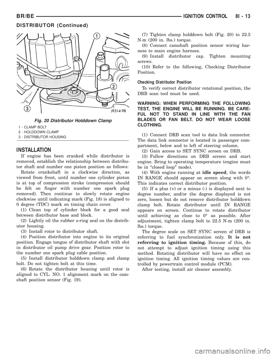
(6) Rotate the distributor housing until rotor is
aligned to CYL. NO. 1 alignment mark on the cam-
shaft position sensor (Fig. 19).(7) Tighten clamp holddown bolt (Fig. 20) to 22.5
N´m (200 in. lbs.) torque.
(8) Connect camshaft position sensor wiring har-
ness to main engine harness.
(9) Install distributor cap. Tighten mounting
screws.
(10) Refer to the following, Checking Distributor
Position.
Checking Distributor Position
To verify correct distributor rotational position, the
DRB scan tool must be used.
WARNING: WHEN PERFORMING THE FOLLOWING
TEST, THE ENGINE WILL BE RUNNING. BE CARE-
FUL NOT TO STAND IN LINE WITH THE FAN
BLADES OR FAN BELT. DO NOT WEAR LOOSE
CLOTHING.
(1) Connect DRB scan tool to data link connector.
The data link connector is located in passenger com-
partment, below and to left of steering column.
(2) Gain access to SET SYNC screen on DRB.
(3) Follow directions on DRB screen and start
engine. Bring to operating temperature (engine must
be in ªclosed loopº mode).
(4) With engine running atidle speed, the words
IN RANGE should appear on screen along with 0É.
This indicates correct distributor position.
(5) If a plus (+) or a minus (-) is displayed next to
degree number, and/or the degree displayed is not
zero, loosen but do not remove distributor holddown
clamp bolt. Rotate distributor until IN RANGE
appears on screen. Continue to rotate distributor
until achieving as close to 0É as possible. After
adjustment, tighten clamp bolt to 22.5 N´m (200 in.
lbs.) torque.
The degree scale on SET SYNC screen of DRB is
referring to fuel synchronization only.It is not
referring to ignition timing.Because of this, do
not attempt to adjust ignition timing using this
method. Rotating distributor will have no effect on
ignition timing. All ignition timing values are con-
trolled by powertrain control module (PCM).
After testing, install air cleaner assembly.
Fig. 20 Distributor Holddown Clamp
1 - CLAMP BOLT
2 - HOLDDOWN CLAMP
3 - DISTRIBUTOR HOUSING
BR/BEIGNITION CONTROL 8I - 13
DISTRIBUTOR (Continued)
Page 473 of 2255
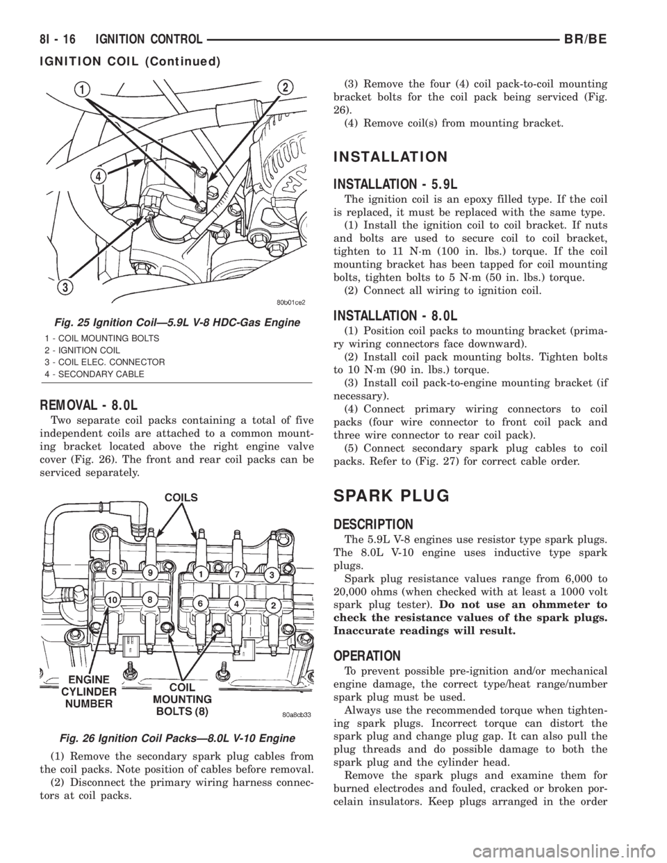
REMOVAL - 8.0L
Two separate coil packs containing a total of five
independent coils are attached to a common mount-
ing bracket located above the right engine valve
cover (Fig. 26). The front and rear coil packs can be
serviced separately.
(1) Remove the secondary spark plug cables from
the coil packs. Note position of cables before removal.
(2) Disconnect the primary wiring harness connec-
tors at coil packs.(3) Remove the four (4) coil pack-to-coil mounting
bracket bolts for the coil pack being serviced (Fig.
26).
(4) Remove coil(s) from mounting bracket.
INSTALLATION
INSTALLATION - 5.9L
The ignition coil is an epoxy filled type. If the coil
is replaced, it must be replaced with the same type.
(1) Install the ignition coil to coil bracket. If nuts
and bolts are used to secure coil to coil bracket,
tighten to 11 N´m (100 in. lbs.) torque. If the coil
mounting bracket has been tapped for coil mounting
bolts, tighten bolts to 5 N´m (50 in. lbs.) torque.
(2) Connect all wiring to ignition coil.
INSTALLATION - 8.0L
(1) Position coil packs to mounting bracket (prima-
ry wiring connectors face downward).
(2) Install coil pack mounting bolts. Tighten bolts
to 10 N´m (90 in. lbs.) torque.
(3) Install coil pack-to-engine mounting bracket (if
necessary).
(4) Connect primary wiring connectors to coil
packs (four wire connector to front coil pack and
three wire connector to rear coil pack).
(5) Connect secondary spark plug cables to coil
packs. Refer to (Fig. 27) for correct cable order.
SPARK PLUG
DESCRIPTION
The 5.9L V-8 engines use resistor type spark plugs.
The 8.0L V-10 engine uses inductive type spark
plugs.
Spark plug resistance values range from 6,000 to
20,000 ohms (when checked with at least a 1000 volt
spark plug tester).Do not use an ohmmeter to
check the resistance values of the spark plugs.
Inaccurate readings will result.
OPERATION
To prevent possible pre-ignition and/or mechanical
engine damage, the correct type/heat range/number
spark plug must be used.
Always use the recommended torque when tighten-
ing spark plugs. Incorrect torque can distort the
spark plug and change plug gap. It can also pull the
plug threads and do possible damage to both the
spark plug and the cylinder head.
Remove the spark plugs and examine them for
burned electrodes and fouled, cracked or broken por-
celain insulators. Keep plugs arranged in the order
Fig. 25 Ignition CoilÐ5.9L V-8 HDC-Gas Engine
1 - COIL MOUNTING BOLTS
2 - IGNITION COIL
3 - COIL ELEC. CONNECTOR
4 - SECONDARY CABLE
Fig. 26 Ignition Coil PacksÐ8.0L V-10 Engine
8I - 16 IGNITION CONTROLBR/BE
IGNITION COIL (Continued)
Page 475 of 2255
cause of oil entry into that particular combustion
chamber.
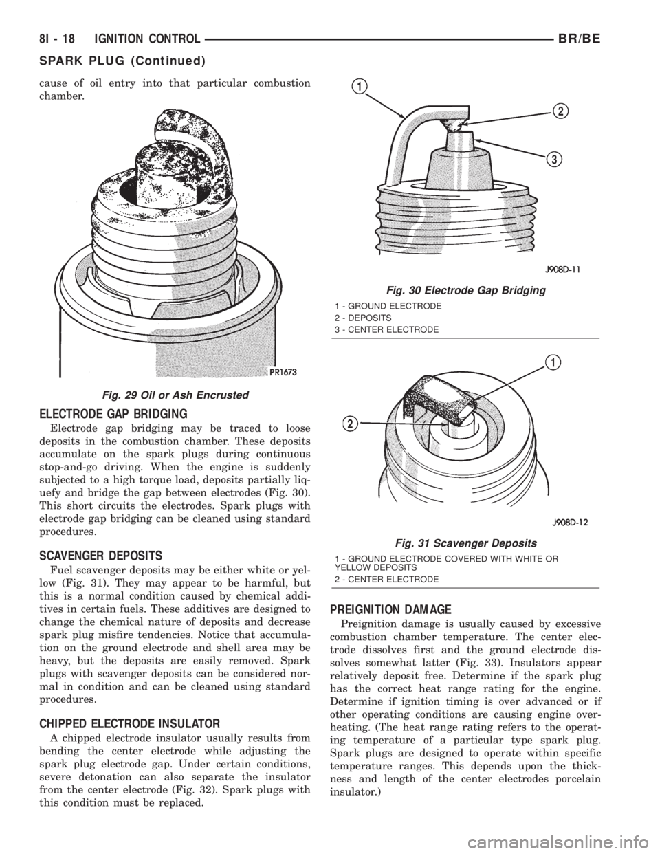
ELECTRODE GAP BRIDGING
Electrode gap bridging may be traced to loose
deposits in the combustion chamber. These deposits
accumulate on the spark plugs during continuous
stop-and-go driving. When the engine is suddenly
subjected to a high torque load, deposits partially liq-
uefy and bridge the gap between electrodes (Fig. 30).
This short circuits the electrodes. Spark plugs with
electrode gap bridging can be cleaned using standard
procedures.
SCAVENGER DEPOSITS
Fuel scavenger deposits may be either white or yel-
low (Fig. 31). They may appear to be harmful, but
this is a normal condition caused by chemical addi-
tives in certain fuels. These additives are designed to
change the chemical nature of deposits and decrease
spark plug misfire tendencies. Notice that accumula-
tion on the ground electrode and shell area may be
heavy, but the deposits are easily removed. Spark
plugs with scavenger deposits can be considered nor-
mal in condition and can be cleaned using standard
procedures.
CHIPPED ELECTRODE INSULATOR
A chipped electrode insulator usually results from
bending the center electrode while adjusting the
spark plug electrode gap. Under certain conditions,
severe detonation can also separate the insulator
from the center electrode (Fig. 32). Spark plugs with
this condition must be replaced.
PREIGNITION DAMAGE
Preignition damage is usually caused by excessive
combustion chamber temperature. The center elec-
trode dissolves first and the ground electrode dis-
solves somewhat latter (Fig. 33). Insulators appear
relatively deposit free. Determine if the spark plug
has the correct heat range rating for the engine.
Determine if ignition timing is over advanced or if
other operating conditions are causing engine over-
heating. (The heat range rating refers to the operat-
ing temperature of a particular type spark plug.
Spark plugs are designed to operate within specific
temperature ranges. This depends upon the thick-
ness and length of the center electrodes porcelain
insulator.)
Fig. 29 Oil or Ash Encrusted
Fig. 30 Electrode Gap Bridging
1 - GROUND ELECTRODE
2 - DEPOSITS
3 - CENTER ELECTRODE
Fig. 31 Scavenger Deposits
1 - GROUND ELECTRODE COVERED WITH WHITE OR
YELLOW DEPOSITS
2 - CENTER ELECTRODE
8I - 18 IGNITION CONTROLBR/BE
SPARK PLUG (Continued)
Page 477 of 2255

(2) Prior to removing the spark plug, spray com-
pressed air around the spark plug hole and the area
around the spark plug. This will help prevent foreign
material from entering the combustion chamber.
(3) Remove the spark plug using a quality socket
with a rubber or foam insert.
(4) Inspect the spark plug condition. Refer to
Spark Plug Condition in the Diagnostics and Testing
section of this group.
CLEANING
The plugs may be cleaned using commercially
available spark plug cleaning equipment. After clean-
ing, file center electrode flat with a small point file or
jewelers file before adjusting gap.
CAUTION: Never use a motorized wire wheel brush
to clean spark plugs. Metallic deposits will remain
on spark plug insulator and will cause plug misfire.
INSTALLATION
Special care should be taken when installing spark
plugs into the cylinder head spark plug wells. Be
sure the plugs do not drop into the plug wells as elec-
trodes can be damaged.
Always tighten spark plugs to the specified torque.
Over tightening can cause distortion resulting in a
change in the spark plug gap or a cracked porcelain
insulator.
When replacing the spark plug and ignition coil
cables, route the cables correctly and secure them in
the appropriate retainers. Failure to route the cables
properly can cause the radio to reproduce ignition
noise. It could cause cross ignition of the spark plugs
or short circuit the cables to ground.
(1) Start the spark plug into the cylinder head by
hand to avoid cross threading.
(2) Tighten spark plugs to 35-41 N´m (26-30 ft.
lbs.) torque.
(3) Install spark plug cables over spark plugs.
SPARK PLUG CABLE
DESCRIPTION
Spark plug cables are sometimes referred to as sec-
ondary ignition wires.
OPERATION
The spark plug cables transfer electrical current
from the ignition coil(s) and/or distributor, to individ-
ual spark plugs at each cylinder. The resistive spark
plug cables are of nonmetallic construction. The
cables provide suppression of radio frequency emis-
sions from the ignition system.
DIAGNOSIS AND TESTING - SPARK PLUG
CABLES
Cable routing is important on certain engines. To
prevent possible ignition crossfire, be sure the cables
are clipped into the plastic routing looms. Try to pre-
vent any one cable from contacting another. Before
removing cables, note their original location and
routing. Never allow one cable to be twisted around
another.
Check the spark plug cable connections for good
contact at the coil(s), distributor cap towers, and
spark plugs. Terminals should be fully seated. The
insulators should be in good condition and should fit
tightly on the coil, distributor and spark plugs. Spark
plug cables with insulators that are cracked or torn
must be replaced.
Clean high voltage ignition cables with a cloth
moistened with a non-flammable solvent. Wipe the
cables dry. Check for brittle or cracked insulation.
On 5.9L engines, spark plug cable heat shields are
pressed into the cylinder head to surround each
spark plug cable boot and spark plug (Fig. 36). These
shields protect the spark plug boots from damage
(due to intense engine heat generated by the exhaust
manifolds) and should not be removed. After the
spark plug cable has been installed, the lip of the
cable boot should have a small air gap to the top of
the heat shield (Fig. 36).
TESTING
When testing secondary cables for damage with an
oscilloscope, follow the instructions of the equipment
manufacturer.
If an oscilloscope is not available, spark plug cables
may be tested as follows:
Fig. 36 Heat ShieldsÐ5.9L Engines
1 - AIR GAP
2 - SPARK PLUG BOOT HEAT SHIELD
8I - 20 IGNITION CONTROLBR/BE
SPARK PLUG (Continued)
Page 604 of 2255
may be damaged. Service replacement clocksprings
are shipped pre-centered and with the auto-locking
tabs engaged. A piece of tape covers the auto-locking
tabs to discourage tampering. These auto-locking
tabs should not be disengaged until the clockspring
has been installed on the steering column. If this
shipping tape is removed or damaged, or if the auto-
locking tabs are disengaged before the clockspring is
installed on a steering column, the clockspring cen-
tering procedure must be performed. (Refer to 8 -
ELECTRICAL/RESTRAINTS/CLOCKSPRING -
STANDARD PROCEDURE - CLOCKSPRING CEN-
TERING).
STANDARD PROCEDURE - CLOCKSPRING
CENTERING
The clockspring is designed to wind and unwind
when the steering wheel is rotated, but is only
designed to rotate the same number of turns (about
five complete rotations) as the steering wheel can be
turned from stop to stop. Centering the clockspring
indexes the clockspring tape to other steering compo-
nents so that it can operate within its designed
travel limits. The rotor of a centered clockspring can
be rotated two and one-half turns in either direction
from the centered position, without damaging the
clockspring tape.
However, if the clockspring is removed for service
or if the steering column is disconnected from the
steering gear, the clockspring tape can change posi-
tion relative to the other steering components. The
clockspring must then be re-centered following com-
pletion of such service or the clockspring tape may be
damaged. Service replacement clocksprings are
shipped pre-centered and with the auto-locking tabs
engaged (raised). These auto-locking tabs should not
be disengaged until the clockspring has been
installed on the steering column. If the auto-locking
tabs are disengaged before the clockspring is
installed on a steering column, the clockspring cen-
tering procedure must be performed.
WARNING: DISABLE THE AIRBAG SYSTEM
BEFORE ATTEMPTING ANY STEERING WHEEL,
STEERING COLUMN, OR INSTRUMENT PANEL
COMPONENT DIAGNOSIS OR SERVICE. DISCON-
NECT AND ISOLATE THE BATTERY NEGATIVE
(GROUND) CABLE, THEN WAIT TWO MINUTES FOR
THE AIRBAG SYSTEM CAPACITOR TO DISCHARGE
BEFORE PERFORMING FURTHER DIAGNOSIS OR
SERVICE. THIS IS THE ONLY SURE WAY TO DIS-
ABLE THE AIRBAG SYSTEM. FAILURE TO TAKE
THE PROPER PRECAUTIONS COULD RESULT IN
ACCIDENTAL AIRBAG DEPLOYMENT AND POSSI-
BLE PERSONAL INJURY.NOTE: Before starting this procedure, be certain to
turn the steering wheel until the front wheels are in
the straight-ahead position.
(1) Place the front wheels in the straight-ahead
position.
(2) Remove the clockspring from the steering col-
umn. (Refer to 8 - ELECTRICAL/RESTRAINTS/
CLOCKSPRING - REMOVAL).
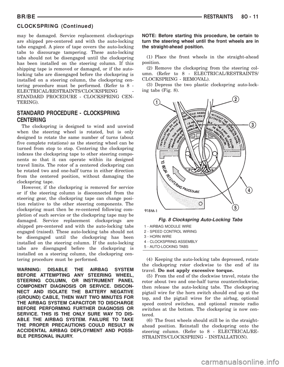
(3) Depress the two plastic clockspring auto-lock-
ing tabs (Fig. 8).
(4) Keeping the auto-locking tabs depressed, rotate
the clockspring rotor clockwise to the end of its
travel.Do not apply excessive torque.
(5) From the end of the clockwise travel, rotate the
rotor about two and one-half turns counterclockwise,
then release the auto-locking tabs. The clockspring
pigtail wire for the horn switch should end up at the
top, and the pigtail wires for the airbag, optional
speed control switches, and optional remote radio
switches at the bottom. The clockspring is now cen-
tered.
(6) The front wheels should still be in the straight-
ahead position. Reinstall the clockspring onto the
steering column. (Refer to 8 - ELECTRICAL/RE-
STRAINTS/CLOCKSPRING - INSTALLATION).
Fig. 8 Clockspring Auto-Locking Tabs
1 - AIRBAG MODULE WIRE
2 - SPEED CONTROL WIRING
3 - HORN WIRE
4 - CLOCKSPRING ASSEMBLY
5 - AUTO-LOCKING TABS
BR/BERESTRAINTS 8O - 11
CLOCKSPRING (Continued)
Page 624 of 2255
SPEED CONTROL
TABLE OF CONTENTS
page page
SPEED CONTROL
DESCRIPTION
DESCRIPTION - SPEED CONTROL SYSTEM . 1
DESCRIPTION - VEHICLE SPEED INPUT....2
OPERATION - SPEED CONTROL SYSTEM....2
DIAGNOSIS AND TESTING
DIAGNOSIS AND TESTING - VACUUM
SUPPLY TEST.........................3
DIAGNOSIS AND TESTING - ROAD TEST....4
SPECIFICATIONS
TORQUE - SPEED CONTROL SYSTEM.....4
CABLE
DESCRIPTION..........................4
OPERATION............................4
REMOVAL
REMOVAL - GAS ENGINES...............4
REMOVAL - DIESEL WITH AUTO. TRANS. . . . 5
INSTALLATION
INSTALLATION - GAS ENGINES...........5
INSTALLATION - DIESEL WITH AUTO.
TRANS...............................6SPEED CONTROL SERVO
DESCRIPTION..........................6
OPERATION............................6
REMOVAL
REMOVAL............................6
REMOVAL - DIESEL WITH AUTO. TRANS. . . . 9
INSTALLATION
INSTALLATION.......................11
INSTALLATION - DIESEL WITH AUTO.
TRANS..............................12
SWITCH
DESCRIPTION.........................12
OPERATION...........................12
REMOVAL.............................13
INSTALLATION.........................14
VACUUM RESERVOIR
DESCRIPTION.........................14
REMOVAL.............................14
INSTALLATION.........................15
SPEED CONTROL
DESCRIPTION
DESCRIPTION - SPEED CONTROL SYSTEM
Gas Engines and/or Diesel With Automatic Trans.
The speed control system is operated by the use of
a cable and a vacuum controlled servo. Electronic
control of the speed control system is integrated into
the Powertrain Control Module (PCM). The controls
consist of two steering wheel mounted switches. The
switches are labeled: ON/OFF, RES/ACCEL, SET,
COAST, and CANCEL.
The system is designed to operate at speeds above
30 mph (50 km/h).
WARNING: THE USE OF SPEED CONTROL IS NOT
RECOMMENDED WHEN DRIVING CONDITIONS DO
NOT PERMIT MAINTAINING A CONSTANT SPEED,
SUCH AS IN HEAVY TRAFFIC OR ON ROADS THATARE WINDING, ICY, SNOW COVERED, OR SLIP-
PERY.
Diesel With Manual Trans.
The speed control system is fully electronically con-
trolled by the Engine Control Module (ECM).A
cable and a vacuum controlled servo are not
used if the vehicle is equipped with a manual
transmission and a diesel engine. This is a ser-
vo-less system.The controls consist of two steering
wheel mounted switches. The switches are labeled:
ON/OFF, RES/ACCEL, SET, COAST, and CANCEL.
The system is designed to operate at speeds above
30 mph (50 km/h).
WARNING: THE USE OF SPEED CONTROL IS NOT
RECOMMENDED WHEN DRIVING CONDITIONS DO
NOT PERMIT MAINTAINING A CONSTANT SPEED,
SUCH AS IN HEAVY TRAFFIC OR ON ROADS THAT
ARE WINDING, ICY, SNOW COVERED, OR SLIP-
PERY.
BR/BESPEED CONTROL 8P - 1