2002 DODGE RAM headlamp
[x] Cancel search: headlampPage 2029 of 2255
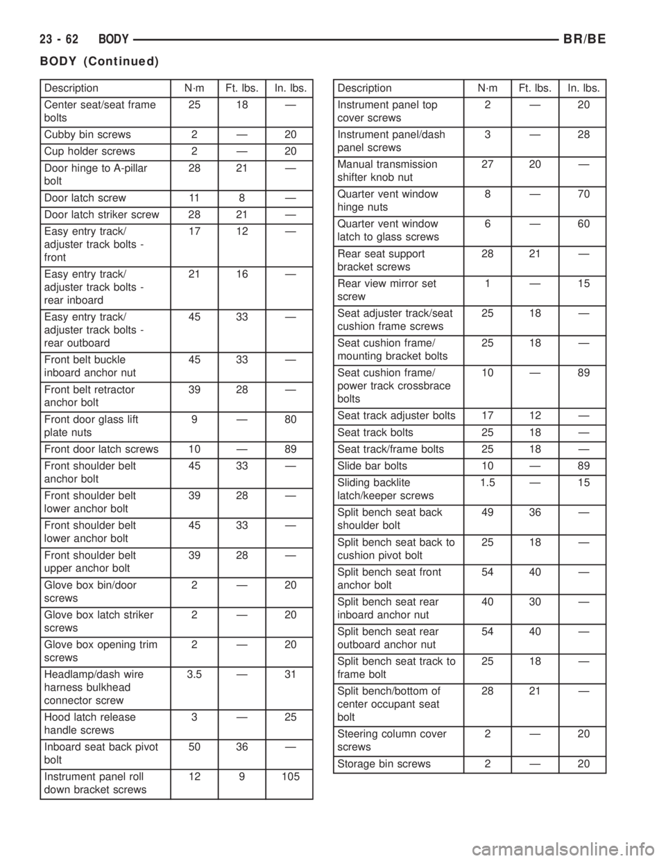
Description N´m Ft. lbs. In. lbs.
Center seat/seat frame
bolts25 18 Ð
Cubby bin screws 2 Ð 20
Cup holder screws 2 Ð 20
Door hinge to A-pillar
bolt28 21 Ð
Door latch screw 11 8 Ð
Door latch striker screw 28 21 Ð
Easy entry track/
adjuster track bolts -
front17 12 Ð
Easy entry track/
adjuster track bolts -
rear inboard21 16 Ð
Easy entry track/
adjuster track bolts -
rear outboard45 33 Ð
Front belt buckle
inboard anchor nut45 33 Ð
Front belt retractor
anchor bolt39 28 Ð
Front door glass lift
plate nuts9Ð80
Front door latch screws 10 Ð 89
Front shoulder belt
anchor bolt45 33 Ð
Front shoulder belt
lower anchor bolt39 28 Ð
Front shoulder belt
lower anchor bolt45 33 Ð
Front shoulder belt
upper anchor bolt39 28 Ð
Glove box bin/door
screws2Ð20
Glove box latch striker
screws2Ð20
Glove box opening trim
screws2Ð20
Headlamp/dash wire
harness bulkhead
connector screw3.5 Ð 31
Hood latch release
handle screws3Ð25
Inboard seat back pivot
bolt50 36 Ð
Instrument panel roll
down bracket screws12 9 105Description N´m Ft. lbs. In. lbs.
Instrument panel top
cover screws2Ð20
Instrument panel/dash
panel screws3Ð28
Manual transmission
shifter knob nut27 20 Ð
Quarter vent window
hinge nuts8Ð70
Quarter vent window
latch to glass screws6Ð60
Rear seat support
bracket screws28 21 Ð
Rear view mirror set
screw1Ð15
Seat adjuster track/seat
cushion frame screws25 18 Ð
Seat cushion frame/
mounting bracket bolts25 18 Ð
Seat cushion frame/
power track crossbrace
bolts10 Ð 89
Seat track adjuster bolts 17 12 Ð
Seat track bolts 25 18 Ð
Seat track/frame bolts 25 18 Ð
Slide bar bolts 10 Ð 89
Sliding backlite
latch/keeper screws1.5 Ð 15
Split bench seat back
shoulder bolt49 36 Ð
Split bench seat back to
cushion pivot bolt25 18 Ð
Split bench seat front
anchor bolt54 40 Ð
Split bench seat rear
inboard anchor nut40 30 Ð
Split bench seat rear
outboard anchor nut54 40 Ð
Split bench seat track to
frame bolt25 18 Ð
Split bench/bottom of
center occupant seat
bolt28 21 Ð
Steering column cover
screws2Ð20
Storage bin screws 2 Ð 20
23 - 62 BODYBR/BE
BODY (Continued)
Page 2060 of 2255
LEFT FRONT FENDER
REMOVAL
(1) Remove front bumper (Refer to 13 - FRAMES
& BUMPERS/BUMPERS/FRONT BUMPER -
REMOVAL).
(2) Remove air cleaner from wheelhouse (DIESEL
ONLY).
(3) Remove coolant overflow bottle (V-10 ONLY).
(4) Remove battery tray (Refer to 8 - ELECTRI-
CAL/BATTERY SYSTEM/TRAY - REMOVAL).
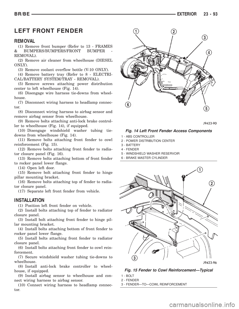
(5) Remove screws attaching power distribution
center to left wheelhouse (Fig. 14).
(6) Disengage wire harness tie-downs from wheel-
house.
(7) Disconnect wiring harness to headlamp connec-
tor.
(8) Disconnect wiring harness to airbag sensor and
remove airbag sensor from wheelhouse.
(9) Remove bolts attaching anti-lock brake control-
ler to wheelhouse (Fig. 14), if equipped.
(10) Disengage windshield washer tubing tie-
downs from wheelhouse (Fig. 14).
(11) Remove bolts attaching front fender to cowl
reinforcement (Fig. 15).
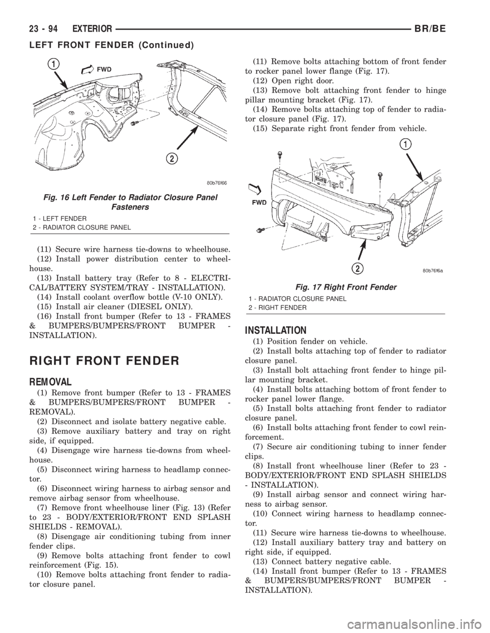
(12) Remove bolts attaching front fender to radia-
tor closure panel (Fig. 16).
(13) Remove bolts attaching bottom of front fender
to rocker panel lower flange.
(14) Open left door.
(15) Remove bolt attaching front fender to hinge
pillar mounting bracket.
(16) Remove bolts attaching top of fender to radia-
tor closure panel.
(17) Separate left front fender from vehicle.
INSTALLATION
(1) Position left front fender on vehicle.
(2) Install bolts attaching top of fender to radiator
closure panel.
(3) Install bolt attaching front fender to hinge pil-
lar mounting bracket.
(4) Install bolts attaching bottom of front fender to
rocker panel lower flange.
(5) Install bolts attaching front fender to radiator
closure panel.
(6) Install bolts attaching front fender to cowl rein-
forcement.
(7) Secure windshield washer tubing tie-downs to
wheelhouse.
(8) Install anti-lock brake controller to wheel-
house, if equipped.
(9) Install airbag sensor to wheelhouse and con-
nect wiring harness to airbag sensor.
(10) Connect wiring harness to headlamp connec-
tor.
Fig. 14 Left Front Fender Access Components
1 - ABS CONTROLLER
2 - POWER DISTRIBUTION CENTER
3 - BATTERY
4 - FENDER
5 - WINDSHIELD WASHER RESERVOIR
6 - BRAKE MASTER CYLINDER
Fig. 15 Fender to Cowl ReinforcementÐTypical
1 - BOLT
2 - FENDER
3 - FENDERÐTOÐCOWL REINFORCEMENT
BR/BEEXTERIOR 23 - 93
Page 2061 of 2255
(11) Secure wire harness tie-downs to wheelhouse.
(12) Install power distribution center to wheel-
house.
(13) Install battery tray (Refer to 8 - ELECTRI-
CAL/BATTERY SYSTEM/TRAY - INSTALLATION).
(14) Install coolant overflow bottle (V-10 ONLY).
(15) Install air cleaner (DIESEL ONLY).
(16) Install front bumper (Refer to 13 - FRAMES
& BUMPERS/BUMPERS/FRONT BUMPER -
INSTALLATION).
RIGHT FRONT FENDER
REMOVAL
(1) Remove front bumper (Refer to 13 - FRAMES
& BUMPERS/BUMPERS/FRONT BUMPER -
REMOVAL).
(2) Disconnect and isolate battery negative cable.
(3) Remove auxiliary battery and tray on right
side, if equipped.
(4) Disengage wire harness tie-downs from wheel-
house.
(5) Disconnect wiring harness to headlamp connec-
tor.
(6) Disconnect wiring harness to airbag sensor and
remove airbag sensor from wheelhouse.
(7) Remove front wheelhouse liner (Fig. 13) (Refer
to 23 - BODY/EXTERIOR/FRONT END SPLASH
SHIELDS - REMOVAL).
(8) Disengage air conditioning tubing from inner
fender clips.
(9) Remove bolts attaching front fender to cowl
reinforcement (Fig. 15).
(10) Remove bolts attaching front fender to radia-
tor closure panel.(11) Remove bolts attaching bottom of front fender
to rocker panel lower flange (Fig. 17).
(12) Open right door.
(13) Remove bolt attaching front fender to hinge
pillar mounting bracket (Fig. 17).
(14) Remove bolts attaching top of fender to radia-
tor closure panel (Fig. 17).
(15) Separate right front fender from vehicle.
INSTALLATION
(1) Position fender on vehicle.
(2) Install bolts attaching top of fender to radiator
closure panel.
(3) Install bolt attaching front fender to hinge pil-
lar mounting bracket.
(4) Install bolts attaching bottom of front fender to
rocker panel lower flange.
(5) Install bolts attaching front fender to radiator
closure panel.
(6) Install bolts attaching front fender to cowl rein-
forcement.
(7) Secure air conditioning tubing to inner fender
clips.
(8) Install front wheelhouse liner (Refer to 23 -
BODY/EXTERIOR/FRONT END SPLASH SHIELDS
- INSTALLATION).
(9) Install airbag sensor and connect wiring har-
ness to airbag sensor.
(10) Connect wiring harness to headlamp connec-
tor.
(11) Secure wire harness tie-downs to wheelhouse.
(12) Install auxiliary battery tray and battery on
right side, if equipped.
(13) Connect battery negative cable.
(14) Install front bumper (Refer to 13 - FRAMES
& BUMPERS/BUMPERS/FRONT BUMPER -
INSTALLATION).
Fig. 16 Left Fender to Radiator Closure Panel
Fasteners
1 - LEFT FENDER
2 - RADIATOR CLOSURE PANEL
Fig. 17 Right Front Fender
1 - RADIATOR CLOSURE PANEL
2 - RIGHT FENDER
23 - 94 EXTERIORBR/BE
LEFT FRONT FENDER (Continued)
Page 2073 of 2255
²Glove Box- The hinged bin-type glove box in
the passenger side of the instrument panel features a
recessed paddle-operated latch handle. Three molded
hook formations on the lower edge of the glove box
door are engaged with and pivot on three hinge pins
integral to the lower edge of the instrument panel
support structure. The glove box door also serves as
the passenger side knee blocker. A honeycomb struc-
ture between the inner and outer glove box door pan-
els helps to absorb the impact load and distribute it
to the instrument panel structure.
²Steering Column Opening Cover- The steer-
ing column opening cover serves as the driver side
knee blocker. This molded plastic cover has an inte-
gral ribbed plastic liner concealed behind it, for
increased strength and integrity. The steering column
opening cover transfers impact loads to the instru-
ment panel structural support.
²Top Cover- The instrument panel top cover or
base trim is the molded, grained, and color impreg-
nated plastic outer skin of the instrument panel
structural support.
Hard wired circuitry connects the electrical compo-
nents on the instrument panel to each other through
the electrical system of the vehicle. These hard wired
circuits are integral to several wire harnesses, which
are routed throughout the vehicle and retained by
many different methods. These circuits may be con-
nected to each other, to the vehicle electrical system
and to the instrument panel components through the
use of a combination of soldered splices, splice block
connectors and many different types of wire harness
terminal connectors and insulators. Refer to the
appropriate wiring information. The wiring informa-
tion includes complete circuit diagrams, proper wire
and connector repair procedures, further details on
wire harness routing and retention, as well as pin-
out and location views for the various wire harness
connectors, splices, and grounds.
OPERATION
The instrument panel serves as the command cen-
ter of the vehicle, which necessarily makes it a very
complex unit. The instrument panel is designed to
house the controls and monitors for standard and
optional powertrains, climate control systems, audio
systems, safety systems, and many other comfort or
convenience items. When the components of the
instrument panel structural support are properly
assembled and secured in the vehicle they provide
superior instrument panel stiffness and integrity to
help reduce buzzes, squeaks, and rattles. This type of
construction also provides improved energy absorp-
tion which, in conjunction with the dual airbags and
seat belts, helps to improve occupant protection.The instrument panel is also designed so that all of
the various controls can be safely reached and the
monitors can be easily viewed by the vehicle operator
when driving, while still allowing relative ease of
access to each of these items for service. Modular
instrument panel construction allows all of the
gauges and controls to be serviced from the front of
the panel. In addition, most of the instrument panel
electrical components can be accessed without com-
plete instrument panel removal. However, if neces-
sary, the instrument panel can be removed from the
vehicle as an assembly.
The steering column opening cover with its inte-
gral knee blocker located on the driver side of the
instrument panel works in conjunction with the air-
bag system in a frontal vehicle impact to keep the
driver properly positioned for an airbag deployment.
In addition, removal of this component provides
access to the steering column mounts, the steering
column wiring, the Junction Block (JB) (removal of a
snap-fit fuse access panel on the left end of the
instrument panel allows access to the fuses and cir-
cuit breakers), the Central Timer Module (CTM), the
Infinity speaker filter choke and relay unit, much of
the instrument panel wiring, and the gear selector
indicator cable (automatic transmission).
In a frontal collision, the glove box door on the pas-
senger side of the instrument panel provides the
same function for the front seat passenger as the
knee blocker does for the driver. The glove box door
also incorporates a recessed latch handle. Removal of
the glove box provides access to the passenger airbag,
the glove box lamp and switch, the radio antenna
coaxial cable, the heating and air conditioning vac-
uum harness connector, and additional instrument
panel wiring.
Removal of the instrument panel cluster bezel
allows access to the headlamp switch, instrument
cluster, radio, passenger airbag on-off switch, heated
seat switches (if equipped), and the heating and air
conditioning control. Removal of the instrument clus-
ter allows access to the cluster illumination and indi-
cator bulbs, and more of the instrument panel
wiring. Complete instrument panel removal is
required for service of most components internal to
the heating and air conditioning system housing,
including the heater core and the evaporator.
See the owner's manual in the vehicle glove box for
more information on the features, use and operation
of all of the components and systems mounted on or
in the instrument panel.
23 - 106 INSTRUMENT PANEL SYSTEMBR/BE
INSTRUMENT PANEL SYSTEM (Continued)
Page 2083 of 2255
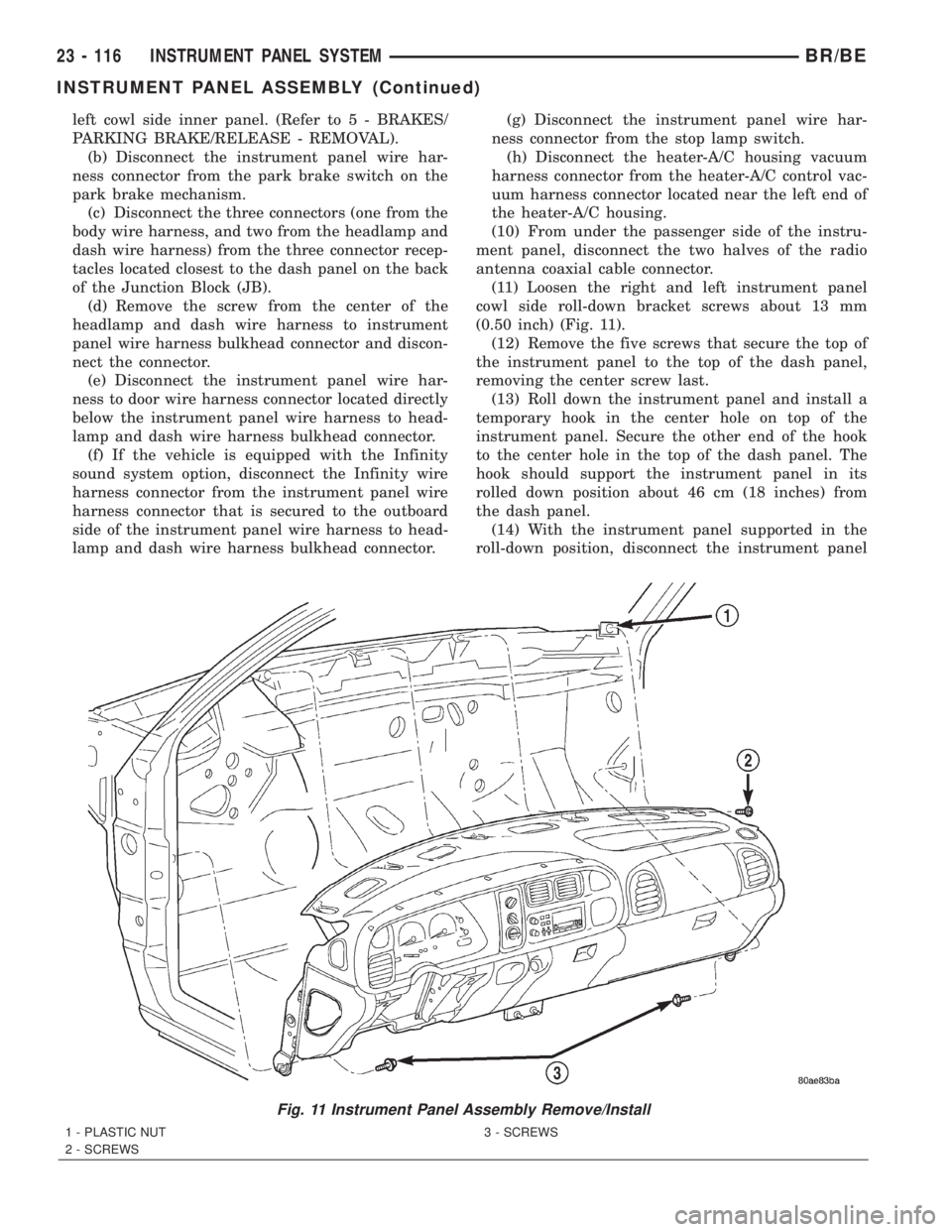
left cowl side inner panel. (Refer to 5 - BRAKES/
PARKING BRAKE/RELEASE - REMOVAL).
(b) Disconnect the instrument panel wire har-
ness connector from the park brake switch on the
park brake mechanism.
(c) Disconnect the three connectors (one from the
body wire harness, and two from the headlamp and
dash wire harness) from the three connector recep-
tacles located closest to the dash panel on the back
of the Junction Block (JB).
(d) Remove the screw from the center of the
headlamp and dash wire harness to instrument
panel wire harness bulkhead connector and discon-
nect the connector.
(e) Disconnect the instrument panel wire har-
ness to door wire harness connector located directly
below the instrument panel wire harness to head-
lamp and dash wire harness bulkhead connector.
(f) If the vehicle is equipped with the Infinity
sound system option, disconnect the Infinity wire
harness connector from the instrument panel wire
harness connector that is secured to the outboard
side of the instrument panel wire harness to head-
lamp and dash wire harness bulkhead connector.(g) Disconnect the instrument panel wire har-
ness connector from the stop lamp switch.
(h) Disconnect the heater-A/C housing vacuum
harness connector from the heater-A/C control vac-
uum harness connector located near the left end of
the heater-A/C housing.
(10) From under the passenger side of the instru-
ment panel, disconnect the two halves of the radio
antenna coaxial cable connector.
(11) Loosen the right and left instrument panel
cowl side roll-down bracket screws about 13 mm
(0.50 inch) (Fig. 11).
(12) Remove the five screws that secure the top of
the instrument panel to the top of the dash panel,
removing the center screw last.
(13) Roll down the instrument panel and install a
temporary hook in the center hole on top of the
instrument panel. Secure the other end of the hook
to the center hole in the top of the dash panel. The
hook should support the instrument panel in its
rolled down position about 46 cm (18 inches) from
the dash panel.
(14) With the instrument panel supported in the
roll-down position, disconnect the instrument panel
Fig. 11 Instrument Panel Assembly Remove/Install
1 - PLASTIC NUT
2 - SCREWS3 - SCREWS
23 - 116 INSTRUMENT PANEL SYSTEMBR/BE
INSTRUMENT PANEL ASSEMBLY (Continued)
Page 2084 of 2255
wire harness connectors from the heater-A/C housing
wire harness connectors.
(15) With the aid of an assistant, remove the tem-
porary hook and lift the instrument panel assembly
off of the roll-down bracket screws and remove it
from the vehicle.
INSTALLATION
WARNING: ON VEHICLES EQUIPPED WITH AIRBAGS,
DISABLE THE AIRBAG SYSTEM BEFORE ATTEMPT-
ING ANY STEERING WHEEL, STEERING COLUMN,
SEAT BELT TENSIONER, OR INSTRUMENT PANEL
COMPONENT DIAGNOSIS OR SERVICE. DISCONNECT
AND ISOLATE THE BATTERY NEGATIVE (GROUND)
CABLE, THEN WAIT TWO MINUTES FOR THE AIRBAG
SYSTEM CAPACITOR TO DISCHARGE BEFORE PER-
FORMING FURTHER DIAGNOSIS OR SERVICE. THIS IS
THE ONLY SURE WAY TO DISABLE THE AIRBAG SYS-
TEM. FAILURE TO TAKE THE PROPER PRECAUTIONS
COULD RESULT IN ACCIDENTAL AIRBAG DEPLOY-
MENT AND POSSIBLE PERSONAL INJURY.
(1)With the aid of an assistant, load the instrument
panel assembly onto the roll-down bracket screws on
the cowl side inner panels in the vehicle (Fig. 11).
Install a temporary hook in the center hole on top of the
instrument panel. Secure the other end of the hook to
the center hole in the top of the dash panel. The hook
should support the instrument panel in its rolled down
position about 46 cm (18 inches) from the dash panel.
(2) With the instrument panel supported in the
roll-down position, reconnect the instrument panel
wire harness connectors to the heater-A/C housing
wire harness connectors.
(3) Remove the temporary hook from the instru-
ment panel and roll the instrument panel up to its
installed position against the dash panel.
(4) Install and tighten the five screws that secure
the top of the instrument panel to the top of the dash
panel. Tighten the screws to 3.2 N´m (28 in. lbs.).
(5) Tighten the right and left instrument panel
cowl side roll-down bracket screws. Tighten the
screws to 11.9 N´m (105 in. lbs.).
(6) From under the passenger side of the instru-
ment panel, reconnect the two halves of the radio
antenna coaxial cable connector.
(7) From under the driver side of the instrument
panel, perform the following:
(a) Engage the park brake release handle link-
age rod with the park brake mechanism on the left
cowl side inner panel. (Refer to 5 - BRAKES/PARK-
ING BRAKE/RELEASE - INSTALLATION).
(b) Reconnect the instrument panel wire harness
connector to the park brake switch on the park
brake mechanism.(c) Reconnect the three connectors (one from the
body wire harness, and two from the headlamp and
dash wire harness) to the three connector recepta-
cles located closest to the dash panel on the back of
the Junction Block (JB).
(d)
Reconnect the headlamp and dash wire harness
to instrument panel wire harness bulkhead connector
and tighten the screw in the center of the connector.
Tighten the screw to 3.5 N´m (31 in. lbs.).
(e) Reconnect the instrument panel wire harness
to door wire harness connector located directly
below the instrument panel wire harness to head-
lamp and dash wire harness bulkhead connector.
(f) If the vehicle is equipped with the Infinity
sound system option, reconnect the Infinity wire
harness connector to the instrument panel wire
harness connector that is secured to the outboard
side of the instrument panel wire harness to head-
lamp and dash wire harness bulkhead connector.
(g) Reconnect the instrument panel wire harness
connector to the stop lamp switch.
(h) Reconnect the heater-A/C housing vacuum
harness connector to the heater-A/C control vac-
uum harness connector located near the left end of
the heater-A/C housing.
(8) Reinstall the steering column into the vehicle.
Be certain that the steering wheel was locked and
secured from rotation to prevent the loss of clock-
spring centering. (Refer to 19 - STEERING/COL-
UMN - INSTALLATION).
(9) If the vehicle is so equipped, reconnect the
overdrive lockout switch pigtail wire connector to the
instrument panel wire harness connector near the
instrument panel lower reinforcement.
(10) Reconnect the clockspring pigtail wire connec-
tor to the instrument panel wire harness connector
at the instrument panel lower reinforcement.
(11) Position the inside hood latch release handle
to the instrument panel lower reinforcement.
(12) Install and tighten the two screws that secure
the inside hood latch release handle to the instru-
ment panel lower reinforcement. Tighten the screws
to 2.8 N´m (25 in. lbs.).
(13) Reinstall the steering column opening cover
onto the instrument panel. (Refer to 23 - BODY/IN-
STRUMENT PANEL/STEERING COLUMN OPEN-
ING COVER - INSTALLATION).
(14) Reinstall the trim onto the left and right cowl
side inner panels. (Refer to 23 - BODY/INTERIOR/
COWL TRIM COVER - INSTALLATION).
(15) Reinstall the Airbag Control Module (ACM)
and bracket onto the floor panel transmission tunnel.
(Refer to 8 - ELECTRICAL/RESTRAINTS/AIRBAG
CONTROL MODULE - INSTALLATION).
(16) Reconnect the battery negative cable.
BR/BEINSTRUMENT PANEL SYSTEM 23 - 117
INSTRUMENT PANEL ASSEMBLY (Continued)
Page 2218 of 2255
ABS - DESCRIPTION, BRAKES...........5-35
ABS - OPERATION, BRAKES.............5-36
ABS BRAKE SYSTEM - STANDARD
PROCEDURE, BLEEDING................5-36
ABS INDICATOR - DESCRIPTION.........8J-14
ABS INDICATOR - OPERATION..........8J-14
A/C APPLICATION TABLE,
SPECIFICATIONS......................24-7
A/C COMPRESSOR - DESCRIPTION......24-46
A/C COMPRESSOR - DIAGNOSIS AND
TESTING...........................24-47
A/C COMPRESSOR - INSTALLATION......24-48
A/C COMPRESSOR - OPERATION........24-46
A/C COMPRESSOR - REMOVAL.........24-47
A/C COMPRESSOR CLUTCH -
DESCRIPTION.......................24-11
A/C COMPRESSOR CLUTCH -
INSPECTION........................24-15
A/C COMPRESSOR CLUTCH -
INSTALLATION.......................24-15
A/C COMPRESSOR CLUTCH -
OPERATION.........................24-13
A/C COMPRESSOR CLUTCH - REMOVAL . . 24-13
A/C COMPRESSOR CLUTCH BREAK-IN -
STANDARD PROCEDURE...............24-13
A/C COMPRESSOR CLUTCH COIL -
DIAGNOSIS AND TESTING.............24-13
A/C COMPRESSOR CLUTCH RELAY -
DESCRIPTION.......................24-17
A/C COMPRESSOR CLUTCH RELAY -
DIAGNOSIS AND TESTING...............24-17
A/C COMPRESSOR CLUTCH RELAY -
INSTALLATION.......................24-18
A/C COMPRESSOR CLUTCH RELAY -
OPERATION.........................24-17
A/C COMPRESSOR CLUTCH RELAY -
REMOVAL..........................24-18
A/C CONDENSER - DESCRIPTION........24-49
A/C CONDENSER - INSTALLATION.......24-50
A/C CONDENSER - OPERATION..........24-49
A/C CONDENSER - REMOVAL...........24-49
A/C EVAPORATOR - DESCRIPTION.......24-53
A/C EVAPORATOR - INSTALLATION......24-53
A/C EVAPORATOR - OPERATION.........24-53
A/C EVAPORATOR - REMOVAL..........24-53
A/C HEATER CONTROL - DIAGNOSIS
AND TESTING.......................24-18
A/C HIGH PRESSURE SWITCH -
DESCRIPTION.......................24-20
A/C HIGH PRESSURE SWITCH -
DIAGNOSIS AND TESTING.............24-20
A/C HIGH PRESSURE SWITCH -
INSTALLATION.......................24-20
A/C HIGH PRESSURE SWITCH -
OPERATION.........................24-20
A/C HIGH PRESSURE SWITCH -
REMOVAL..........................24-20
A/C LINE COUPLERS - DESCRIPTION.....24-40
A/C LINE COUPLERS - OPERATION......24-41
A/C LINE COUPLERS - STANDARD
PROCEDURE........................24-44
A/C LOW PRESSURE SWITCH -
DESCRIPTION.......................24-21
A/C LOW PRESSURE SWITCH -
DIAGNOSIS AND TESTING.............24-21
A/C LOW PRESSURE SWITCH -
INSTALLATION.......................24-21
A/C LOW PRESSURE SWITCH -
OPERATION
.........................24-21
A/C LOW PRESSURE SWITCH -
REMOVAL
..........................24-21
A/C ORIFICE TUBE - DESCRIPTION
.......24-54
A/C ORIFICE TUBE - INSTALLATION
......24-54
A/C ORIFICE TUBE - OPERATION
........24-54
A/C ORIFICE TUBE - REMOVAL
..........24-54
A/C PERFORMANCE - DIAGNOSIS AND
TESTING
............................24-2
ACCELERATOR PEDAL - INSTALLATION
. . . 14-37
ACCELERATOR PEDAL - REMOVAL
.......14-36
ACCELERATOR PEDAL POSITION
SENSOR - DESCRIPTION
...............14-95
ACCELERATOR PEDAL POSITION
SENSOR - INSTALLATION
..............14-97
ACCELERATOR PEDAL POSITION
SENSOR - OPERATION
................14-95
ACCELERATOR PEDAL POSITION
SENSOR - REMOVAL
..................14-95ACCESSORY DRIVE BELT - DIAGNOSIS
AND TESTING................7-24,7-27,7-30
ACCUMULATOR - DESCRIPTION.........24-55
ACCUMULATOR - DESCRIPTION . . 21-149,21-319
ACCUMULATOR - INSPECTION . . . 21-150,21-320
ACCUMULATOR - INSTALLATION........24-55
ACCUMULATOR - OPERATION..........24-55
ACCUMULATOR - OPERATION....21-150,21-320
ACCUMULATOR - REMOVAL............24-55
A/C-HEATER CONTROL - DESCRIPTION . . . 24-18
A/C-HEATER CONTROL - INSTALLATION . . . 24-19
A/C-HEATER CONTROL - OPERATION.....24-18
A/C-HEATER CONTROL - REMOVAL......24-19
ACTUATION TEST MODE - DESCRIPTION,
CIRCUIT.............................25-2
ACTUATOR - INSTALLATION, BLEND
DOOR.............................24-25
ACTUATOR - INSTALLATION, HEAT/
DEFROST DOOR.....................24-27
ACTUATOR - INSTALLATION, INSIDE
HANDLE.......................23-72,23-80
ACTUATOR - INSTALLATION, PANEL/
DEFROST DOOR.....................24-27
ACTUATOR - INSTALLATION,
RECIRCULATION DOOR................24-28
ACTUATOR - REMOVAL, BLEND DOOR....24-25
ACTUATOR - REMOVAL, HEAT/DEFROST
DOOR.............................24-26
ACTUATOR - REMOVAL, INSIDE HANDLE . 23-72,
23-80
ACTUATOR - REMOVAL, PANEL/DEFROST
DOOR.............................24-26
ACTUATOR - REMOVAL, RECIRCULATION
DOOR.............................24-27
ADAPTER - INSTALLATION, DEFROSTER
AND DEMISTER DUCT.................24-33
ADAPTER - REMOVAL, DEFROSTER AND
DEMISTER DUCT.....................24-33
ADAPTER BRACKET - INSTALLATION,
CAB CHASSIS.......................13-10
ADAPTER BRACKET - REMOVAL, CAB
CHASSIS...........................13-10
ADAPTER HOUSING SEAL - NV4500 -
INSTALLATION.......................21-42
ADAPTER HOUSING SEAL - NV4500 -
REMOVAL..........................21-42
ADAPTER HOUSING SEAL - NV5600 -
INSTALLATION.......................21-85
ADAPTER HOUSING SEAL - NV5600 -
REMOVAL..........................21-85
ADDING ADDITIONAL COOLANT -
STANDARD PROCEDURE................7-16
ADDITIONAL COOLANT - STANDARD
PROCEDURE, ADDING..................7-16
ADDITIVES - STANDARD PROCEDURE,
COOLANT SELECTION..................7-17
ADHESIVE LOCATIONS, SPECIFICATIONS
- STRUCTURAL......................23-44
ADJUSTER - INSTALLATION, SEAT BELT
TURNING LOOP.....................8O-29
ADJUSTER - INSTALLATION, SEAT
TRACK............................23-143
ADJUSTER - REMOVAL, SEAT BELT
TURNING LOOP.....................8O-29
ADJUSTER - REMOVAL, SEAT TRACK....23-143
ADJUSTER ASSEMBLY - INSTALLATION,
ROCKER ARM........................9-26
ADJUSTER ASSEMBLY - REMOVAL,
ROCKER ARM........................9-26
ADJUSTER ASSY - CLEANING, ROCKER
ARM ..............................9-146
ADJUSTER ASSY - DESCRIPTION,
ROCKER ARM.......................9-145
ADJUSTER ASSY - INSPECTION,
ROCKER ARM.......................9-146
ADJUSTER ASSY - INSTALLATION,
ROCKER ARM...................9-148,9-84
ADJUSTER ASSY - REMOVAL, ROCKER
ARM ..........................9-145,9-84
ADJUSTER KNOB - INSTALLATION,
TURNING LOOP HGT
.................8O-30
ADJUSTER KNOB - REMOVAL, TURNING
LOOP HGT
..........................8O-30
ADJUSTMENT - STANDARD
PROCEDURE, COMPASS VARIATION
......8M-4
ADJUSTMENT, ADJUSTMENTS
. . . 23-101,23-102,
23-103
ADJUSTMENT, ADJUSTMENTS
...........5-30ADJUSTMENT, ADJUSTMENTS...........13-2
ADJUSTMENT, ADJUSTMENTS . . . 21-208,21-380
ADJUSTMENT AND VERIFICATION -
STANDARD PROCEDURE, VALVE LASH....9-141
ADJUSTMENT, BANDS..........21-151,21-321
ADJUSTMENT, CARGO DOOR...........23-78
ADJUSTMENT, CENTER BEARING..........3-8
ADJUSTMENT, FRONT DOOR FORE/AFT . . . 23-69
ADJUSTMENT, FRONT DOOR IN/OUT.....23-70
ADJUSTMENT, FRONT DOOR LATCH......23-73
ADJUSTMENT, FRONT DOOR UP/DOWN . . . 23-70
ADJUSTMENT, PARKING BRAKE SHOES....5-33
ADJUSTMENT, SHIFT LEVER.....21-463,21-500
ADJUSTMENTS - ADJUSTMENT . . 23-101,23-102,
23-103
ADJUSTMENTS - ADJUSTMENT..........5-30
ADJUSTMENTS - ADJUSTMENT..........13-2
ADJUSTMENTS - ADJUSTMENT . . 21-208,21-380
ADJUSTMENTS, FOG LAMP UNIT........8L-13
ADJUSTMENTS, FRONT AXLE - 248FBI....3-19
ADJUSTMENTS, GEAR.................19-18
ADJUSTMENTS, HEADLAMP UNIT.......8L-21
ADJUSTMENTS, REAR AXLE - 248RBI.....3-51
ADJUSTMENTS, REAR AXLE - 267RBI.....3-83
ADJUSTMENTS, REAR AXLE - 286RBI....3-112
ADJUSTMENTS, TRANSMISSION
THROTTLE VALVE CABLE.........21-210,21-382
ADJUSTMENTS, VALVE BODY....21-257,21-428
AIR BLEED - STANDARD PROCEDURE....14-61
AIR CLEANER ELEMENT - INSTALLATION . . 9-130
AIR CLEANER ELEMENT - REMOVAL.....9-129
AIR CONDITIONER - DESCRIPTION,
HEATER .............................24-1
AIR CONDITIONER - OPERATION,
HEATER .............................24-1
AIR CONDITIONING - INSTALLATION,
WATER PUMP BYPASS HOSE WITH.......7-76
AIR CONDITIONING - INSTALLATION,
WATER PUMP BYPASS HOSE
WITHOUT............................7-77
AIR CONDITIONING - REMOVAL, WATER
PUMP BYPASS HOSE WITH.............7-73
AIR CONDITIONING - REMOVAL, WATER
PUMP BYPASS HOSE WITHOUT..........7-76
AIR CONTROL MOTOR - DESCRIPTION,
IDLE...............................14-40
AIR CONTROL MOTOR - OPERATION,
IDLE...............................14-40
AIR COOLER AND PLUMBING -
CLEANING, CHARGE..................11-19
AIR COOLER AND PLUMBING -
DESCRIPTION, CHARGE...............11-18
AIR COOLER AND PLUMBING -
INSPECTION, CHARGE.................11-19
AIR COOLER AND PLUMBING -
INSTALLATION, CHARGE...............11-20
AIR COOLER AND PLUMBING -
OPERATION, CHARGE.................11-18
AIR COOLER AND PLUMBING -
REMOVAL, CHARGE..................11-18
AIR COOLER SYSTEM - LEAKS -
DIAGNOSIS AND TESTING, CHARGE......11-18
AIR DAM - INSTALLATION, FRONT........13-2
AIR DAM - REMOVAL, FRONT...........13-2
AIR EXHAUSTER - INSTALLATION.......23-77
AIR EXHAUSTER - REMOVAL...........23-77
AIR HEATER - DESCRIPTION, INTAKE....14-104
AIR HEATER - INSTALLATION, INTAKE . . . 14-105
AIR HEATER - OPERATION, INTAKE.....14-104
AIR HEATER - REMOVAL, INTAKE.......14-104
AIR HEATER RELAY - DESCRIPTION,
INTAKE............................14-105
AIR HEATER RELAY - INSTALLATION,
INTAKE............................14-106
AIR HEATER RELAY - OPERATION,
INTAKE............................14-105
AIR HEATER RELAY - REMOVAL, INTAKE . 14-106
AIR IN FUEL SYSTEM - DIAGNOSIS AND
TESTING...........................14-60
AIR INJECTION PUMP - DESCRIPTION....25-29
AIR INJECTION PUMP - DIAGNOSIS AND
TESTING...........................25-29
AIR INJECTION PUMP - INSTALLATION . . . 25-30
AIR INJECTION PUMP - OPERATION
.....25-29
AIR INJECTION PUMP - REMOVAL
.......25-30
AIR INJECTION SYSTEM - DESCRIPTION
. . 25-26
AIR INJECTION SYSTEM - OPERATION
....25-28
AIR INJECTION SYSTEM - TORQUE
......25-29
BR/BEINDEX 1
Description Group-Page Description Group-Page Description Group-Page
Page 2219 of 2255
AIR LEAK VACUUM TEST - DIAGNOSIS
AND TESTING, FUEL SYSTEM...........14-57
AIR PUMP FILTER - INSTALLATION......25-30
AIR PUMP FILTER - REMOVAL..........25-30
AIR TESTING TRANSMISSION CLUTCH
AND BAND OPERATION - DIAGNOSIS
AND TESTING................21-100,21-272
AIR TO OIL COOLER - INSTALLATION.....7-87
AIR TO OIL COOLER - REMOVAL.........7-86
AIRBAG - ASSEMBLY, DRIVER..........8O-16
AIRBAG - DESCRIPTION, DRIVER........8O-14
AIRBAG - DESCRIPTION, PASSENGER....8O-21
AIRBAG - DISASSEMBLY, DRIVER.......8O-15
AIRBAG - INSTALLATION, DRIVER.......8O-17
AIRBAG - INSTALLATION, PASSENGER . . . 8O-23
AIRBAG - OPERATION, DRIVER.........8O-14
AIRBAG - OPERATION, PASSENGER......8O-21
AIRBAG - REMOVAL, DRIVER...........8O-14
AIRBAG - REMOVAL, PASSENGER.......8O-21
AIRBAG CONTROL MODULE -
DESCRIPTION........................8O-6
AIRBAG CONTROL MODULE -
INSTALLATION.......................8O-8
AIRBAG CONTROL MODULE -
OPERATION..........................8O-6
AIRBAG CONTROL MODULE - REMOVAL . . . 8O-7
AIRBAG DEPLOYMENT - STANDARD
PROCEDURE, SERVICE AFTER AN........8O-4
AIRBAG INDICATOR - DESCRIPTION.......8J-15
AIRBAG INDICATOR - OPERATION.......8J-15
AIRBAG ON/OFF SWITCH -
DESCRIPTION, PASSENGER............8O-23
AIRBAG ON/OFF SWITCH -
INSTALLATION, PASSENGER...........8O-25
AIRBAG ON/OFF SWITCH - OPERATION,
PASSENGER........................8O-24
AIRBAG ON/OFF SWITCH - REMOVAL,
PASSENGER........................8O-24
AIRBAG SYSTEM - DIAGNOSIS AND
TESTING............................8O-4
AIRBAG SYSTEM - SPECIAL TOOLS.......8O-6
AIRBAGS - STANDARD PROCEDURE,
HANDLING NON-DEPLOYED.............8O-4
AIRFLOW - DESCRIPTION, HVAC
SYSTEM............................24-30
AJAR SWITCH - DESCRIPTION, DOOR....8L-34
AJAR SWITCH - DIAGNOSIS AND
TESTING, DOOR.....................8L-34
AJAR SWITCH - INSTALLATION, DOOR . . . 8L-35
AJAR SWITCH - REMOVAL, DOOR.......8L-35
ALIGNMENT - DESCRIPTION, WHEEL.......2-1
ALIGNMENT - OPERATION, WHEEL........2-2
ALIGNMENT I.F.S. - STANDARD
PROCEDURES.........................2-3
ALIGNMENT LINK/COIL SUSPENSION -
STANDARD PROCEDURE.................2-5
ALIGNMENT, SPECIAL TOOLS -
HEADLAMP..........................8L-4
ALIGNMENT, SPECIFICATIONS............2-6
ALUMINUM THREAD REPAIR -
STANDARD PROCEDURE........21-114,21-286
AMBIENT TEMP SENSOR - DESCRIPTION . 8M-12
AMBIENT TEMP SENSOR -
INSTALLATION......................8M-13
AMBIENT TEMP SENSOR - OPERATION . . 8M-12
AMBIENT TEMP SENSOR - REMOVAL
....8M-12
AMBIENT TEMPERATURE SENSOR -
DIAGNOSIS AND TESTING
.............8M-12
AMPERAGE TEST - DIAGNOSIS AND
TESTING, FUEL PUMP
.................14-10
ANTENNA - DIAGNOSIS AND TESTING
.....8A-5
ANTENNA BODY & CABLE -
DESCRIPTION
........................8A-4
ANTENNA BODY & CABLE -
INSTALLATION
.......................8A-6
ANTENNA BODY & CABLE - OPERATION
. . . 8A-4
ANTENNA BODY & CABLE - REMOVAL
.....8A-6
ANTENNA CABLE - INSTALLATION,
INSTRUMENT PANEL
..................8A-9
ANTENNA CABLE - REMOVAL,
INSTRUMENT PANEL
..................8A-9
ANTILOCK BRAKE - DESCRIPTION,
CONTROLLER
.......................8E-11
ANTILOCK BRAKE - INSTALLATION,
CONTROLLER
.......................8E-12
ANTILOCK BRAKE - OPERATION,
CONTROLLER
.......................8E-11ANTILOCK BRAKE - REMOVAL,
CONTROLLER.......................8E-11
ANTILOCK BRAKES - DIAGNOSIS AND
TESTING............................5-36
A-PILLAR GRAB HANDLE -
INSTALLATION......................23-119
A-PILLAR GRAB HANDLE - REMOVAL . . . 23-119
A-PILLAR TRIM - INSTALLATION.......23-119
A-PILLAR TRIM - REMOVAL...........23-119
A-PILLAR TWEETER SPEAKER -
INSTALLATION.......................8A-19
A-PILLAR TWEETER SPEAKER -
REMOVAL..........................8A-18
APPLICATION TABLE, SPECIFICATIONS -
A/C ................................24-7
APPLIQUE - INSTALLATION........23-63,23-68
APPLIQUE - REMOVAL...........23-63,23-68
ARM / ADJUSTER ASSEMBLY -
INSTALLATION, ROCKER................9-26
ARM / ADJUSTER ASSEMBLY -
REMOVAL, ROCKER...................9-26
ARM / ADJUSTER ASSY - CLEANING,
ROCKER............................9-146
ARM / ADJUSTER ASSY - DESCRIPTION,
ROCKER............................9-145
ARM / ADJUSTER ASSY - INSPECTION,
ROCKER............................9-146
ARM / ADJUSTER ASSY -
INSTALLATION, ROCKER...........9-148,9-84
ARM / ADJUSTER ASSY - REMOVAL,
ROCKER.......................9-145,9-84
ARM - DESCRIPTION, WIPER............8R-11
ARM - INSTALLATION, LOWER
CONTROL.......................2-10,2-20
ARM - INSTALLATION, UPPER
CONTROL.......................2-13,2-19
ARM - INSTALLATION, WIPER..........8R-12
ARM - OPERATION, WIPER............8R-11
ARM - REMOVAL, LOWER CONTROL . . 2-10,2-20
ARM - REMOVAL, UPPER CONTROL . . 2-13,2-19
ARM - REMOVAL, WIPER..............8R-12
ARMREST/CONSOLE - INSTALLATION,
CENTER SEAT......................23-132
ARMREST/CONSOLE - REMOVAL,
CENTER SEAT......................23-132
ARMREST/LATCH COVER -
INSTALLATION, CENTER SEAT.........23-132
ARMREST/LATCH COVER - REMOVAL,
CENTER SEAT......................23-132
ASD AND FUEL PUMP RELAYS -
DIAGNOSIS AND TESTING...............8I-4
ASD SENSE - PCM INPUT - OPERATION....8I-4
ASH RECEIVER - INSTALLATION........23-107
ASH RECEIVER - REMOVAL...........23-107
ASSEMBLY - INSTALLATION,
INSTRUMENT PANEL.................23-117
ASSEMBLY - INSTALLATION, ROCKER
ARM / ADJUSTER.....................9-26
ASSEMBLY - OVERHEAD CONSOLE
ASSEMBLY..........................8M-8
ASSEMBLY - REMOVAL, INSTRUMENT
PANEL............................23-115
ASSEMBLY - REMOVAL, ROCKER ARM /
ADJUSTER...........................9-26
ASSEMBLY, ASSEMBLY - OVERHEAD
CONSOLE...........................8M-8
ASSEMBLY, AXLE VACUUM MOTOR.......3-34
ASSEMBLY, DIAGNOSIS AND
TESTING....................21-122,21-294
ASSEMBLY, DIFFERENTIAL . 3-126,3-38,3-66,3-97
ASSEMBLY, DIFFERENTIAL - POWR-LOK . . . 3-99
ASSEMBLY, DIFFERENTIAL -
TRAC-LOK......................3-129,3-70
ASSEMBLY, DOUBLE CARDAN
UNIVERSAL JOINTS
...................3-11
ASSEMBLY, DRIVER AIRBAG
...........8O-16
ASSEMBLY, FLYWHEEL
.................6-14
ASSEMBLY, FRONT CLUTCH
.....21-162,21-333
ASSEMBLY, FRONT SERVO
......21-164,21-335
ASSEMBLY, GLOVE BOX
..............23-111
ASSEMBLY, HVAC HOUSING
............24-36
ASSEMBLY, INSTRUMENT CLUSTER
......8J-12
ASSEMBLY, MANUAL - NV4500
.........21-21
ASSEMBLY, MANUAL - NV5600
.........21-64
ASSEMBLY, OIL PUMP
.................9-49
ASSEMBLY, OIL PUMP
.........21-169,21-340
ASSEMBLY, OVERDRIVE UNIT
....21-180,21-354ASSEMBLY, OVERRUNNING CLUTCH
CAM/OVERDRIVE PISTON
RETAINER...................21-193,21-364
ASSEMBLY, PLANETARY GEARTRAIN/
OUTPUT SHAFT...............21-199,21-371
ASSEMBLY, REAR CLUTCH......21-205,21-377
ASSEMBLY, REAR SERVO.......21-207,21-379
ASSEMBLY, SINGLE CARDAN
UNIVERSAL JOINTS....................3-9
ASSEMBLY, TRANSFER CASE - NV241HD . 21-480
ASSEMBLY, TRANSFER CASE - NV241LD . 21-445
ASSEMBLY, VALVE BODY.......21-248,21-420
ASSIST HANDLE - INSTALLATION.......23-124
ASSIST HANDLE - REMOVAL..........23-124
ASSY - CLEANING, ROCKER ARM /
ADJUSTER..........................9-146
ASSY - DESCRIPTION, ROCKER ARM /
ADJUSTER..........................9-145
ASSY - INSPECTION, ROCKER ARM /
ADJUSTER..........................9-146
ASSY - INSTALLATION, ROCKER ARM /
ADJUSTER......................9-148,9-84
ASSY - REMOVAL, ROCKER ARM /
ADJUSTER......................9-145,9-84
AUDIO - DESCRIPTION.................8A-1
AUDIO - DIAGNOSIS AND TESTING.......8A-2
AUDIO - OPERATION...................8A-2
AUDIO SYSTEMS, SPECIAL TOOLS.......8A-4
AUTO. TRANS. - INSTALLATION, DIESEL
WITH..........................8P-12,8P-6
AUTO. TRANS. - REMOVAL, DIESEL
WITH...........................8P-5,8P-9
AUTOMATIC DAY / NIGHT MIRROR -
DESCRIPTION.......................8N-11
AUTOMATIC DAY / NIGHT MIRROR -
INSTALLATION......................8N-13
AUTOMATIC DAY / NIGHT MIRROR -
OPERATION.........................8N-12
AUTOMATIC DAY / NIGHT MIRROR -
REMOVAL..........................8N-13
AUTOMATIC DAY/NIGHT MIRROR -
DIAGNOSIS AND TESTING.............8N-12
AUTOMATIC TRANSMISSION - 46RE -
DESCRIPTION.......................21-89
AUTOMATIC TRANSMISSION - 46RE -
OPERATION.........................21-91
AUTOMATIC TRANSMISSION - 47RE -
DESCRIPTION......................21-261
AUTOMATIC TRANSMISSION - 47RE -
OPERATION........................21-263
AUTOMATIC TRANSMISSION -
DIAGNOSIS AND TESTING.......21-268,21-96
AUTOMATIC TRANSMISSION FLUID -
DESCRIPTION.........................0-6
AUTOMATIC TRANSMISSION FLUID -
OPERATION...........................0-6
AXLE - 248FBI - ADJUSTMENTS, FRONT . . . 3-19
AXLE - 248FBI - DESCRIPTION, FRONT....3-14
AXLE - 248FBI - INSTALLATION, FRONT....3-18
AXLE - 248FBI - OPERATION, FRONT......3-14
AXLE - 248FBI - REMOVAL, FRONT.......3-18
AXLE - 248RBI - ADJUSTMENTS, REAR....3-51
AXLE - 248RBI - DESCRIPTION, REAR.....3-46
AXLE - 248RBI - INSTALLATION, REAR....3-51
AXLE - 248RBI - OPERATION, REAR.......3-46
AXLE - 248RBI - REMOVAL, REAR........3-51
AXLE - 267RBI - ADJUSTMENTS, REAR....3-83
AXLE - 267RBI - DESCRIPTION, REAR.....3-78
AXLE - 267RBI - INSTALLATION, REAR....3-82
AXLE - 267RBI - OPERATION, REAR.......3-78
AXLE - 267RBI - REMOVAL, REAR........3-82
AXLE - 286RBI - ADJUSTMENTS, REAR . . . 3-112
AXLE - 286RBI - DESCRIPTION, REAR....3-107
AXLE - 286RBI - INSTALLATION, REAR . . . 3-112
AXLE - 286RBI - OPERATION, REAR......3-108
AXLE - 286RBI - REMOVAL, REAR.......3-112
AXLE - DIAGNOSIS AND
TESTING...............3-108,3-15,3-47,3-80
AXLE - INSTALLATION, DANA 44.....2-20,2-21
AXLE - INSTALLATION, DANA 60.....2-20,2-22
AXLE - INSTALLATION, INTERMEDIATE....3-30
AXLE - REMOVAL, DANA 44.............2-21
AXLE - REMOVAL, DANA 60.............2-21
AXLE, 248FBI - FRONT
.................3-27
AXLE, 248RBI - REAR
..................3-59
AXLE, 267RBI - REAR
..................3-91
AXLE, 286 RBI - REAR
................3-120
AXLE, 286RBI - REAR
.................3-120
2 INDEXBR/BE
Description Group-Page Description Group-Page Description Group-Page