2002 DODGE RAM ac compressor
[x] Cancel search: ac compressorPage 2137 of 2255
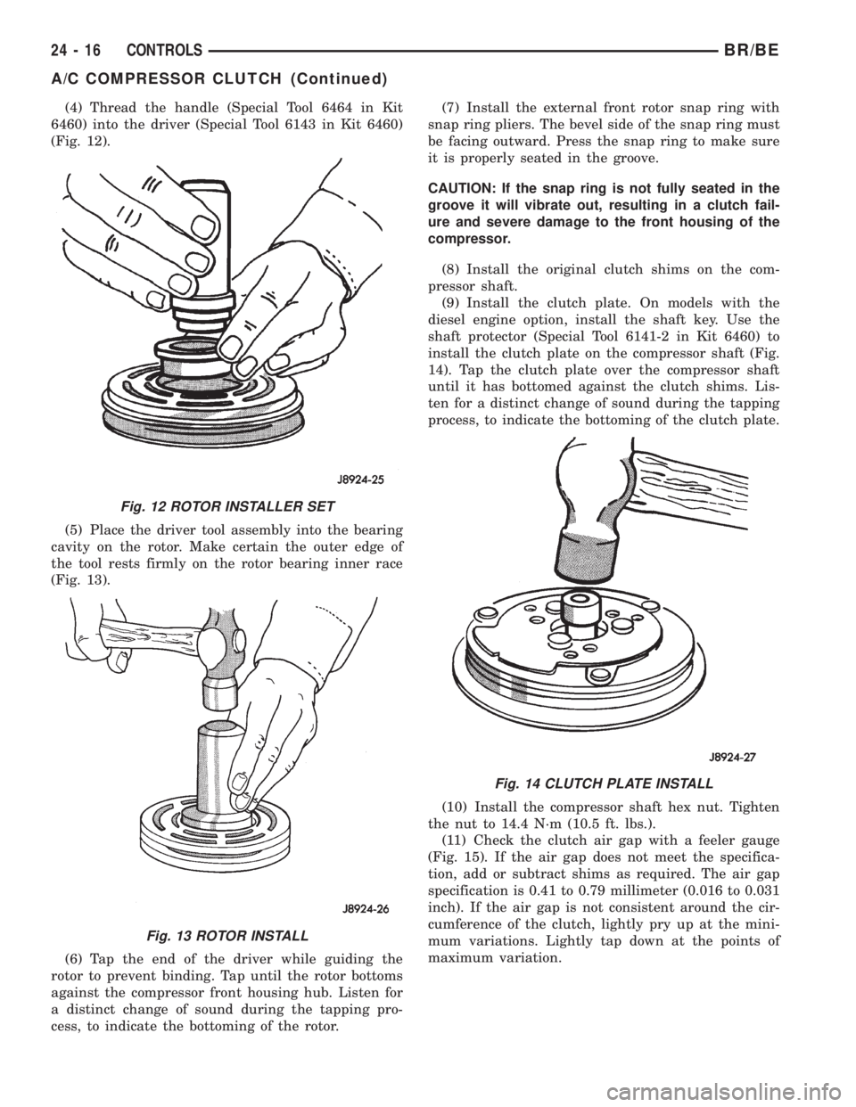
(4) Thread the handle (Special Tool 6464 in Kit
6460) into the driver (Special Tool 6143 in Kit 6460)
(Fig. 12).
(5) Place the driver tool assembly into the bearing
cavity on the rotor. Make certain the outer edge of
the tool rests firmly on the rotor bearing inner race
(Fig. 13).
(6) Tap the end of the driver while guiding the
rotor to prevent binding. Tap until the rotor bottoms
against the compressor front housing hub. Listen for
a distinct change of sound during the tapping pro-
cess, to indicate the bottoming of the rotor.(7) Install the external front rotor snap ring with
snap ring pliers. The bevel side of the snap ring must
be facing outward. Press the snap ring to make sure
it is properly seated in the groove.
CAUTION: If the snap ring is not fully seated in the
groove it will vibrate out, resulting in a clutch fail-
ure and severe damage to the front housing of the
compressor.
(8) Install the original clutch shims on the com-
pressor shaft.
(9) Install the clutch plate. On models with the
diesel engine option, install the shaft key. Use the
shaft protector (Special Tool 6141-2 in Kit 6460) to
install the clutch plate on the compressor shaft (Fig.
14). Tap the clutch plate over the compressor shaft
until it has bottomed against the clutch shims. Lis-
ten for a distinct change of sound during the tapping
process, to indicate the bottoming of the clutch plate.
(10) Install the compressor shaft hex nut. Tighten
the nut to 14.4 N´m (10.5 ft. lbs.).
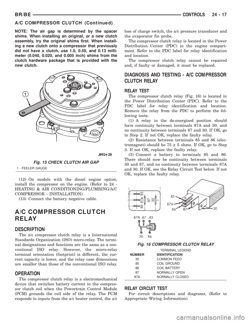
(11) Check the clutch air gap with a feeler gauge
(Fig. 15). If the air gap does not meet the specifica-
tion, add or subtract shims as required. The air gap
specification is 0.41 to 0.79 millimeter (0.016 to 0.031
inch). If the air gap is not consistent around the cir-
cumference of the clutch, lightly pry up at the mini-
mum variations. Lightly tap down at the points of
maximum variation.
Fig. 12 ROTOR INSTALLER SET
Fig. 13 ROTOR INSTALL
Fig. 14 CLUTCH PLATE INSTALL
24 - 16 CONTROLSBR/BE
A/C COMPRESSOR CLUTCH (Continued)
Page 2138 of 2255
NOTE: The air gap is determined by the spacer
shims. When installing an original, or a new clutch
assembly, try the original shims first. When install-
ing a new clutch onto a compressor that previously
did not have a clutch, use 1.0, 0.50, and 0.13 milli-
meter (0.040, 0.020, and 0.005 inch) shims from the
clutch hardware package that is provided with the
new clutch.
(12) On models with the diesel engine option,
install the compressor on the engine. (Refer to 24 -
HEATING & AIR CONDITIONING/PLUMBING/A/C
COMPRESSOR - INSTALLATION)
(13) Connect the battery negative cable.
A/C COMPRESSOR CLUTCH
RELAY
DESCRIPTION
The a/c compressor clutch relay is a International
Standards Organization (ISO) micro-relay. The termi-
nal designations and functions are the same as a con-
ventional ISO relay. However, the micro-relay
terminal orientation (footprint) is different, the cur-
rent capacity is lower, and the relay case dimensions
are smaller than those of the conventional ISO relay.
OPERATION
The compressor clutch relay is a electromechanical
device that switches battery current to the compres-
sor clutch coil when the Powertrain Control Module
(PCM) grounds the coil side of the relay. The PCM
responds to inputs from the a/c heater control, the a/closs of charge switch, the a/c pressure transducer and
the evaporator fin probe.
The compressor clutch relay is located in the Power
Distribution Center (PDC) in the engine compart-
ment. Refer to the PDC label for relay identification
and location.
The compressor clutch relay cannot be repaired
and, if faulty or damaged, it must be replaced.
DIAGNOSIS AND TESTING - A/C COMPRESSOR
CLUTCH RELAY
RELAY TEST
The compressor clutch relay (Fig. 16) is located in
the Power Distribution Center (PDC). Refer to the
PDC label for relay identification and location.
Remove the relay from the PDC to perform the fol-
lowing tests:
(1) A relay in the de-energized position should
have continuity between terminals 87A and 30, and
no continuity between terminals 87 and 30. If OK, go
to Step 2. If not OK, replace the faulty relay.
(2) Resistance between terminals 85 and 86 (elec-
tromagnet) should be 75 5 ohms. If OK, go to Step
3. If not OK, replace the faulty relay.
(3) Connect a battery to terminals 85 and 86.
There should now be continuity between terminals
30 and 87, and no continuity between terminals 87A
and 30. If OK, see the Relay Circuit Test below. If not
OK, replace the faulty relay.
RELAY CIRCUIT TEST
For circuit descriptions and diagrams, (Refer to
Appropriate Wiring Information).
Fig. 15 CHECK CLUTCH AIR GAP
1 - FEELER GAUGE
Fig. 16 COMPRESSOR CLUTCH RELAY
TERMINAL LEGEND
NUMBER IDENTIFICATION
30 COMMON FEED
85 COIL GROUND
86 COIL BATTERY
87 NORMALLY OPEN
87A NORMALLY CLOSED
BR/BECONTROLS 24 - 17
A/C COMPRESSOR CLUTCH (Continued)
Page 2139 of 2255
(1) The relay common feed terminal cavity (30) is
connected to fused battery feed. There should be bat-
tery voltage at the cavity for relay terminal 30 at all
times. If OK, go to Step 2. If not OK, repair the open
circuit to the fuse in the PDC as required.
(2) The relay normally closed terminal (87A) is not
used in this application. Go to Step 3.
(3) The relay normally open terminal cavity (87) is
connected to the compressor clutch coil. There should
be continuity between this cavity and the A/C com-
pressor clutch relay output circuit cavity of the com-
pressor clutch coil wire harness connector. If OK, go
to Step 4. If not OK, repair the open circuit as
required.
(4) The relay coil battery terminal (86) is con-
nected to the fused ignition switch output (run/start)
circuit. There should be battery voltage at the cavity
for relay terminal 86 with the ignition switch in the
On position. If OK, go to Step 5. If not OK, repair the
open circuit to the fuse in the junction block as
required.
(5) The coil ground terminal cavity (85) is switched
to ground through the Powertrain Control Module
(PCM). There should be continuity between this cav-
ity and the A/C compressor clutch relay control cir-
cuit cavity of the PCM wire harness connector C
(gray) at all times. If not OK, repair the open circuit
as required.
REMOVAL
(1) Disconnect and isolate the battery negative
cable.
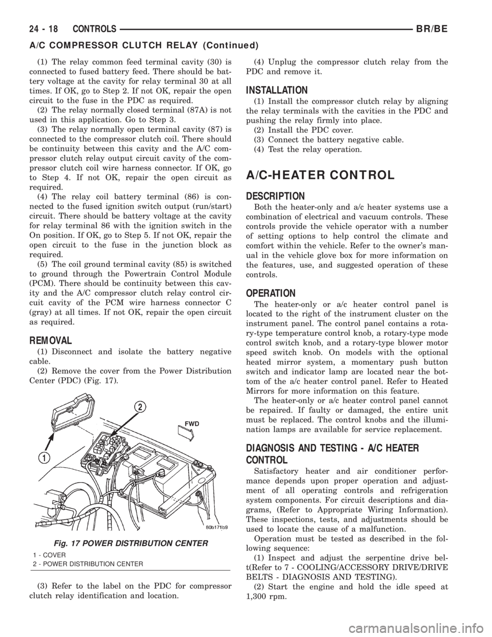
(2) Remove the cover from the Power Distribution
Center (PDC) (Fig. 17).
(3) Refer to the label on the PDC for compressor
clutch relay identification and location.(4) Unplug the compressor clutch relay from the
PDC and remove it.
INSTALLATION
(1) Install the compressor clutch relay by aligning
the relay terminals with the cavities in the PDC and
pushing the relay firmly into place.
(2) Install the PDC cover.
(3) Connect the battery negative cable.
(4) Test the relay operation.
A/C-HEATER CONTROL
DESCRIPTION
Both the heater-only and a/c heater systems use a
combination of electrical and vacuum controls. These
controls provide the vehicle operator with a number
of setting options to help control the climate and
comfort within the vehicle. Refer to the owner's man-
ual in the vehicle glove box for more information on
the features, use, and suggested operation of these
controls.
OPERATION
The heater-only or a/c heater control panel is
located to the right of the instrument cluster on the
instrument panel. The control panel contains a rota-
ry-type temperature control knob, a rotary-type mode
control switch knob, and a rotary-type blower motor
speed switch knob. On models with the optional
heated mirror system, a momentary push button
switch and indicator lamp are located near the bot-
tom of the a/c heater control panel. Refer to Heated
Mirrors for more information on this feature.
The heater-only or a/c heater control panel cannot
be repaired. If faulty or damaged, the entire unit
must be replaced. The control knobs and the illumi-
nation lamps are available for service replacement.
DIAGNOSIS AND TESTING - A/C HEATER
CONTROL
Satisfactory heater and air conditioner perfor-
mance depends upon proper operation and adjust-
ment of all operating controls and refrigeration
system components. For circuit descriptions and dia-
grams, (Refer to Appropriate Wiring Information).
These inspections, tests, and adjustments should be
used to locate the cause of a malfunction.
Operation must be tested as described in the fol-
lowing sequence:
(1) Inspect and adjust the serpentine drive bel-
t(Refer to 7 - COOLING/ACCESSORY DRIVE/DRIVE
BELTS - DIAGNOSIS AND TESTING).
(2) Start the engine and hold the idle speed at
1,300 rpm.
Fig. 17 POWER DISTRIBUTION CENTER
1 - COVER
2 - POWER DISTRIBUTION CENTER
24 - 18 CONTROLSBR/BE
A/C COMPRESSOR CLUTCH RELAY (Continued)
Page 2141 of 2255
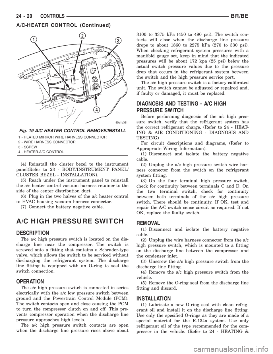
(4) Reinstall the cluster bezel to the instrument
panel(Refer to 23 - BODY/INSTRUMENT PANEL/
CLUSTER BEZEL - INSTALLATION).
(5) Reach under the instrument panel to reinstall
the a/c heater control vacuum harness retainer to the
side of the center distribution duct.
(6) Plug in the two halves of the a/c heater control
to HVAC housing vacuum harness connector.
(7) Connect the battery negative cable.
A/C HIGH PRESSURE SWITCH
DESCRIPTION
The a/c high pressure switch is located on the dis-
charge line near the compressor. The switch is
screwed onto a fitting that contains a Schrader-type
valve, which allows the switch to be serviced without
discharging the refrigerant system. The discharge
line fitting is equipped with an O-ring to seal the
switch connection.
OPERATION
The a/c high pressure switch is connected in series
electrically with the a/c low pressure switch between
ground and the Powertrain Control Module (PCM).
The switch contacts open and close causing the PCM
to turn the compressor clutch on and off. This pre-
vents compressor operation when the discharge line
pressure approaches high levels.
The a/c high pressure switch contacts are open
when the discharge line pressure rises above about3100 to 3375 kPa (450 to 490 psi). The switch con-
tacts will close when the discharge line pressure
drops to about 1860 to 2275 kPa (270 to 330 psi).
When checking refrigerant system pressures with a
manifold gauge set, keep in mind that the indicated
pressures will be about 172 kpa (25 psi) below the
actual switch pressure values due to the pressure
drop that occurs in the refrigerant system between
the switch and the high pressure service port.
The a/c high pressure switch is a factory-calibrated
unit. The switch cannot be adjusted or repaired and,
if faulty or damaged, it must be replaced.
DIAGNOSIS AND TESTING - A/C HIGH
PRESSURE SWITCH
Before performing diagnosis of the a/c high pres-
sure switch, verify that the refrigerant system has
the correct refrigerant charge. (Refer to 24 - HEAT-
ING & AIR CONDITIONING - DIAGNOSIS AND
TESTING)
For circuit descriptions and diagrams, (Refer to
Appropriate Wiring Information).
(1) Disconnect and isolate the battery negative
cable.
(2) Unplug the a/c high pressure switch wire har-
ness connector from the switch on the refrigerant
system fitting.
(3) On the four terminal high pressure switch,
check for continuity between terminals C and D. On
the two terminal switch, check for continuity
between both terminals of the a/c high pressure
switch. There should be continuity. If OK, test and
repair the A/C switch sense circuit as required. If not
OK, replace the faulty switch.
REMOVAL
(1) Disconnect and isolate the battery negative
cable.
(2) Unplug the wire harness connector from the a/c
high pressure switch, which is mounted to a fitting
on the discharge line between the compressor and
the condenser inlet.
(3) Unscrew the a/c high pressure switch from the
discharge line fitting.
(4) Remove the a/c high pressure switch from the
vehicle.
(5) Remove the O-ring seal from the discharge line
fitting and discard.
INSTALLATION
(1) Lubricate a new O-ring seal with clean refrig-
erant oil and install it on the discharge line fitting.
Use only the specified O-rings as they are made of a
special material for the R-134a system. Use only
refrigerant oil of the type recommended for the com-
pressor in the vehicle. (Refer to 24 - HEATING &
Fig. 19 A/C HEATER CONTROL REMOVE/INSTALL
1 - HEATED MIRROR WIRE HARNESS CONNECTOR
2 - WIRE HARNESS CONNECTOR
3 - SCREW
4 - HEATER-A/C CONTROL
24 - 20 CONTROLSBR/BE
A/C-HEATER CONTROL (Continued)
Page 2142 of 2255
AIR CONDITIONING/PLUMBING/REFRIGERANT
OIL - DESCRIPTION)
(2) Install and tighten the high pressure cut-off
switch on the discharge line fitting. The switch
should be hand-tightened onto the discharge line fit-
ting.
(3) Plug the wire harness connector into the high
pressure cut-off switch.
(4) Connect the battery negative cable.
A/C LOW PRESSURE SWITCH
DESCRIPTION
The a/c low pressure switch is located on the top of
the accumulator. The switch is screwed onto an accu-
mulator fitting that contains a Schrader-type valve,
which allows the switch to be serviced without dis-
charging the refrigerant system. The accumulator fit-
ting is equipped with an O-ring to seal the switch
connection.
OPERATION
The a/c low pressure switch is connected in series
electrically with the a/c high pressure switch and the
a/c heater control, between ground and the Power-
train Control Module (PCM). The switch contacts
open and close causing the PCM to turn the compres-
sor clutch on and off. This regulates the refrigerant
system pressure and controls evaporator tempera-
ture. Controlling evaporator temperature prevents
condensate water on the evaporator fins from freez-
ing and obstructing air conditioning system air flow.
The a/c low pressure switch contacts are open
when the suction pressure is about 152-165 kPa
(22-24 psi) or lower. The switch contacts will close
when the suction pressure rises to about 255-296 kPa
(37-43 psi) or above. Lower ambient temperatures,
below about -1É C (30É F), will also cause the switch
contacts to open. This is due to the pressure/temper-
ature relationship of the refrigerant in the system.
The a/c low pressure switch is a factory-calibrated
unit. It cannot be adjusted or repaired and, if faulty
or damaged, it must be replaced.
DIAGNOSIS AND TESTING - A/C LOW
PRESSURE SWITCH
Before performing diagnosis of the a/c low pressure
switch, be certain that the switch is properly
installed on the accumulator fitting. If the switch is
too loose it may not open the Schrader-type valve in
the accumulator fitting, which will prevent the
switch from correctly monitoring the refrigerant sys-
tem pressure. Also verify that the refrigerant system
has the correct refrigerant charge. (Refer to 24 -HEATING & AIR CONDITIONING - DIAGNOSIS
AND TESTING - A/C PERFORMANCE)
Remember that lower ambient temperatures, below
about -1É C (30É F), during cold weather will open the
switch contacts and prevent compressor operation
due to the pressure/temperature relationship of the
refrigerant. For circuit descriptions and diagrams,
(Refer to Appropriate Wiring Information).
(1) Disconnect and isolate the battery negative
cable.
(2) Unplug the a/c low pressure switch wire har-
ness connector from the switch on the accumulator
fitting.
(3) Install a jumper wire between the two cavities
of the a/c low pressure switch wire harness connector.
(4) Connect a manifold gauge set to the refrigerant
system service ports. (Refer to 24 - HEATING & AIR
CONDITIONING/PLUMBING - STANDARD PRO-
CEDURE - REFRIGERANT SYSTEM SERVICE
EQUIPMENT)
(5) Connect the battery negative cable.
(6) Place the a/c heater mode control switch knob
in any A/C position and start the engine.
(7) Check for continuity between the two terminals
of the low pressure cycling clutch switch. There
should be continuity with a suction pressure reading
of 296 kPa (43 psi) or above, and no continuity with a
suction pressure reading of 172 kPa (25 psi) or below.
If OK, test and repair the A/C switch sense circuit as
required. If not OK, replace the faulty switch.
REMOVAL
(1) Disconnect and isolate the battery negative
cable.
(2) Unplug the wire harness connector from the a/c
low pressure switch on the top of the accumulator
(Fig. 20).
(3) Unscrew the a/c low pressure switch from the
fitting on the top of the accumulator.
(4) Remove the O-ring seal from the accumulator
fitting and discard.
INSTALLATION
(1) Lubricate a new O-ring seal with clean refrig-
erant oil and install it on the accumulator fitting.
Use only the specified O-rings as they are made of a
special material for the R-134a system. Use only
refrigerant oil of the type recommended for the com-
pressor in the vehicle. (Refer to 24 - HEATING &
AIR CONDITIONING/PLUMBING/REFRIGERANT
OIL - DESCRIPTION)
(2) Install and tighten the a/c low pressure switch
on the accumulator fitting. The switch should be
hand-tightened onto the accumulator fitting.
(3) Plug the wire harness connector into the a/c
low pressure switch.
BR/BECONTROLS 24 - 21
A/C HIGH PRESSURE SWITCH (Continued)
Page 2161 of 2255
PLUMBING
TABLE OF CONTENTS
page page
PLUMBING
DESCRIPTION..........................40
OPERATION............................41
WARNING..............................42
CAUTION..............................42
DIAGNOSIS AND TESTING
DIAGNOSIS AND TESTING - REFRIGERANT
SYSTEM LEAKS.......................43
STANDARD PROCEDURE
STANDARD PROCEDURE - A/C LINE
COUPLERS...........................44
STANDARD PROCEDURE - REFRIGERANT
SYSTEM SERVICE EQUIPMENT...........45
STANDARD PROCEDURE - REFRIGERANT
RECOVERY...........................45
STANDARD PROCEDURE - REFRIGERANT
SYSTEM EVACUATE....................46
STANDARD PROCEDURE - REFRIGERANT
SYSTEM CHARGE......................46
SPECIFICATIONS........................46
A/C COMPRESSOR
DESCRIPTION..........................46
OPERATION............................46
DIAGNOSIS AND TESTING
DIAGNOSIS AND TESTING - A/C
COMPRESSOR........................47
REMOVAL..............................47
INSTALLATION..........................48
A/C CONDENSER
DESCRIPTION..........................49
OPERATION............................49
REMOVAL..............................49
INSTALLATION..........................50
SUCTION AND DISCHARGE LINE
REMOVAL..............................51
INSTALLATION..........................52LIQUID LINE
REMOVAL..............................52
INSTALLATION..........................52
A/C EVAPORATOR
DESCRIPTION..........................53
OPERATION............................53
REMOVAL..............................53
INSTALLATION..........................53
A/C ORIFICE TUBE
DESCRIPTION..........................54
OPERATION............................54
DIAGNOSIS AND TESTING
DIAGNOSIS AND TESTING - FIXED
ORIFICE TUBE.........................54
REMOVAL..............................54
INSTALLATION..........................54
ACCUMULATOR
DESCRIPTION..........................55
OPERATION............................55
REMOVAL..............................55
INSTALLATION..........................55
HEATER CORE
DESCRIPTION..........................56
OPERATION............................56
REMOVAL..............................56
INSTALLATION..........................56
REFRIGERANT
DESCRIPTION..........................56
OPERATION............................57
REFRIGERANT OIL
DESCRIPTION..........................57
OPERATION............................57
STANDARD PROCEDURE
STANDARD PROCEDURE - REFRIGERANT
OIL LEVEL............................57
PLUMBING
DESCRIPTION - A/C LINE COUPLERS
Spring-lock type refrigerant line couplers are used
to connect many of the refrigerant lines and other
components to the refrigerant system. These couplers
require a special tool for disengaging the two coupler
halves.
DESCRIPTION- REFRIGERANT LINES
The refrigerant lines and hoses are used to carry
the refrigerant between the various air conditioning
system components. A barrier hose design with a
nylon tube, which is sandwiched between rubber lay-
ers, is used for the R-134a air conditioning system on
this vehicle. This nylon tube helps to further contain
the R-134a refrigerant, which has a smaller molecu-
lar structure than R-12 refrigerant. The ends of the
refrigerant hoses are made from lightweight alumi-
num or steel, and commonly use braze-less fittings.
24 - 40 PLUMBINGBR/BE
Page 2162 of 2255
Any kinks or sharp bends in the refrigerant plumb-
ing will reduce the capacity of the entire air condi-
tioning system. Kinks and sharp bends reduce the
flow of refrigerant in the system. A good rule for the
flexible hose refrigerant lines is to keep the radius of
all bends at least ten times the diameter of the hose.
In addition, the flexible hose refrigerant lines should
be routed so they are at least 80 millimeters (3
inches) from the exhaust manifold.
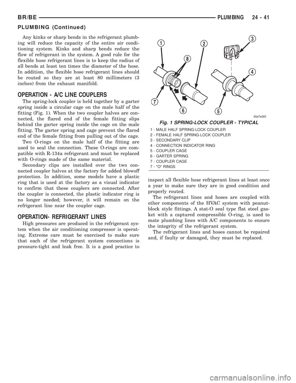
OPERATION - A/C LINE COUPLERS
The spring-lock coupler is held together by a garter
spring inside a circular cage on the male half of the
fitting (Fig. 1). When the two coupler halves are con-
nected, the flared end of the female fitting slips
behind the garter spring inside the cage on the male
fitting. The garter spring and cage prevent the flared
end of the female fitting from pulling out of the cage.
Two O-rings on the male half of the fitting are
used to seal the connection. These O-rings are com-
patible with R-134a refrigerant and must be replaced
with O-rings made of the same material.
Secondary clips are installed over the two con-
nected coupler halves at the factory for added blowoff
protection. In addition, some models have a plastic
ring that is used at the factory as a visual indicator
to confirm that these couplers are connected. After
the coupler is connected, the plastic indicator ring is
no longer needed; however, it will remain on the
refrigerant line near the coupler cage.
OPERATION- REFRIGERANT LINES
High pressures are produced in the refrigerant sys-
tem when the air conditioning compressor is operat-
ing. Extreme care must be exercised to make sure
that each of the refrigerant system connections is
pressure-tight and leak free. It is a good practice toinspect all flexible hose refrigerant lines at least once
a year to make sure they are in good condition and
properly routed.
The refrigerant lines and hoses are coupled with
other components of the HVAC system with peanut-
block style fittings. A stat-O seal type flat steel gas-
ket with a captured compressible O-ring, is used to
mate plumbing lines with A/C components to ensure
the integrity of the refrigerant system.
The refrigerant lines and hoses cannot be repaired
and, if faulty or damaged, they must be replaced.
Fig. 1 SPRING-LOCK COUPLER - TYPICAL
1 - MALE HALF SPRING-LOCK COUPLER
2 - FEMALE HALF SPRING-LOCK COUPLER
3 - SECONDARY CLIP
4 - CONNECTION INDICATOR RING
5 - COUPLER CAGE
6 - GARTER SPRING
7 - COUPLER CAGE
7-9O9RINGS
BR/BEPLUMBING 24 - 41
PLUMBING (Continued)
Page 2163 of 2255
SERVICE WARNINGS
WARNING:
THE AIR CONDITIONING SYSTEM CONTAINS
REFRIGERANT UNDER HIGH PRESSURE. SEVERE
PERSONAL INJURY MAY RESULT FROM IMPROPER
SERVICE PROCEDURES. REPAIRS SHOULD ONLY
BE PERFORMED BY QUALIFIED SERVICE PERSON-
NEL.
AVOID BREATHING THE REFRIGERANT AND
REFRIGERANT OIL VAPOR OR MIST. EXPOSURE
MAY IRRITATE THE EYES, NOSE, AND/OR THROAT.
WEAR EYE PROTECTION WHEN SERVICING THE
AIR CONDITIONING REFRIGERANT SYSTEM. SERI-
OUS EYE INJURY CAN RESULT FROM DIRECT
CONTACT WITH THE REFRIGERANT. IF EYE CON-
TACT OCCURS, SEEK MEDICAL ATTENTION IMME-
DIATELY.
DO NOT EXPOSE THE REFRIGERANT TO OPEN
FLAME. POISONOUS GAS IS CREATED WHEN
REFRIGERANT IS BURNED. AN ELECTRONIC LEAK
DETECTOR IS RECOMMENDED.
IF ACCIDENTAL SYSTEM DISCHARGE OCCURS,
VENTILATE THE WORK AREA BEFORE RESUMING
SERVICE. LARGE AMOUNTS OF REFRIGERANT
RELEASED IN A CLOSED WORK AREA WILL DIS-
PLACE THE OXYGEN AND CAUSE SUFFOCATION.
THE EVAPORATION RATE OF R-134a REFRIGER-
ANT AT AVERAGE TEMPERATURE AND ALTITUDE
IS EXTREMELY HIGH. AS A RESULT, ANYTHING
THAT COMES IN CONTACT WITH THE REFRIGER-
ANT WILL FREEZE. ALWAYS PROTECT THE SKIN
OR DELICATE OBJECTS FROM DIRECT CONTACT
WITH THE REFRIGERANT.
THE R-134a SERVICE EQUIPMENT OR THE VEHI-
CLE REFRIGERANT SYSTEM SHOULD NOT BE
PRESSURE TESTED OR LEAK TESTED WITH COM-
PRESSED AIR. SOME MIXTURES OF AIR AND
R-134a HAVE BEEN SHOWN TO BE COMBUSTIBLE
AT ELEVATED PRESSURES. THESE MIXTURES ARE
POTENTIALLY DANGEROUS, AND MAY RESULT IN
FIRE OR EXPLOSION CAUSING INJURY OR PROP-
ERTY DAMAGE.
SERVICE CAUTIONS
CAUTION: Liquid refrigerant is corrosive to metal
surfaces. Follow the operating instructions supplied
with the service equipment being used.
Never add R-12 to a refrigerant system designed to
use R-134a. Damage to the system will result.
R-12 refrigerant oil must not be mixed with R-134a
refrigerant oil. They are not compatible.
Do not use R-12 equipment or parts on the R-134a
system. Damage to the system will result.Do not overcharge the refrigerant system. This will
cause excessive compressor head pressure and
can cause noise and system failure.
Recover the refrigerant before opening any fitting
or connection. Open the fittings with caution, even
after the system has been discharged. Never open
or loosen a connection before recovering the refrig-
erant.
Do not remove the secondary retention clip from
any spring-lock coupler connection while the refrig-
erant system is under pressure. Recover the refrig-
erant before removing the secondary retention clip.
Open the fittings with caution, even after the sys-
tem has been discharged. Never open or loosen a
connection before recovering the refrigerant.
The refrigerant system must always be evacuated
before charging.
Do not open the refrigerant system or uncap a
replacement component until you are ready to ser-
vice the system. This will prevent contamination in
the system.
Before disconnecting a component, clean the out-
side of the fittings thoroughly to prevent contami-
nation from entering the refrigerant system.
Immediately after disconnecting a component from
the refrigerant system, seal the open fittings with a
cap or plug.
Before connecting an open refrigerant fitting,
always install a new seal or gasket. Coat the fitting
and seal with clean refrigerant oil before connect-
ing.
Do not remove the sealing caps from a replacement
component until it is to be installed.
When installing a refrigerant line, avoid sharp
bends that may restrict refrigerant flow. Position the
refrigerant lines away from exhaust system compo-
nents or any sharp edges, which may damage the
line.
Tighten refrigerant fittings only to the specified
torque. The aluminum fittings used in the refriger-
ant system will not tolerate overtightening.
When disconnecting a refrigerant fitting, use a
wrench on both halves of the fitting. This will pre-
vent twisting of the refrigerant lines or tubes.
Refrigerant oil will absorb moisture from the atmo-
sphere if left uncapped. Do not open a container of
refrigerant oil until you are ready to use it. Replace
the cap on the oil container immediately after using.
Store refrigerant oil only in a clean, airtight, and
moisture-free container.
Keep service tools and the work area clean. Con-
tamination of the refrigerant system through care-
less work habits must be avoided.
24 - 42 PLUMBINGBR/BE
PLUMBING (Continued)