2002 DODGE RAM air condition
[x] Cancel search: air conditionPage 393 of 2255
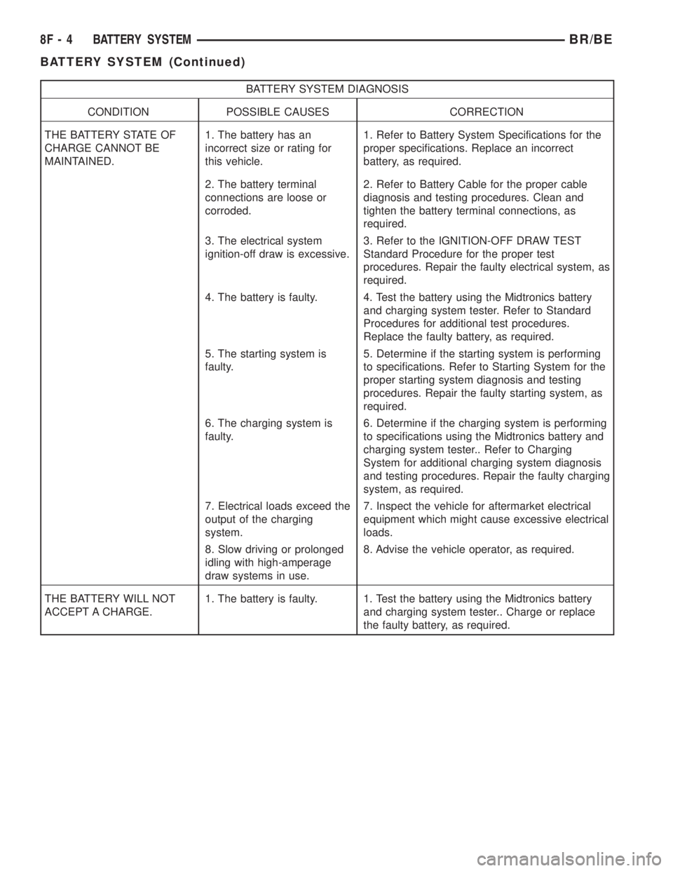
BATTERY SYSTEM DIAGNOSIS
CONDITION POSSIBLE CAUSES CORRECTION
THE BATTERY STATE OF
CHARGE CANNOT BE
MAINTAINED.1. The battery has an
incorrect size or rating for
this vehicle.1. Refer to Battery System Specifications for the
proper specifications. Replace an incorrect
battery, as required.
2. The battery terminal
connections are loose or
corroded.2. Refer to Battery Cable for the proper cable
diagnosis and testing procedures. Clean and
tighten the battery terminal connections, as
required.
3. The electrical system
ignition-off draw is excessive.3. Refer to the IGNITION-OFF DRAW TEST
Standard Procedure for the proper test
procedures. Repair the faulty electrical system, as
required.
4. The battery is faulty. 4. Test the battery using the Midtronics battery
and charging system tester. Refer to Standard
Procedures for additional test procedures.
Replace the faulty battery, as required.
5. The starting system is
faulty.5. Determine if the starting system is performing
to specifications. Refer to Starting System for the
proper starting system diagnosis and testing
procedures. Repair the faulty starting system, as
required.
6. The charging system is
faulty.6. Determine if the charging system is performing
to specifications using the Midtronics battery and
charging system tester.. Refer to Charging
System for additional charging system diagnosis
and testing procedures. Repair the faulty charging
system, as required.
7. Electrical loads exceed the
output of the charging
system.7. Inspect the vehicle for aftermarket electrical
equipment which might cause excessive electrical
loads.
8. Slow driving or prolonged
idling with high-amperage
draw systems in use.8. Advise the vehicle operator, as required.
THE BATTERY WILL NOT
ACCEPT A CHARGE.1. The battery is faulty. 1. Test the battery using the Midtronics battery
and charging system tester.. Charge or replace
the faulty battery, as required.
8F - 4 BATTERY SYSTEMBR/BE
BATTERY SYSTEM (Continued)
Page 415 of 2255
²a faulty or improperly adjusted switch that
allows a lamp to stay on. Refer to Ignition-Off Draw
Test in 8, Battery for more information.
INSPECTION
The Powertrain Control Module (PCM) monitors
critical input and output circuits of the charging sys-
tem, making sure they are operational. A Diagnostic
Trouble Code (DTC) is assigned to each input and
output circuit monitored by the On-Board Diagnostic
(OBD) system. Some charging system circuits are
checked continuously, and some are checked only
under certain conditions.
Refer to Diagnostic Trouble Codes in; Powertrain
Control Module; Electronic Control Modules for more
DTC information. This will include a complete list of
DTC's including DTC's for the charging system.
To perform a complete test of the charging system,
refer to the appropriate Powertrain Diagnostic Proce-
dures service manual and the DRBtscan tool. Per-
form the following inspections before attaching the
scan tool.
(1) Inspect the battery condition. Refer to 8, Bat-
tery for procedures.(2) Inspect condition of battery cable terminals,
battery posts, connections at engine block, starter
solenoid and relay. They should be clean and tight.
Repair as required.
(3) Inspect all fuses in both the fuseblock and
Power Distribution Center (PDC) for tightness in
receptacles. They should be properly installed and
tight. Repair or replace as required.
(4) Inspect generator mounting bolts for tightness.
Replace or tighten bolts if required. Refer to the Gen-
erator Removal/Installation section of this group for
torque specifications.
(5) Inspect generator drive belt condition and ten-
sion. Tighten or replace belt as required. Refer to
Belt Tension Specifications in 7, Cooling System.
(6) Inspect automatic belt tensioner (if equipped).
Refer to 7, Cooling System for information.
(7) Inspect generator electrical connections at gen-
erator field, battery output, and ground terminal (if
equipped). Also check generator ground wire connec-
tion at engine (if equipped). They should all be clean
and tight. Repair as required.
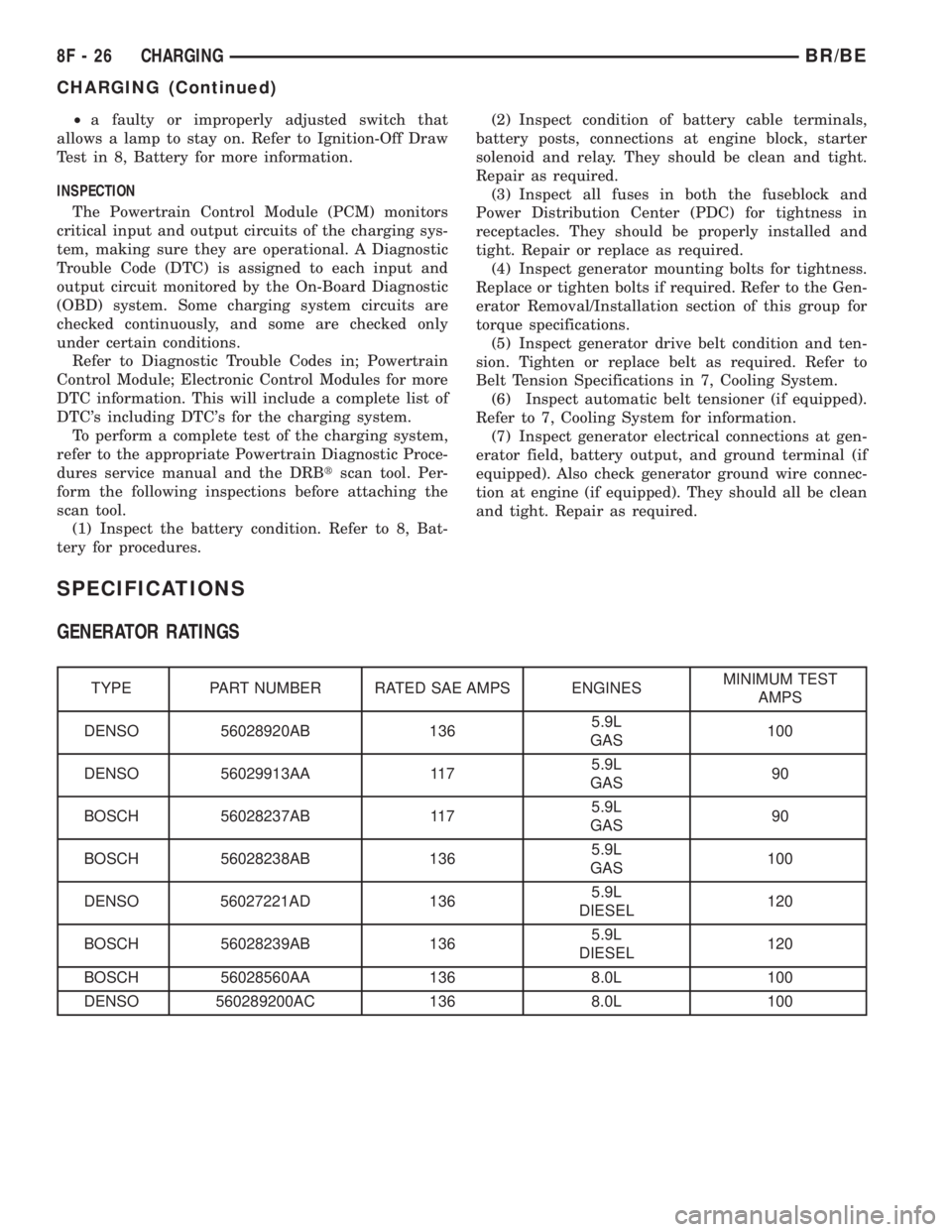
SPECIFICATIONS
GENERATOR RATINGS
TYPE PART NUMBER RATED SAE AMPS ENGINESMINIMUM TEST
AMPS
DENSO 56028920AB 1365.9L
GAS100
DENSO 56029913AA 1175.9L
GAS90
BOSCH 56028237AB 1175.9L
GAS90
BOSCH 56028238AB 1365.9L
GAS100
DENSO 56027221AD 1365.9L
DIESEL120
BOSCH 56028239AB 1365.9L
DIESEL120
BOSCH 56028560AA 136 8.0L 100
DENSO 560289200AC 136 8.0L 100
8F - 26 CHARGINGBR/BE
CHARGING (Continued)
Page 421 of 2255
This normally open switch prevents the starter relay
from being energized and the starter motor from
operating unless the automatic transmission gear
selector is in the Neutral or Park positions.
When the starter relay coil is energized, the nor-
mally open relay contacts close. The relay contacts
connect the relay common feed terminal to the relay
normally open terminal. The closed relay contacts
energize the starter solenoid coil windings.
The energized solenoid pull-in coil pulls in the sole-
noid plunger. The solenoid plunger pulls the shift
lever in the starter motor. This engages the starter
overrunning clutch and pinion gear with the starter
ring gear on the manual transmission flywheel or on
the automatic transmission torque converter or
torque converter drive plate.
As the solenoid plunger reaches the end of its
travel, the solenoid contact disc completes the high-
amperage starter feed circuit and energizes the sole-
noid plunger hold-in coil. Current now flows between
the solenoid battery terminal and the starter motor,
energizing the starter.
Once the engine starts, the overrunning clutch pro-
tects the starter motor from damage by allowing thestarter pinion gear to spin faster than the pinion
shaft. When the driver releases the ignition switch to
the On position, the starter relay coil is de-energized.
This causes the relay contacts to open. When the
relay contacts open, the starter solenoid plunger
hold-in coil is de-energized.
When the solenoid plunger hold-in coil is de-ener-
gized, the solenoid plunger return spring returns the
plunger to its relaxed position. This causes the con-
tact disc to open the starter feed circuit, and the shift
lever to disengage the overrunning clutch and pinion
gear from the starter ring gear.
DIAGNOSIS AND TESTING - STARTING
SYSTEM
The battery, starting, and charging systems oper-
ate in conjunction with one another, and must be
tested as a complete system. For correct starting/
charging system operation, all of the components
involved in these 3 systems must perform within
specifications.
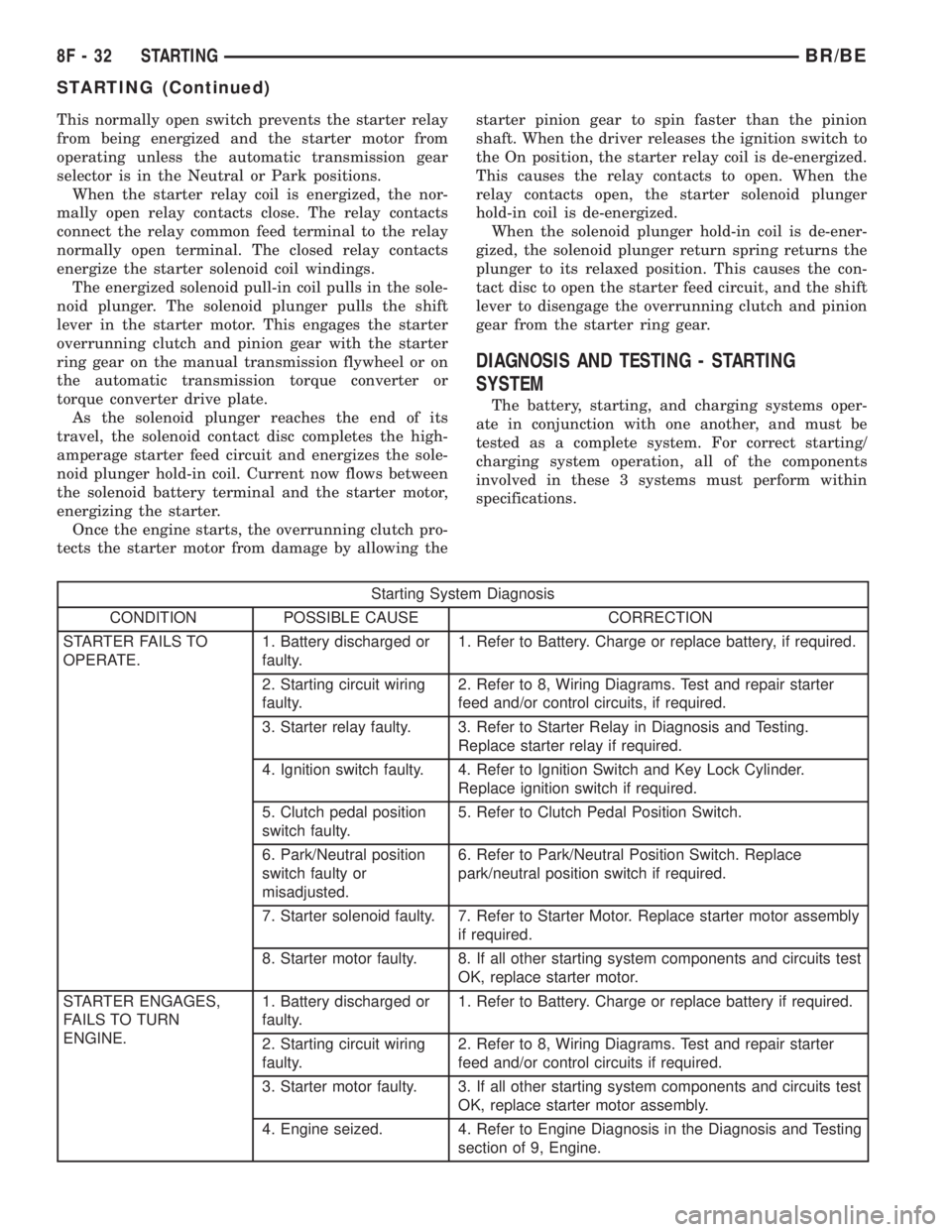
Starting System Diagnosis
CONDITION POSSIBLE CAUSE CORRECTION
STARTER FAILS TO
OPERATE.1. Battery discharged or
faulty.1. Refer to Battery. Charge or replace battery, if required.
2. Starting circuit wiring
faulty.2. Refer to 8, Wiring Diagrams. Test and repair starter
feed and/or control circuits, if required.
3. Starter relay faulty. 3. Refer to Starter Relay in Diagnosis and Testing.
Replace starter relay if required.
4. Ignition switch faulty. 4. Refer to Ignition Switch and Key Lock Cylinder.
Replace ignition switch if required.
5. Clutch pedal position
switch faulty.5. Refer to Clutch Pedal Position Switch.
6. Park/Neutral position
switch faulty or
misadjusted.6. Refer to Park/Neutral Position Switch. Replace
park/neutral position switch if required.
7. Starter solenoid faulty. 7. Refer to Starter Motor. Replace starter motor assembly
if required.
8. Starter motor faulty. 8. If all other starting system components and circuits test
OK, replace starter motor.
STARTER ENGAGES,
FAILS TO TURN
ENGINE.1. Battery discharged or
faulty.1. Refer to Battery. Charge or replace battery if required.
2. Starting circuit wiring
faulty.2. Refer to 8, Wiring Diagrams. Test and repair starter
feed and/or control circuits if required.
3. Starter motor faulty. 3. If all other starting system components and circuits test
OK, replace starter motor assembly.
4. Engine seized. 4. Refer to Engine Diagnosis in the Diagnosis and Testing
section of 9, Engine.
8F - 32 STARTINGBR/BE
STARTING (Continued)
Page 422 of 2255
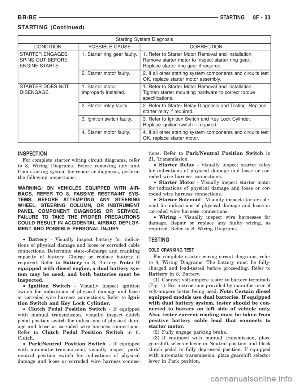
Starting System Diagnosis
CONDITION POSSIBLE CAUSE CORRECTION
STARTER ENGAGES,
SPINS OUT BEFORE
ENGINE STARTS.1. Starter ring gear faulty. 1. Refer to Starter Motor Removal and Installation.
Remove starter motor to inspect starter ring gear.
Replace starter ring gear if required.
2. Starter motor faulty. 2. If all other starting system components and circuits test
OK, replace starter motor assembly.
STARTER DOES NOT
DISENGAGE.1. Starter motor
improperly installed.1. Refer to Starter Motor Removal and Installation.
Tighten starter mounting hardware to correct torque
specifications.
2. Starter relay faulty. 2. Refer to Starter Relay Diagnosis and Testing. Replace
starter relay if required.
3. Ignition switch faulty. 3. Refer to Ignition Switch and Key Lock Cylinder.
Replace ignition switch if required.
4. Starter motor faulty. 4. If all other starting system components and circuits test
OK, replace starter motor.
INSPECTION
For complete starter wiring circuit diagrams, refer
to 8, Wiring Diagrams. Before removing any unit
from starting system for repair or diagnosis, perform
the following inspections:
WARNING: ON VEHICLES EQUIPPED WITH AIR-
BAGS, REFER TO 8, PASSIVE RESTRAINT SYS-
TEMS, BEFORE ATTEMPTING ANY STEERING
WHEEL, STEERING COLUMN, OR INSTRUMENT
PANEL COMPONENT DIAGNOSIS OR SERVICE.
FAILURE TO TAKE THE PROPER PRECAUTIONS
COULD RESULT IN ACCIDENTAL AIRBAG DEPLOY-
MENT AND POSSIBLE PERSONAL INJURY.
²Battery- Visually inspect battery for indica-
tions of physical damage and loose or corroded cable
connections. Determine state-of-charge and cranking
capacity of battery. Charge or replace battery if
required. Refer toBatteryin 8, Battery.Note: If
equipped with diesel engine, a dual battery sys-
tem may be used, and both batteries must be
inspected.
²Ignition Switch- Visually inspect ignition
switch for indications of physical damage and loose
or corroded wire harness connections. Refer toIgni-
tion Switch and Key Lock Cylinder.
²Clutch Pedal Position Switch- If equipped
with manual transmission, visually inspect clutch
pedal position switch for indications of physical dam-
age and loose or corroded wire harness connections.
Refer toClutch Pedal Position Switchin 6,
Clutch.
²Park/Neutral Position Switch- If equipped
with automatic transmission, visually inspect park/
neutral position switch for indications of physical
damage and loose or corroded wire harness connec-tions. Refer toPark/Neutral Position Switchin
21, Transmission.
²Starter Relay- Visually inspect starter relay
for indications of physical damage and loose or cor-
roded wire harness connections.
²Starter Motor- Visually inspect starter motor
for indications of physical damage and loose or cor-
roded wire harness connections.
²Starter Solenoid- Visually inspect starter sole-
noid for indications of physical damage and loose or
corroded wire harness connections.
²Wiring- Visually inspect wire harnesses for
damage. Repair or replace any faulty wiring, as
required. Refer to 8, Wiring Diagrams.
TESTING
COLD CRANKING TEST
For complete starter wiring circuit diagrams, refer
to 8, Wiring Diagrams. The battery must be fully-
charged and load-tested before proceeding. Refer to
Batteryin 8, Battery.
(1) Connect volt-ampere tester to battery terminals
(Fig. 1). See instructions provided by manufacturer of
volt-ampere tester being used.Note: Certain diesel
equipped models use dual batteries. If equipped
with dual battery system, tester should be con-
nected to battery on left side of vehicle only.
Also, tester current reading must be taken from
positive battery cable lead that connects to
starter motor.
(2) Fully engage parking brake.
(3) If equipped with manual transmission, place
gearshift selector lever in Neutral position and block
clutch pedal in fully depressed position. If equipped
with automatic transmission, place gearshift selector
lever in Park position.
BR/BESTARTING 8F - 33
STARTING (Continued)
Page 434 of 2255

tem indicator lamp are visible in the lower left corner
of the a/c heater control face plate (Fig. 2).
The heated mirror switch, the heated mirror sys-
tem indicator lamp, the heated mirror system solid
state electronic control logic and timer circuitry and
the heated mirror relay cannot be repaired. If any of
these components is damaged or faulty, the entire a/c
heater control must be replaced. (Refer to 24 - HEAT-
ING & AIR CONDITIONING/CONTROLS/A/C
HEATER CONTROL - REMOVAL)
OPERATION
The momentary-type heated mirror switch provides
a hard-wired battery current signal to the heated
mirror system electronic control logic circuitry each
time it is depressed. In response to the heated mirror
switch input, the electronic control logic and timer
circuitry energizes or de-energizes the amber heated
mirror system indicator lamp next to the heated mir-
ror switch to indicate that the heated mirror system
is turned On or Off. The electronic control logic and
timer circuitry also energizes or de-energizes the
heated mirror relay, which controls the feed of elec-
trical current to the outside mirror heating grids.
The heated mirror system electronic control logic
and timer circuitry is programmed to turn the heated
mirror system Off automatically after about fifteen
minutes of operation. If the heated mirror system is
turned On a second time following an initial time-out
event during the same ignition switch cycle, the
heated mirror system electronic control logic and
timer circuit is programmed to turn the system Offautomatically after about five minutes. When the
electronic control logic and timer circuit detects that
a programmed time interval has elapsed, it will auto-
matically de-energize the heated mirror system indi-
cator lamp and the heated mirror relay. The heated
mirror system will also be turned Off if the heated
mirror switch is depressed while the system is
turned On, or if the ignition switch is turned to the
Off or Accessory positions.
DIAGNOSIS AND TESTING - HEATED MIRROR
SWITCH
The heated mirror switch, the solid state electronic
heated mirror system control logic and timer cir-
cuitry, the heated mirror system indicator lamp and
the heated mirror relay are all integral to the a/c
heater control. For circuit descriptions and diagrams
(Refer to Appropriate Wiring Information).
WARNING: ON VEHICLES EQUIPPED WITH AIR-
BAGS, DISABLE THE AIRBAG SYSTEM BEFORE
ATTEMPTING ANY STEERING WHEEL, STEERING
COLUMN, OR INSTRUMENT PANEL COMPONENT
DIAGNOSIS OR SERVICE. DISCONNECT AND ISO-
LATE THE BATTERY NEGATIVE (GROUND) CABLE,
THEN WAIT TWO MINUTES FOR THE AIRBAG SYS-
TEM CAPACITOR TO DISCHARGE BEFORE PER-
FORMING FURTHER DIAGNOSIS OR SERVICE. THIS
IS THE ONLY SURE WAY TO DISABLE THE AIRBAG
SYSTEM. FAILURE TO TAKE THE PROPER PRE-
CAUTIONS COULD RESULT IN ACCIDENTAL AIR-
BAG DEPLOYMENT AND POSSIBLE PERSONAL
INJURY.
(1) Check the fused ignition switch output (run/
start) fuse in the Junction Block (JB). If OK, go to
Step 2. If not OK, repair the shorted circuit or com-
ponent as required and replace the faulty fuse.
(2) Turn the ignition switch to the On position.
Check for battery voltage at the fused ignition switch
output (run/start) fuse in the JB. If OK, go to Step 3.
If not OK, repair the open circuit to the ignition
switch as required.
(3) Disconnect and isolate the battery negative
cable. Disconnect the 3-way instrument panel wire
harness connector for the heated mirror switch from
the heated mirror switch connector receptacle on the
back of the a/c heater control. Check for continuity
between the ground circuit cavity of the wire harness
connector and a good ground. There should be conti-
nuity. If OK, go to Step 4. If not OK, repair the open
ground circuit to ground as required.
(4) Reconnect the battery negative cable. Turn the
ignition switch to the On position. Check for battery
voltage at the fused ignition switch output (run/start)
circuit cavity of the 3-way instrument panel wire
Fig. 2 HEATED MIRROR SWITCH
1 - A/C HEATER CONTROL
2 - HEATED MIRROR SWITCH
3 - HEATED MIRROR SYSTEM INDICATOR LAMP
BR/BEHEATED MIRRORS 8G - 3
MIRROR SWITCH (Continued)
Page 438 of 2255
If the heated seat system failure is identified by
flashing heated seat switch indicator lamps, go to the
appropriate diagnosis and testing procedure in this
section and confirm the condition, using the step by
step procedure. If the monitored failure is confirmed,
replace the component. If the monitored failure is not
confirmed, replace the heated seat module with a
known good unit and retest the system.
HEATED SEAT SYSTEM TESTING
Refer toWiring Diagramsfor the location of com-
plete heated seat system wiring diagrams. Before
testing the individual components in the heated seat
system, perform the following preliminary checks:
WARNING: DISABLE THE AIRBAG SYSTEM
BEFORE ATTEMPTING ANY STEERING WHEEL,
STEERING COLUMN, OR INSTRUMENT PANEL
COMPONENT DIAGNOSIS OR SERVICE. DISCON-
NECT AND ISOLATE THE BATTERY NEGATIVE
CABLE, THEN WAIT TWO MINUTES FOR THE AIR-
BAG SYSTEM CAPACITOR TO DISCHARGE
BEFORE PERFORMING FURTHER DIAGNOSIS OR
SERVICE. THIS IS THE ONLY SURE WAY TO DIS-
ABLE THE AIRBAG SYSTEM. FAILURE TO TAKE
THE PROPER PRECAUTIONS COULD RESULT IN
ACCIDENTAL AIRBAG DEPLOYMENT AND POSSI-
BLE PERSONAL INJURY.
²If the heated seat switch back lighting and the
cluster illumination lamps do not illuminate with the
headlamps or park lamps turned On, refer to the
Instrument Clustersection of the service manual
for the location of cluster illumination lamps diagno-
sis and testing procedures. If the heated seat switch
back lighting does not illuminate, but the cluster illu-
mination lamps do illuminate with the headlamps or
park lamps turned On, refer toDiagnosis and Test-
ing the Heated Seat Switchin this section for the
location of the heated seat switch diagnosis and test-
ing procedures.
²If a single indicator lamp for one heated seat
switch does not operate and the heated seat elements
do heat, refer toDiagnosis and Testing the
Heated Seat Switchin this section for heated seat
switch diagnosis and testing procedures.
²If both indicator lamps for a heated seat switch
operate, but the heated seat elements do not heat,
refer toDiagnosis and Testing the Heated Seat
Modulein Electronic Control Modules for heated
seat module diagnosis and testing procedures.
²If none of the indicator lamps for both heated
seat switches will operate and the heated seat ele-
ments for both seats do not heat, refer toDiagnosis
and Testing the Heated Seat Relayin the Power
Distribution section of the service manual for heated
seat relay diagnosis and testing procedures.²If the an indicator lamp on either heated seat
switch remains illuminated after the heated seat has
been turned Off, refer toDiagnosis and Testing
the Heated Seat Modulein Electronic Control
Modules for heated seat module diagnosis and test-
ing procedures. Also refer to the Body Diagnostic
Manual for additional diagnosis and testing proce-
dures.DRIVER SEAT HEATER
SWITCH
DESCRIPTION
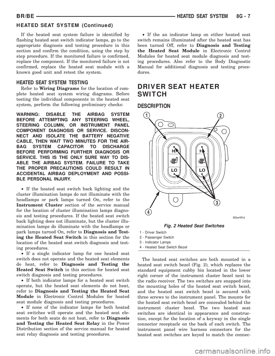
The heated seat switches are both mounted in a
heated seat switch bezel (Fig. 2), which replaces the
standard equipment cubby bin located in the lower
right corner of the instrument cluster bezel next to
the radio receiver. The two switches are snapped into
the mounting holes of the heated seat switch bezel,
and the heated seat switch bezel is secured with
three screws to the instrument panel. The mounts for
the heated seat switch bezel are concealed behind the
instrument cluster bezel. The two heated seat
switches are identical in appearance and construc-
tion, except for the location of a keyway in the single
connector receptacle on the back of each switch. The
instrument panel wire harness connectors for the
heated seat switches are keyed to match the connec-
Fig. 2 Heated Seat Switches
1 - Driver Switch
2 - Passenger Switch
3 - Indicator Lamps
4 - Heated Seat Switch Bezel
BR/BEHEATED SEAT SYSTEM 8G - 7
HEATED SEAT SYSTEM (Continued)
Page 462 of 2255
²Terminal number 30 is connected to battery volt-
age. For both the ASD and fuel pump relays, termi-
nal 30 is connected to battery voltage at all times.
²The PCM grounds the coil side of the relay
through terminal number 85.
²Terminal number 86 supplies voltage to the coil
side of the relay.
²When the PCM de-energizes the ASD and fuel
pump relays, terminal number 87A connects to termi-
nal 30. This is the Off position. In the off position,
voltage is not supplied to the rest of the circuit. Ter-
minal 87A is the center terminal on the relay.
²When the PCM energizes the ASD and fuel
pump relays, terminal 87 connects to terminal 30.
This is the On position. Terminal 87 supplies voltage
to the rest of the circuit.
The following procedure applies to the ASD and
fuel pump relays.
(1) Remove relay from connector before testing.
(2) With the relay removed from the vehicle, use
an ohmmeter to check the resistance between termi-
nals 85 and 86. The resistance should be 75 ohms +/-
5 ohms.
(3) Connect the ohmmeter between terminals 30
and 87A. The ohmmeter should show continuity
between terminals 30 and 87A.
(4) Connect the ohmmeter between terminals 87
and 30. The ohmmeter should not show continuity at
this time.
(5) Connect one end of a jumper wire (16 gauge or
smaller) to relay terminal 85. Connect the other end
of the jumper wire to the ground side of a 12 volt
power source.
(6) Connect one end of another jumper wire (16
gauge or smaller) to the power side of the 12 volt
power source.Do not attach the other end of the
jumper wire to the relay at this time.
WARNING: DO NOT ALLOW OHMMETER TO CON-
TACT TERMINALS 85 OR 86 DURING THIS TEST.
DAMAGE TO OHMMETER MAY RESULT.
(7) Attach the other end of the jumper wire to
relay terminal 86. This activates the relay. The ohm-
meter should now show continuity between relay ter-
minals 87 and 30. The ohmmeter should not show
continuity between relay terminals 87A and 30.
(8) Disconnect jumper wires.(9) Replace the relay if it did not pass the continu-
ity and resistance tests. If the relay passed the tests,
it operates properly. Check the remainder of the ASD
and fuel pump relay circuits. Refer to 8, Wiring Dia-
grams.
REMOVAL
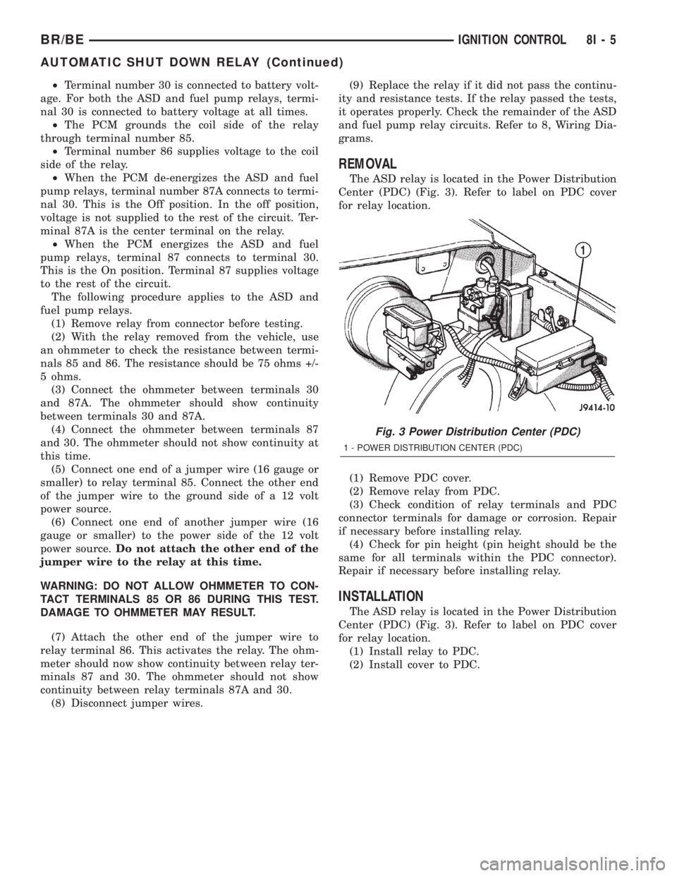
The ASD relay is located in the Power Distribution
Center (PDC) (Fig. 3). Refer to label on PDC cover
for relay location.
(1) Remove PDC cover.
(2) Remove relay from PDC.
(3) Check condition of relay terminals and PDC
connector terminals for damage or corrosion. Repair
if necessary before installing relay.
(4) Check for pin height (pin height should be the
same for all terminals within the PDC connector).
Repair if necessary before installing relay.
INSTALLATION
The ASD relay is located in the Power Distribution
Center (PDC) (Fig. 3). Refer to label on PDC cover
for relay location.
(1) Install relay to PDC.
(2) Install cover to PDC.
Fig. 3 Power Distribution Center (PDC)
1 - POWER DISTRIBUTION CENTER (PDC)
BR/BEIGNITION CONTROL 8I - 5
AUTOMATIC SHUT DOWN RELAY (Continued)
Page 472 of 2255
IGNITION COIL
DESCRIPTION
DESCRIPTION - 5.9L
A single ignition coil is used. The coil is not oil
filled. The coil windings are embedded in an epoxy
compound. This provides heat and vibration resis-
tance that allows the coil to be mounted on the
engine.
DESCRIPTION - 8.0L
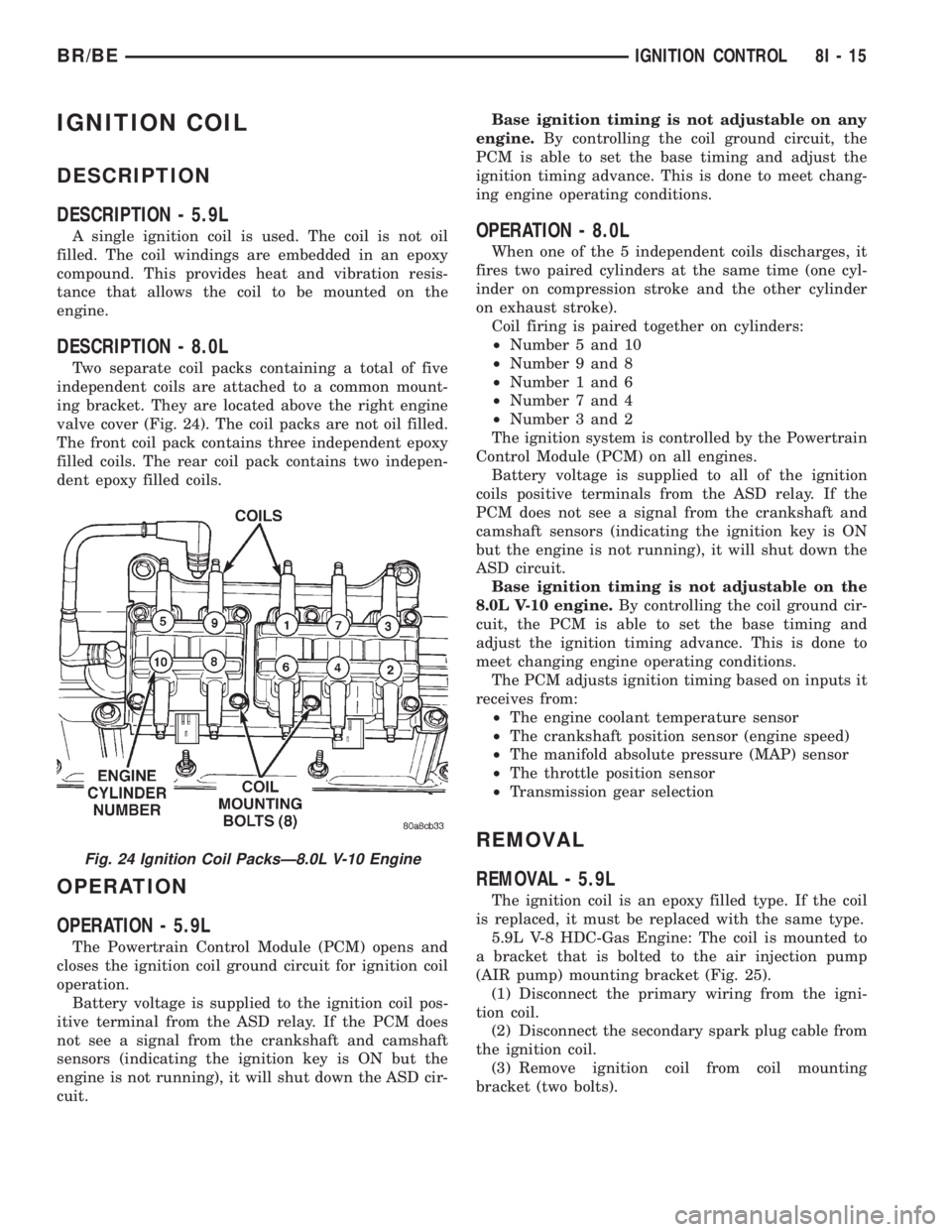
Two separate coil packs containing a total of five
independent coils are attached to a common mount-
ing bracket. They are located above the right engine
valve cover (Fig. 24). The coil packs are not oil filled.
The front coil pack contains three independent epoxy
filled coils. The rear coil pack contains two indepen-
dent epoxy filled coils.
OPERATION
OPERATION - 5.9L
The Powertrain Control Module (PCM) opens and
closes the ignition coil ground circuit for ignition coil
operation.
Battery voltage is supplied to the ignition coil pos-
itive terminal from the ASD relay. If the PCM does
not see a signal from the crankshaft and camshaft
sensors (indicating the ignition key is ON but the
engine is not running), it will shut down the ASD cir-
cuit.Base ignition timing is not adjustable on any
engine.By controlling the coil ground circuit, the
PCM is able to set the base timing and adjust the
ignition timing advance. This is done to meet chang-
ing engine operating conditions.
OPERATION - 8.0L
When one of the 5 independent coils discharges, it
fires two paired cylinders at the same time (one cyl-
inder on compression stroke and the other cylinder
on exhaust stroke).
Coil firing is paired together on cylinders:
²Number 5 and 10
²Number 9 and 8
²Number 1 and 6
²Number 7 and 4
²Number 3 and 2
The ignition system is controlled by the Powertrain
Control Module (PCM) on all engines.
Battery voltage is supplied to all of the ignition
coils positive terminals from the ASD relay. If the
PCM does not see a signal from the crankshaft and
camshaft sensors (indicating the ignition key is ON
but the engine is not running), it will shut down the
ASD circuit.
Base ignition timing is not adjustable on the
8.0L V-10 engine.By controlling the coil ground cir-
cuit, the PCM is able to set the base timing and
adjust the ignition timing advance. This is done to
meet changing engine operating conditions.
The PCM adjusts ignition timing based on inputs it
receives from:
²The engine coolant temperature sensor
²The crankshaft position sensor (engine speed)
²The manifold absolute pressure (MAP) sensor
²The throttle position sensor
²Transmission gear selection
REMOVAL
REMOVAL - 5.9L
The ignition coil is an epoxy filled type. If the coil
is replaced, it must be replaced with the same type.
5.9L V-8 HDC-Gas Engine: The coil is mounted to
a bracket that is bolted to the air injection pump
(AIR pump) mounting bracket (Fig. 25).
(1) Disconnect the primary wiring from the igni-
tion coil.
(2) Disconnect the secondary spark plug cable from
the ignition coil.
(3) Remove ignition coil from coil mounting
bracket (two bolts).
Fig. 24 Ignition Coil PacksÐ8.0L V-10 Engine
BR/BEIGNITION CONTROL 8I - 15