2002 CHRYSLER VOYAGER Starter
[x] Cancel search: StarterPage 1414 of 2399
VALVE TIMING
STANDARD PROCEDURE - LOCKING ENGINE
90É AFTER TDC
(1) Disconnect negative battery cable.
(2) Remove starter motor (Refer to 8 - ELECTRI-
CAL/STARTING/STARTER MOTOR - REMOVAL).
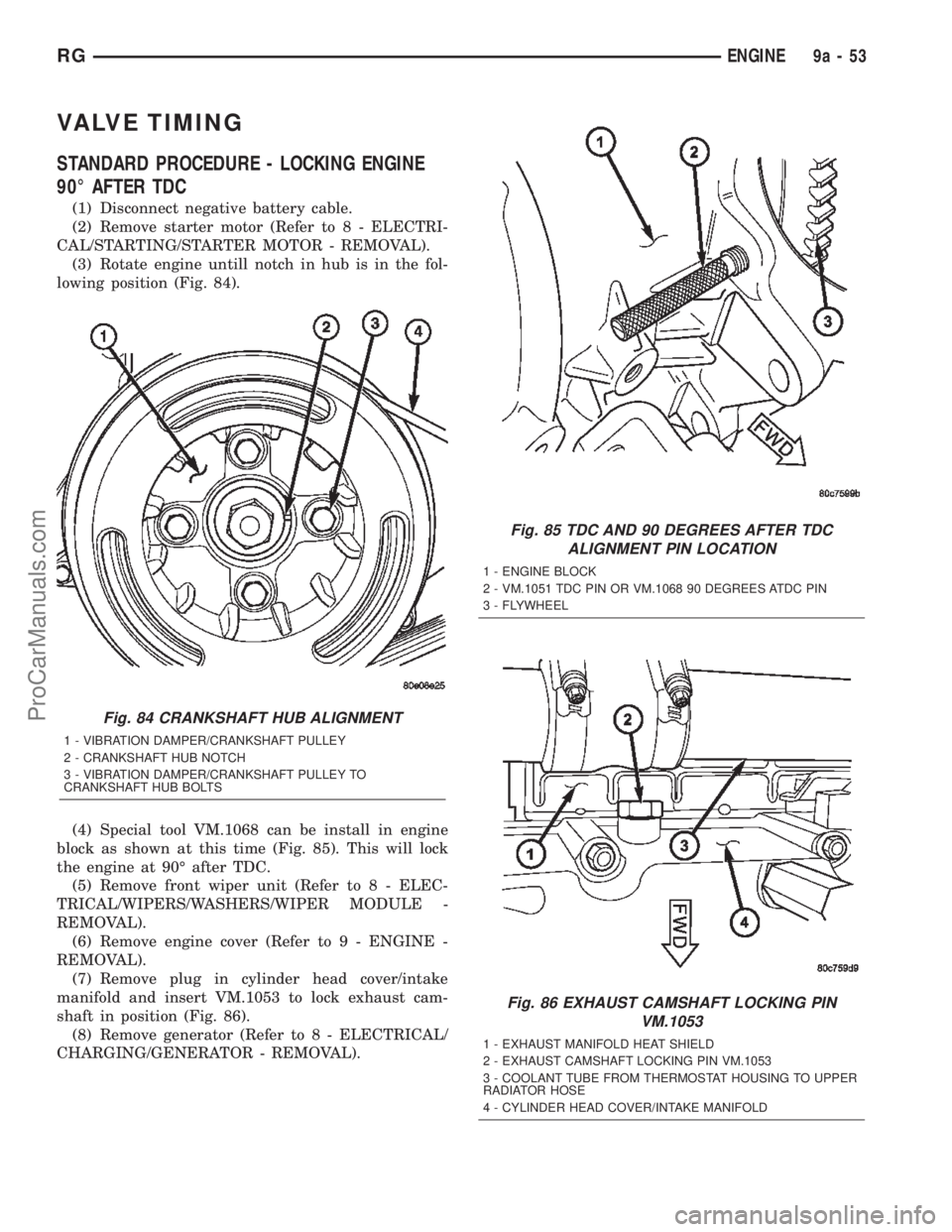
(3) Rotate engine untill notch in hub is in the fol-
lowing position (Fig. 84).
(4) Special tool VM.1068 can be install in engine
block as shown at this time (Fig. 85). This will lock
the engine at 90É after TDC.
(5) Remove front wiper unit (Refer to 8 - ELEC-
TRICAL/WIPERS/WASHERS/WIPER MODULE -
REMOVAL).
(6) Remove engine cover (Refer to 9 - ENGINE -
REMOVAL).
(7) Remove plug in cylinder head cover/intake
manifold and insert VM.1053 to lock exhaust cam-
shaft in position (Fig. 86).
(8) Remove generator (Refer to 8 - ELECTRICAL/
CHARGING/GENERATOR - REMOVAL).
Fig. 84 CRANKSHAFT HUB ALIGNMENT
1 - VIBRATION DAMPER/CRANKSHAFT PULLEY
2 - CRANKSHAFT HUB NOTCH
3 - VIBRATION DAMPER/CRANKSHAFT PULLEY TO
CRANKSHAFT HUB BOLTS
Fig. 85 TDC AND 90 DEGREES AFTER TDC
ALIGNMENT PIN LOCATION
1 - ENGINE BLOCK
2 - VM.1051 TDC PIN OR VM.1068 90 DEGREES ATDC PIN
3 - FLYWHEEL
Fig. 86 EXHAUST CAMSHAFT LOCKING PIN
VM.1053
1 - EXHAUST MANIFOLD HEAT SHIELD
2 - EXHAUST CAMSHAFT LOCKING PIN VM.1053
3 - COOLANT TUBE FROM THERMOSTAT HOUSING TO UPPER
RADIATOR HOSE
4 - CYLINDER HEAD COVER/INTAKE MANIFOLD
RGENGINE9a-53
ProCarManuals.com
Page 1415 of 2399
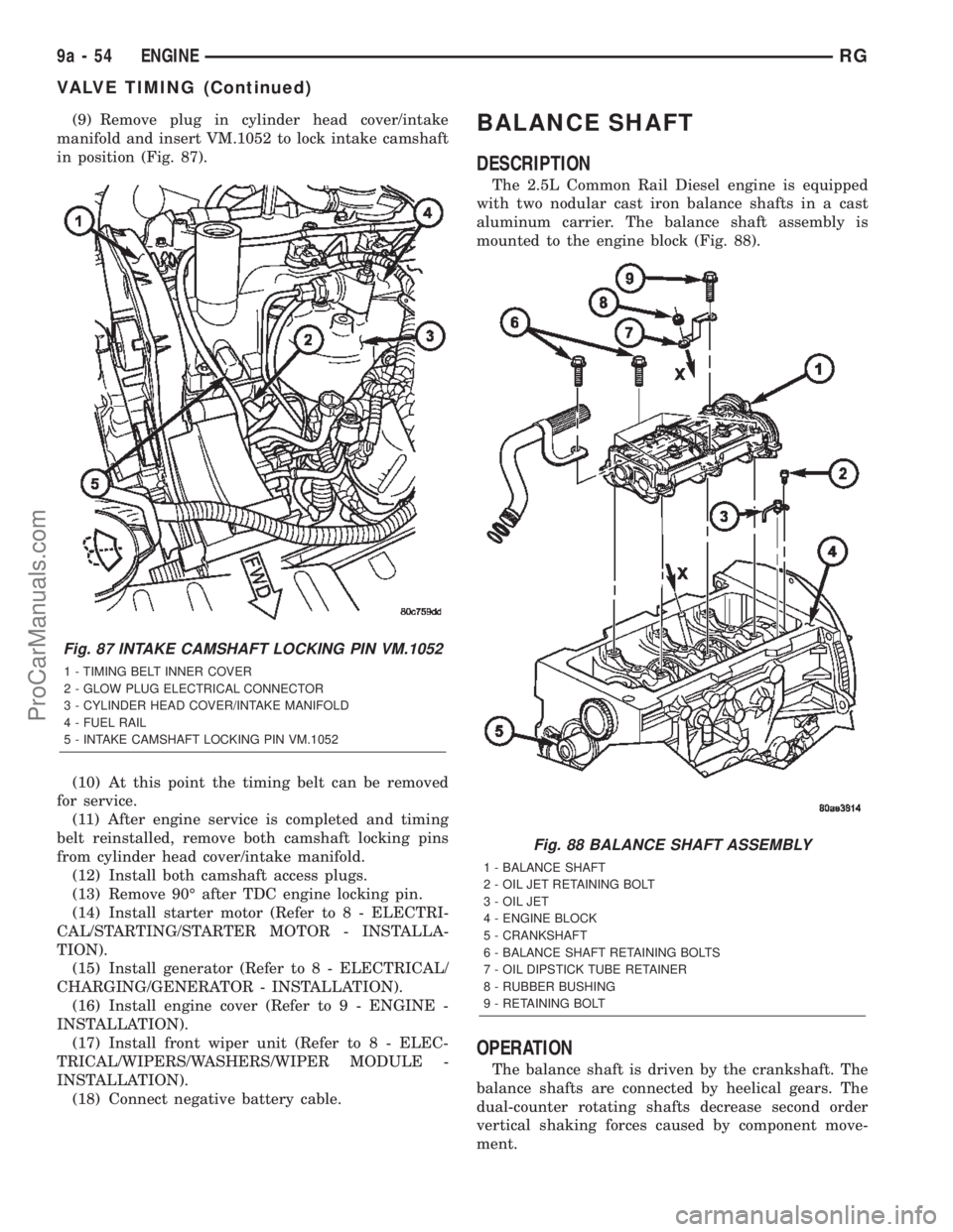
(9) Remove plug in cylinder head cover/intake
manifold and insert VM.1052 to lock intake camshaft
in position (Fig. 87).
(10) At this point the timing belt can be removed
for service.
(11) After engine service is completed and timing
belt reinstalled, remove both camshaft locking pins
from cylinder head cover/intake manifold.
(12) Install both camshaft access plugs.
(13) Remove 90É after TDC engine locking pin.
(14) Install starter motor (Refer to 8 - ELECTRI-
CAL/STARTING/STARTER MOTOR - INSTALLA-
TION).
(15) Install generator (Refer to 8 - ELECTRICAL/
CHARGING/GENERATOR - INSTALLATION).
(16) Install engine cover (Refer to 9 - ENGINE -
INSTALLATION).
(17) Install front wiper unit (Refer to 8 - ELEC-
TRICAL/WIPERS/WASHERS/WIPER MODULE -
INSTALLATION).
(18) Connect negative battery cable.BALANCE SHAFT
DESCRIPTION
The 2.5L Common Rail Diesel engine is equipped
with two nodular cast iron balance shafts in a cast
aluminum carrier. The balance shaft assembly is
mounted to the engine block (Fig. 88).
OPERATION
The balance shaft is driven by the crankshaft. The
balance shafts are connected by heelical gears. The
dual-counter rotating shafts decrease second order
vertical shaking forces caused by component move-
ment.
Fig. 87 INTAKE CAMSHAFT LOCKING PIN VM.1052
1 - TIMING BELT INNER COVER
2 - GLOW PLUG ELECTRICAL CONNECTOR
3 - CYLINDER HEAD COVER/INTAKE MANIFOLD
4 - FUEL RAIL
5 - INTAKE CAMSHAFT LOCKING PIN VM.1052
Fig. 88 BALANCE SHAFT ASSEMBLY
1 - BALANCE SHAFT
2 - OIL JET RETAINING BOLT
3 - OIL JET
4 - ENGINE BLOCK
5 - CRANKSHAFT
6 - BALANCE SHAFT RETAINING BOLTS
7 - OIL DIPSTICK TUBE RETAINER
8 - RUBBER BUSHING
9 - RETAINING BOLT
9a - 54 ENGINERG
VALVE TIMING (Continued)
ProCarManuals.com
Page 1469 of 2399
1 second. Therefore, battery voltage is not supplied to
the fuel pump, ignition coil, fuel injectors and heated
oxygen sensors.
ENGINE START-UP MODE
This is an OPEN LOOP mode. If the vehicle is in
park or neutral (automatic transaxles) or the clutch
pedal is depressed (manual transaxles) the ignition
switch energizes the starter relay. The following
actions occur when the starter motor is engaged.
²If the PCM receives the camshaft position sensor
and crankshaft position sensor signals, it energizes
the Auto Shutdown (ASD) relay and fuel pump relay.
If the PCM does not receive both signals within
approximately one second, it will not energize the
ASD relay and fuel pump relay. The ASD and fuel
pump relays supply battery voltage to the fuel pump,
fuel injectors, ignition coil, (EGR solenoid and PCV
heater if equipped) and heated oxygen sensors.
²The PCM energizes the injectors (on the 69É
degree falling edge) for a calculated pulse width until
it determines crankshaft position from the camshaft
position sensor and crankshaft position sensor sig-
nals. The PCM determines crankshaft position within
1 engine revolution.
²After determining crankshaft position, the PCM
begins energizing the injectors in sequence. It adjusts
injector pulse width and controls injector synchroni-
zation by turning the individual ground paths to the
injectors On and Off.
²When the engine idles within 64 RPM of its
target RPM, the PCM compares current MAP sensor
value with the atmospheric pressure value received
during the Ignition Switch On (zero RPM) mode.
Once the ASD and fuel pump relays have been
energized, the PCM determines injector pulse width
based on the following:
²MAP
²Engine RPM
²Battery voltage
²Engine coolant temperature
²Inlet/Intake air temperature (IAT)
²Throttle position
²The number of engine revolutions since cranking
was initiated
During Start-up the PCM maintains ignition tim-
ing at 9É BTDC.
ENGINE WARM-UP MODE
This is an OPEN LOOP mode. The following inputs
are received by the PCM:
²Manifold Absolute Pressure (MAP)
²Crankshaft position (engine speed)
²Engine coolant temperature
²Inlet/Intake air temperature (IAT)
²Camshaft position²Knock sensor
²Throttle position
²A/C switch
²Battery voltage
²Vehicle speed
²Speed control
²O2 sensors
The PCM adjusts injector pulse width and controls
injector synchronization by turning the individual
ground paths to the injectors On and Off.
The PCM adjusts ignition timing and engine idle
speed. Engine idle speed is adjusted through the idle
air control motor.
CRUISE OR IDLE MODE
When the engine is at operating temperature this
is a CLOSED LOOP mode. During cruising or idle
the following inputs are received by the PCM:
²Manifold absolute pressure
²Crankshaft position (engine speed)
²Inlet/Intake air temperature
²Engine coolant temperature
²Camshaft position
²Knock sensor
²Throttle position
²Exhaust gas oxygen content
²A/C control positions
²Battery voltage
²Vehicle speed
The PCM adjusts injector pulse width and controls
injector synchronization by turning the individual
ground paths to the injectors On and Off.
The PCM adjusts engine idle speed and ignition
timing. The PCM adjusts the air/fuel ratio according
to the oxygen content in the exhaust gas (measured
by the upstream and downstream heated oxygen sen-
sor).
The PCM monitors for engine misfire. During
active misfire and depending on the severity, the
PCM either continuously illuminates or flashes the
malfunction indicator lamp (Check Engine light on
instrument panel). Also, the PCM stores an engine
misfire DTC in memory, if 2nd trip with fault.
The PCM performs several diagnostic routines.
They include:
²Oxygen sensor monitor
²Downstream heated oxygen sensor diagnostics
during open loop operation (except for shorted)
²Fuel system monitor
²EGR monitor (if equipped)
²Purge system monitor
²Catalyst efficiency monitor
²All inputs monitored for proper voltage range,
rationality.
²All monitored components (refer to the Emission
section for On-Board Diagnostics).
14 - 18 FUEL INJECTIONRS
FUEL INJECTION (Continued)
ProCarManuals.com
Page 1592 of 2399
DIAGNOSIS AND TESTING - TORQUE
CONVERTER HOUSING FLUID LEAKAGE
When diagnosing converter housing fluid leaks,
three actions must be taken before repair:
(1) Verify proper transmission fluid level.
(2) Verify that the leak originates from the con-
verter housing area and is transmission fluid.
(3) Determine the true source of the leak.
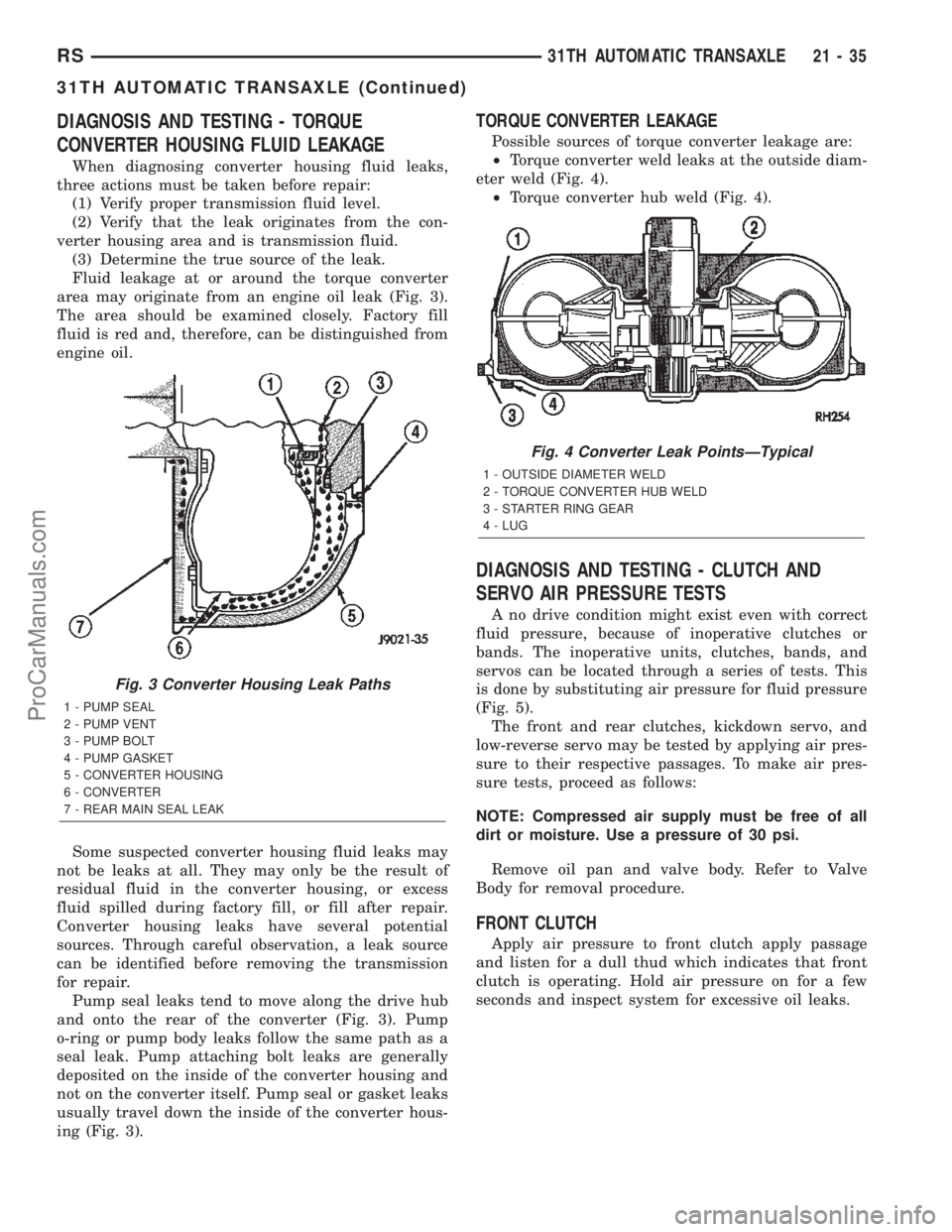
Fluid leakage at or around the torque converter
area may originate from an engine oil leak (Fig. 3).
The area should be examined closely. Factory fill
fluid is red and, therefore, can be distinguished from
engine oil.
Some suspected converter housing fluid leaks may
not be leaks at all. They may only be the result of
residual fluid in the converter housing, or excess
fluid spilled during factory fill, or fill after repair.
Converter housing leaks have several potential
sources. Through careful observation, a leak source
can be identified before removing the transmission
for repair.
Pump seal leaks tend to move along the drive hub
and onto the rear of the converter (Fig. 3). Pump
o-ring or pump body leaks follow the same path as a
seal leak. Pump attaching bolt leaks are generally
deposited on the inside of the converter housing and
not on the converter itself. Pump seal or gasket leaks
usually travel down the inside of the converter hous-
ing (Fig. 3).
TORQUE CONVERTER LEAKAGE
Possible sources of torque converter leakage are:
²Torque converter weld leaks at the outside diam-
eter weld (Fig. 4).
²Torque converter hub weld (Fig. 4).
DIAGNOSIS AND TESTING - CLUTCH AND
SERVO AIR PRESSURE TESTS
A no drive condition might exist even with correct
fluid pressure, because of inoperative clutches or
bands. The inoperative units, clutches, bands, and
servos can be located through a series of tests. This
is done by substituting air pressure for fluid pressure
(Fig. 5).
The front and rear clutches, kickdown servo, and
low-reverse servo may be tested by applying air pres-
sure to their respective passages. To make air pres-
sure tests, proceed as follows:
NOTE: Compressed air supply must be free of all
dirt or moisture. Use a pressure of 30 psi.
Remove oil pan and valve body. Refer to Valve
Body for removal procedure.
FRONT CLUTCH
Apply air pressure to front clutch apply passage
and listen for a dull thud which indicates that front
clutch is operating. Hold air pressure on for a few
seconds and inspect system for excessive oil leaks.
Fig. 3 Converter Housing Leak Paths
1 - PUMP SEAL
2 - PUMP VENT
3 - PUMP BOLT
4 - PUMP GASKET
5 - CONVERTER HOUSING
6 - CONVERTER
7 - REAR MAIN SEAL LEAK
Fig. 4 Converter Leak PointsÐTypical
1 - OUTSIDE DIAMETER WELD
2 - TORQUE CONVERTER HUB WELD
3 - STARTER RING GEAR
4 - LUG
RS31TH AUTOMATIC TRANSAXLE21-35
31TH AUTOMATIC TRANSAXLE (Continued)
ProCarManuals.com
Page 1595 of 2399
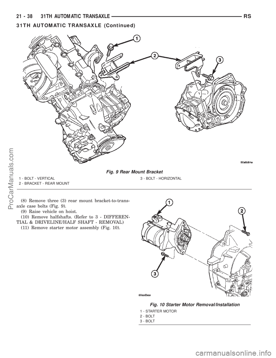
(8) Remove three (3) rear mount bracket-to-trans-
axle case bolts (Fig. 9).
(9) Raise vehicle on hoist.
(10) Remove halfshafts. (Refer to 3 - DIFFEREN-
TIAL & DRIVELINE/HALF SHAFT - REMOVAL)
(11) Remove starter motor assembly (Fig. 10).
Fig. 9 Rear Mount Bracket
1 - BOLT - VERTICAL
2 - BRACKET - REAR MOUNT3 - BOLT - HORIZONTAL
Fig. 10 Starter Motor Removal/Installation
1 - STARTER MOTOR
2 - BOLT
3 - BOLT
21 - 38 31TH AUTOMATIC TRANSAXLERS
31TH AUTOMATIC TRANSAXLE (Continued)
ProCarManuals.com
Page 1619 of 2399
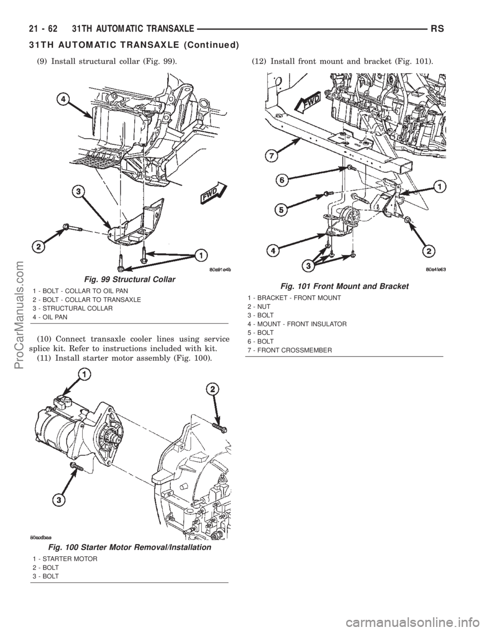
(9) Install structural collar (Fig. 99).
(10) Connect transaxle cooler lines using service
splice kit. Refer to instructions included with kit.
(11) Install starter motor assembly (Fig. 100).(12) Install front mount and bracket (Fig. 101).
Fig. 99 Structural Collar
1 - BOLT - COLLAR TO OIL PAN
2 - BOLT - COLLAR TO TRANSAXLE
3 - STRUCTURAL COLLAR
4 - OIL PAN
Fig. 100 Starter Motor Removal/Installation
1 - STARTER MOTOR
2 - BOLT
3 - BOLT
Fig. 101 Front Mount and Bracket
1 - BRACKET - FRONT MOUNT
2 - NUT
3 - BOLT
4 - MOUNT - FRONT INSULATOR
5 - BOLT
6 - BOLT
7 - FRONT CROSSMEMBER
21 - 62 31TH AUTOMATIC TRANSAXLERS
31TH AUTOMATIC TRANSAXLE (Continued)
ProCarManuals.com
Page 1631 of 2399
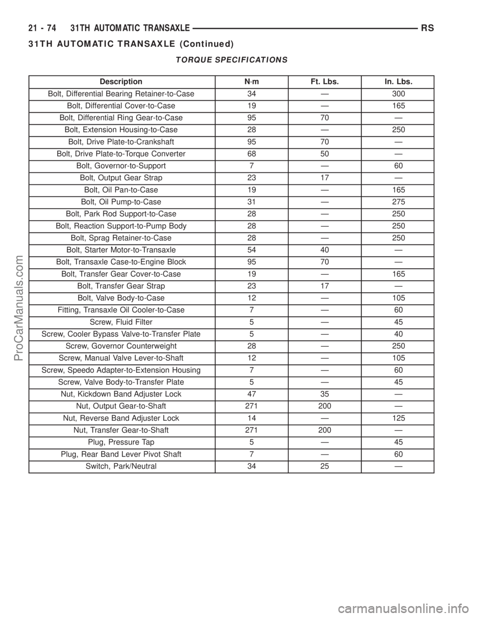
TORQUE SPECIFICATIONS
Description N´m Ft. Lbs. In. Lbs.
Bolt, Differential Bearing Retainer-to-Case 34 Ð 300
Bolt, Differential Cover-to-Case 19 Ð 165
Bolt, Differential Ring Gear-to-Case 95 70 Ð
Bolt, Extension Housing-to-Case 28 Ð 250
Bolt, Drive Plate-to-Crankshaft 95 70 Ð
Bolt, Drive Plate-to-Torque Converter 68 50 Ð
Bolt, Governor-to-Support 7 Ð 60
Bolt, Output Gear Strap 23 17 Ð
Bolt, Oil Pan-to-Case 19 Ð 165
Bolt, Oil Pump-to-Case 31 Ð 275
Bolt, Park Rod Support-to-Case 28 Ð 250
Bolt, Reaction Support-to-Pump Body 28 Ð 250
Bolt, Sprag Retainer-to-Case 28 Ð 250
Bolt, Starter Motor-to-Transaxle 54 40 Ð
Bolt, Transaxle Case-to-Engine Block 95 70 Ð
Bolt, Transfer Gear Cover-to-Case 19 Ð 165
Bolt, Transfer Gear Strap 23 17 Ð
Bolt, Valve Body-to-Case 12 Ð 105
Fitting, Transaxle Oil Cooler-to-Case 7 Ð 60
Screw, Fluid Filter 5 Ð 45
Screw, Cooler Bypass Valve-to-Transfer Plate 5 Ð 40
Screw, Governor Counterweight 28 Ð 250
Screw, Manual Valve Lever-to-Shaft 12 Ð 105
Screw, Speedo Adapter-to-Extension Housing 7 Ð 60
Screw, Valve Body-to-Transfer Plate 5 Ð 45
Nut, Kickdown Band Adjuster Lock 47 35 Ð
Nut, Output Gear-to-Shaft 271 200 Ð
Nut, Reverse Band Adjuster Lock 14 Ð 125
Nut, Transfer Gear-to-Shaft 271 200 Ð
Plug, Pressure Tap 5 Ð 45
Plug, Rear Band Lever Pivot Shaft 7 Ð 60
Switch, Park/Neutral 34 25 Ð
21 - 74 31TH AUTOMATIC TRANSAXLERS
31TH AUTOMATIC TRANSAXLE (Continued)
ProCarManuals.com
Page 1635 of 2399
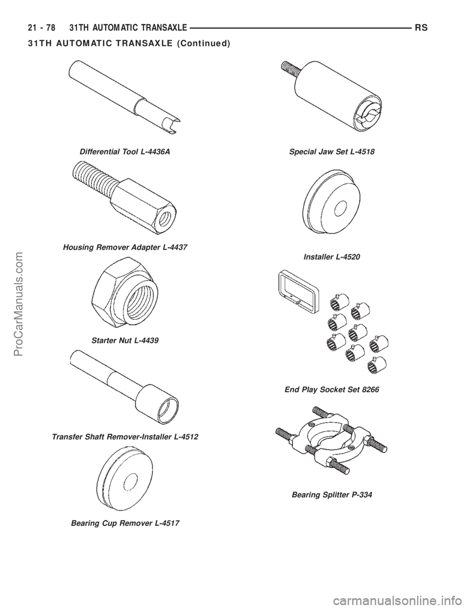
Differential Tool L-4436A
Housing Remover Adapter L-4437
Starter Nut L-4439
Transfer Shaft Remover-Installer L-4512
Bearing Cup Remover L-4517
Special Jaw Set L-4518
Installer L-4520
End Play Socket Set 8266
Bearing Splitter P-334
21 - 78 31TH AUTOMATIC TRANSAXLERS
31TH AUTOMATIC TRANSAXLE (Continued)
ProCarManuals.com