2002 CHRYSLER VOYAGER Starter
[x] Cancel search: StarterPage 1661 of 2399
ADJUSTMENTS
GEARSHIFT CABLE ADJUSTMENT
Lift and rotate the gearshift hand lever into the
park (P) gate position and remove the ignition key.
This confirms the shift lever is in the gated park (P)
position.
After confirming the park gate position, turn the
ignition switch . If the starter will operate, the park
gate position is correct. Move the shift lever into the
neutral (N) position. If the starter will operate in this
position, the linkage is properly adjusted. If the
starter fails to operate in either position, linkage
adjustment is required.
(1) Park the vehicle on level ground and set the
parking brake.
(2) Place the gearshift lever in park (P) gate posi-
tion and remove key.
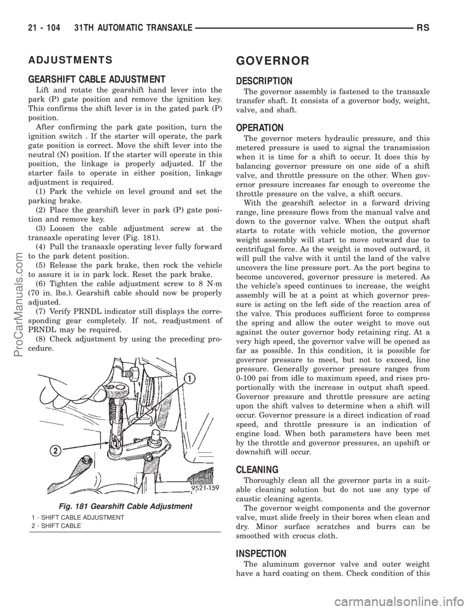
(3) Loosen the cable adjustment screw at the
transaxle operating lever (Fig. 181).
(4) Pull the transaxle operating lever fully forward
to the park detent position.
(5) Release the park brake, then rock the vehicle
to assure it is in park lock. Reset the park brake.
(6) Tighten the cable adjustment screw to 8 N´m
(70 in. lbs.). Gearshift cable should now be properly
adjusted.
(7) Verify PRNDL indicator still displays the corre-
sponding gear completely. If not, readjustment of
PRNDL may be required.
(8) Check adjustment by using the preceding pro-
cedure.
GOVERNOR
DESCRIPTION
The governor assembly is fastened to the transaxle
transfer shaft. It consists of a governor body, weight,
valve, and shaft.
OPERATION
The governor meters hydraulic pressure, and this
metered pressure is used to signal the transmission
when it is time for a shift to occur. It does this by
balancing governor pressure on one side of a shift
valve, and throttle pressure on the other. When gov-
ernor pressure increases far enough to overcome the
throttle pressure on the valve, a shift occurs.
With the gearshift selector in a forward driving
range, line pressure flows from the manual valve and
down to the governor valve. When the output shaft
starts to rotate with vehicle motion, the governor
weight assembly will start to move outward due to
centrifugal force. As the weight is moved outward, it
will pull the valve with it until the land of the valve
uncovers the line pressure port. As the port begins to
become uncovered, governor pressure is metered. As
the vehicle's speed continues to increase, the weight
assembly will be at a point at which governor pres-
sure is acting on the left side of the reaction area of
the valve. This produces sufficient force to compress
the spring and allow the outer weight to move out
against the outer governor body retaining ring. At a
very high speed, the governor valve will be opened as
far as possible. In this condition, it is possible for
governor pressure to meet, but not to exceed, line
pressure. Generally governor pressure ranges from
0-100 psi from idle to maximum speed, and rises pro-
portionally with the increase in output shaft speed.
Governor pressure and throttle pressure are acting
upon the shift valves to determine when a shift will
occur. Governor pressure is a direct indication of road
speed, and throttle pressure is an indication of
engine load. When both parameters have been met
by the throttle and governor pressures, an upshift or
downshift will occur.
CLEANING
Thoroughly clean all the governor parts in a suit-
able cleaning solution but do not use any type of
caustic cleaning agents.
The governor weight components and the governor
valve, must slide freely in their bores when clean and
dry. Minor surface scratches and burrs can be
smoothed with crocus cloth.
INSPECTION
The aluminum governor valve and outer weight
have a hard coating on them. Check condition of this
Fig. 181 Gearshift Cable Adjustment
1 - SHIFT CABLE ADJUSTMENT
2 - SHIFT CABLE
21 - 104 31TH AUTOMATIC TRANSAXLERS
ProCarManuals.com
Page 1664 of 2399
(5) Reinstall gears to pump body and measure
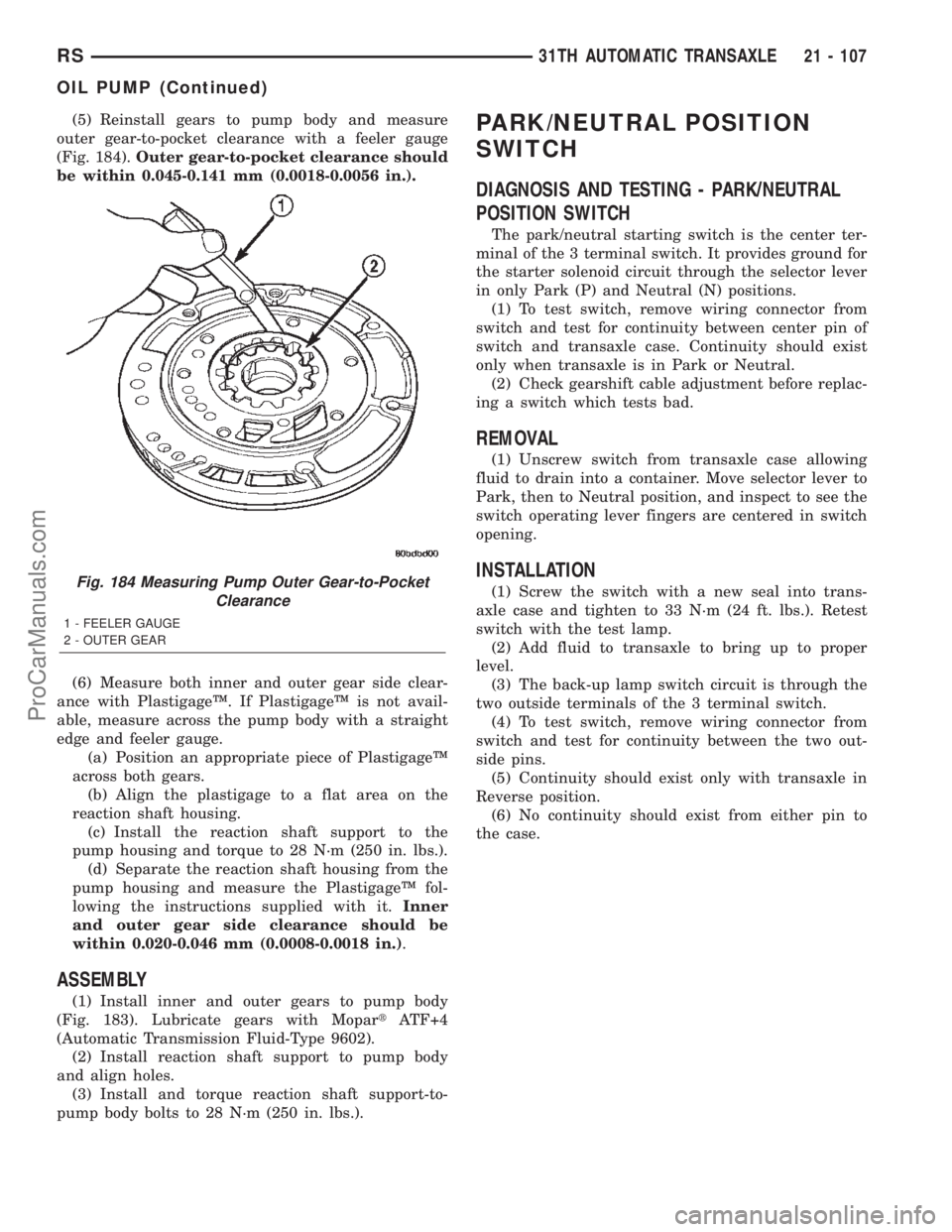
outer gear-to-pocket clearance with a feeler gauge
(Fig. 184).Outer gear-to-pocket clearance should
be within 0.045-0.141 mm (0.0018-0.0056 in.).
(6) Measure both inner and outer gear side clear-
ance with PlastigageŸ. If PlastigageŸ is not avail-
able, measure across the pump body with a straight
edge and feeler gauge.
(a) Position an appropriate piece of PlastigageŸ
across both gears.
(b) Align the plastigage to a flat area on the
reaction shaft housing.
(c) Install the reaction shaft support to the
pump housing and torque to 28 N´m (250 in. lbs.).
(d) Separate the reaction shaft housing from the
pump housing and measure the PlastigageŸ fol-
lowing the instructions supplied with it.Inner
and outer gear side clearance should be
within 0.020-0.046 mm (0.0008-0.0018 in.).
ASSEMBLY
(1) Install inner and outer gears to pump body
(Fig. 183). Lubricate gears with MopartATF+4
(Automatic Transmission Fluid-Type 9602).
(2) Install reaction shaft support to pump body
and align holes.
(3) Install and torque reaction shaft support-to-
pump body bolts to 28 N´m (250 in. lbs.).
PARK/NEUTRAL POSITION
SWITCH
DIAGNOSIS AND TESTING - PARK/NEUTRAL
POSITION SWITCH
The park/neutral starting switch is the center ter-
minal of the 3 terminal switch. It provides ground for
the starter solenoid circuit through the selector lever
in only Park (P) and Neutral (N) positions.
(1) To test switch, remove wiring connector from
switch and test for continuity between center pin of
switch and transaxle case. Continuity should exist
only when transaxle is in Park or Neutral.
(2) Check gearshift cable adjustment before replac-
ing a switch which tests bad.
REMOVAL
(1) Unscrew switch from transaxle case allowing
fluid to drain into a container. Move selector lever to
Park, then to Neutral position, and inspect to see the
switch operating lever fingers are centered in switch
opening.
INSTALLATION
(1) Screw the switch with a new seal into trans-
axle case and tighten to 33 N´m (24 ft. lbs.). Retest
switch with the test lamp.
(2) Add fluid to transaxle to bring up to proper
level.
(3) The back-up lamp switch circuit is through the
two outside terminals of the 3 terminal switch.
(4) To test switch, remove wiring connector from
switch and test for continuity between the two out-
side pins.
(5) Continuity should exist only with transaxle in
Reverse position.
(6) No continuity should exist from either pin to
the case.Fig. 184 Measuring Pump Outer Gear-to-Pocket
Clearance
1 - FEELER GAUGE
2 - OUTER GEAR
RS31TH AUTOMATIC TRANSAXLE21 - 107
OIL PUMP (Continued)
ProCarManuals.com
Page 1726 of 2399
Converter housing leaks have several potential
sources. Through careful observation, a leak source
can be identified before removing the transmission
for repair.
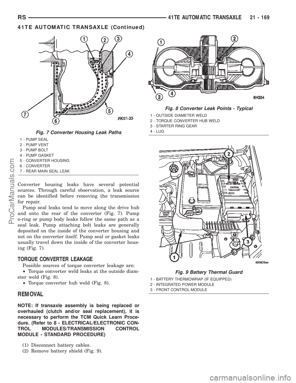
Pump seal leaks tend to move along the drive hub
and onto the rear of the converter (Fig. 7). Pump
o-ring or pump body leaks follow the same path as a
seal leak. Pump attaching bolt leaks are generally
deposited on the inside of the converter housing and
not on the converter itself. Pump seal or gasket leaks
usually travel down the inside of the converter hous-
ing (Fig. 7).
TORQUE CONVERTER LEAKAGE
Possible sources of torque converter leakage are:
²Torque converter weld leaks at the outside diam-
eter weld (Fig. 8).
²Torque converter hub weld (Fig. 8).
REMOVAL
NOTE: If transaxle assembly is being replaced or
overhauled (clutch and/or seal replacement), it is
necessary to perform the TCM Quick Learn Proce-
dure. (Refer to 8 - ELECTRICAL/ELECTRONIC CON-
TROL MODULES/TRANSMISSION CONTROL
MODULE - STANDARD PROCEDURE)
(1) Disconnect battery cables.
(2) Remove battery shield (Fig. 9).
Fig. 7 Converter Housing Leak Paths
1 - PUMP SEAL
2 - PUMP VENT
3 - PUMP BOLT
4 - PUMP GASKET
5 - CONVERTER HOUSING
6 - CONVERTER
7 - REAR MAIN SEAL LEAK
Fig. 8 Converter Leak Points - Typical
1 - OUTSIDE DIAMETER WELD
2 - TORQUE CONVERTER HUB WELD
3 - STARTER RING GEAR
4 - LUG
Fig. 9 Battery Thermal Guard
1 - BATTERY THERMOWRAP (IF EQUIPPED)
2 - INTEGRATED POWER MODULE
3 - FRONT CONTROL MODULE
RS41TE AUTOMATIC TRANSAXLE21 - 169
41TE AUTOMATIC TRANSAXLE (Continued)
ProCarManuals.com
Page 1728 of 2399
(18) AWD models: Remove power transfer unit.
(Refer to 21 - TRANSMISSION/TRANSAXLE/
POWER TRANSFER UNIT - REMOVAL)
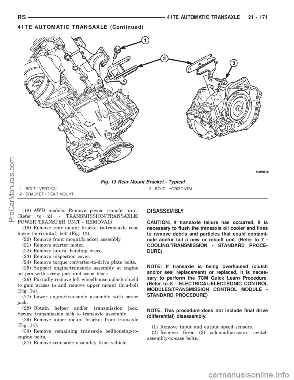
(19) Remove rear mount bracket-to-transaxle case
lower (horizontal) bolt (Fig. 13).
(20) Remove front mount/bracket assembly.
(21) Remove starter motor.
(22) Remove lateral bending brace.
(23) Remove inspection cover.
(24) Remove torque converter-to-drive plate bolts.
(25) Support engine/transaxle assembly at engine
oil pan with screw jack and wood block.
(26) Partially remove left wheelhouse splash shield
to gain access to and remove upper mount thru-bolt
(Fig. 14).
(27) Lower engine/transaxle assembly with screw
jack.
(28) Obtain helper and/or transmission jack.
Secure transmission jack to transaxle assembly.
(29) Remove upper mount bracket from transaxle
(Fig. 14).
(30) Remove remaining transaxle bellhousing-to-
engine bolts.
(31) Remove transaxle assembly from vehicle.DISASSEMBLY
CAUTION: If transaxle failure has occurred, it is
necessary to flush the transaxle oil cooler and lines
to remove debris and particles that could contami-
nate and/or fail a new or rebuilt unit. (Refer to 7 -
COOLING/TRANSMISSION - STANDARD PROCE-
DURE)
NOTE: If transaxle is being overhauled (clutch
and/or seal replacement) or replaced, it is neces-
sary to perform the TCM Quick Learn Procedure.
(Refer to 8 - ELECTRICAL/ELECTRONIC CONTROL
MODULES/TRANSMISSION CONTROL MODULE -
STANDARD PROCEDURE)
NOTE: This procedure does not include final drive
(differential) disassembly.
(1) Remove input and output speed sensors.
(2) Remove three (3) solenoid/pressure switch
assembly-to-case bolts.
Fig. 13 Rear Mount Bracket - Typical
1 - BOLT - VERTICAL
2 - BRACKET - REAR MOUNT3 - BOLT - HORIZONTAL
RS41TE AUTOMATIC TRANSAXLE21 - 171
41TE AUTOMATIC TRANSAXLE (Continued)
ProCarManuals.com
Page 1770 of 2399
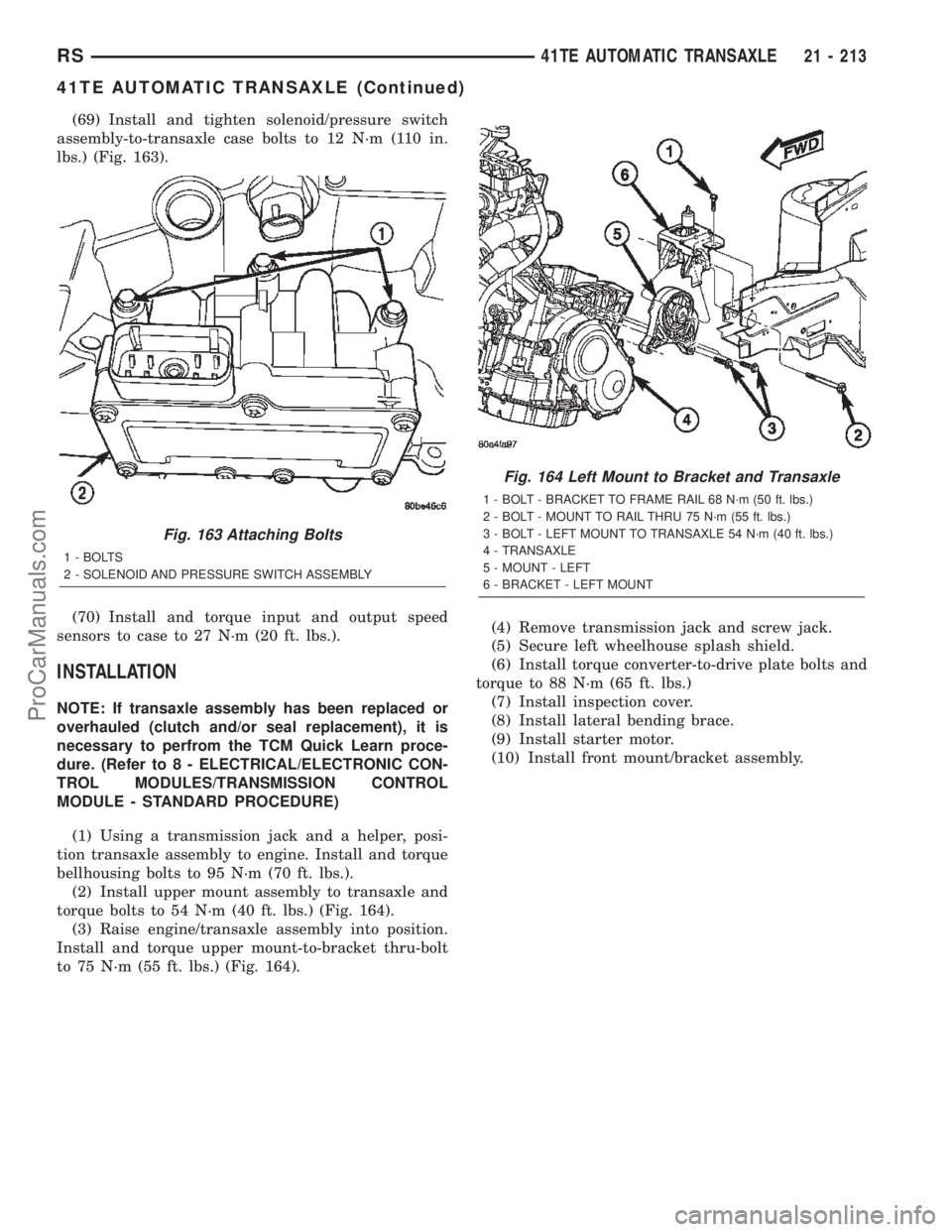
(69) Install and tighten solenoid/pressure switch
assembly-to-transaxle case bolts to 12 N´m (110 in.
lbs.) (Fig. 163).
(70) Install and torque input and output speed
sensors to case to 27 N´m (20 ft. lbs.).
INSTALLATION
NOTE: If transaxle assembly has been replaced or
overhauled (clutch and/or seal replacement), it is
necessary to perfrom the TCM Quick Learn proce-
dure. (Refer to 8 - ELECTRICAL/ELECTRONIC CON-
TROL MODULES/TRANSMISSION CONTROL
MODULE - STANDARD PROCEDURE)
(1) Using a transmission jack and a helper, posi-
tion transaxle assembly to engine. Install and torque
bellhousing bolts to 95 N´m (70 ft. lbs.).
(2) Install upper mount assembly to transaxle and
torque bolts to 54 N´m (40 ft. lbs.) (Fig. 164).
(3) Raise engine/transaxle assembly into position.
Install and torque upper mount-to-bracket thru-bolt
to 75 N´m (55 ft. lbs.) (Fig. 164).(4) Remove transmission jack and screw jack.
(5) Secure left wheelhouse splash shield.
(6) Install torque converter-to-drive plate bolts and
torque to 88 N´m (65 ft. lbs.)
(7) Install inspection cover.
(8) Install lateral bending brace.
(9) Install starter motor.
(10) Install front mount/bracket assembly.
Fig. 163 Attaching Bolts
1 - BOLTS
2 - SOLENOID AND PRESSURE SWITCH ASSEMBLY
Fig. 164 Left Mount to Bracket and Transaxle
1 - BOLT - BRACKET TO FRAME RAIL 68 N´m (50 ft. lbs.)
2 - BOLT - MOUNT TO RAIL THRU 75 N´m (55 ft. lbs.)
3 - BOLT - LEFT MOUNT TO TRANSAXLE 54 N´m (40 ft. lbs.)
4 - TRANSAXLE
5 - MOUNT - LEFT
6 - BRACKET - LEFT MOUNT
RS41TE AUTOMATIC TRANSAXLE21 - 213
41TE AUTOMATIC TRANSAXLE (Continued)
ProCarManuals.com
Page 1876 of 2399
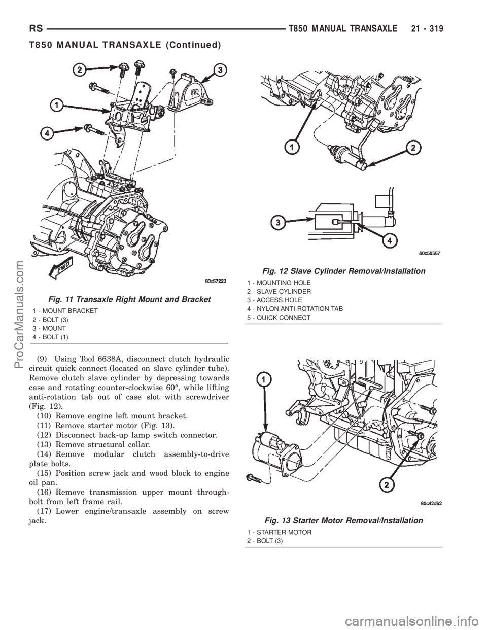
(9) Using Tool 6638A, disconnect clutch hydraulic
circuit quick connect (located on slave cylinder tube).
Remove clutch slave cylinder by depressing towards
case and rotating counter-clockwise 60É, while lifting
anti-rotation tab out of case slot with screwdriver
(Fig. 12).
(10) Remove engine left mount bracket.
(11) Remove starter motor (Fig. 13).
(12) Disconnect back-up lamp switch connector.
(13) Remove structural collar.
(14) Remove modular clutch assembly-to-drive
plate bolts.
(15) Position screw jack and wood block to engine
oil pan.
(16) Remove transmission upper mount through-
bolt from left frame rail.
(17) Lower engine/transaxle assembly on screw
jack.
Fig. 11 Transaxle Right Mount and Bracket
1 - MOUNT BRACKET
2 - BOLT (3)
3 - MOUNT
4 - BOLT (1)
Fig. 12 Slave Cylinder Removal/Installation
1 - MOUNTING HOLE
2 - SLAVE CYLINDER
3 - ACCESS HOLE
4 - NYLON ANTI-ROTATION TAB
5 - QUICK CONNECT
Fig. 13 Starter Motor Removal/Installation
1 - STARTER MOTOR
2 - BOLT (3)
RST850 MANUAL TRANSAXLE21 - 319
T850 MANUAL TRANSAXLE (Continued)
ProCarManuals.com
Page 1879 of 2399
(11) Raise vehicle on hoist.
(12) Remove front wheel/tires and halfshafts.
(13) Remove underbody splash shield.
(14) Drain transaxle fluid into suitable container.
(15) Remove front harness retainer and secure
harness out of way.
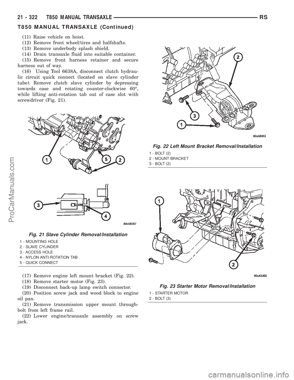
(16) Using Tool 6638A, disconnect clutch hydrau-
lic circuit quick connect (located on slave cylinder
tube). Remove clutch slave cylinder by depressing
towards case and rotating counter-clockwise 60É,
while lifting anti-rotation tab out of case slot with
screwdriver (Fig. 21).
(17) Remove engine left mount bracket (Fig. 22).
(18) Remove starter motor (Fig. 23).
(19) Disconnect back-up lamp switch connector.
(20) Position screw jack and wood block to engine
oil pan.
(21) Remove transmission upper mount through-
bolt from left frame rail.
(22) Lower engine/transaxle assembly on screw
jack.
Fig. 21 Slave Cylinder Removal/Installation
1 - MOUNTING HOLE
2 - SLAVE CYLINDER
3 - ACCESS HOLE
4 - NYLON ANTI-ROTATION TAB
5 - QUICK CONNECT
Fig. 22 Left Mount Bracket Removal/Installation
1 - BOLT (2)
2 - MOUNT BRACKET
3 - BOLT (2)
Fig. 23 Starter Motor Removal/Installation
1 - STARTER MOTOR
2 - BOLT (3)
21 - 322 T850 MANUAL TRANSAXLERS
T850 MANUAL TRANSAXLE (Continued)
ProCarManuals.com
Page 1895 of 2399
INSTALLATION
INSTALLATION - 2.4L GAS
(1) Install modular clutch assembly to transaxle.
Assemble transaxle to engine.
(2) Install and torque transaxle-to-engine bolts to
95 N´m (70 ft. lbs.).
(3) Raise transaxle/engine assembly into position
and install upper mount through-bolt. Torque
through-bolt to 75 N´m (55 ft. lbs.).
(4) Remove screw jack.
(5) Install and torque modular clutch assembly-to-
drive plate bolts to 88 N´m (65 ft. lbs.)
(6) Install structural collar.
(7) Connect back-up lamp switch connector.
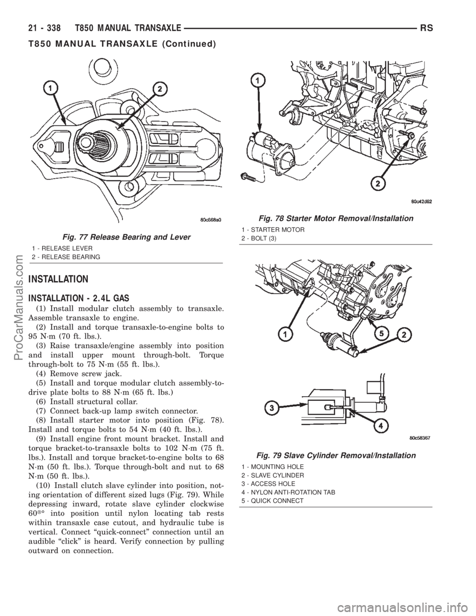
(8) Install starter motor into position (Fig. 78).
Install and torque bolts to 54 N´m (40 ft. lbs.).
(9) Install engine front mount bracket. Install and
torque bracket-to-transaxle bolts to 102 N´m (75 ft.
lbs.). Install and torque bracket-to-engine bolts to 68
N´m (50 ft. lbs.). Torque through-bolt and nut to 68
N´m (50 ft. lbs.).
(10) Install clutch slave cylinder into position, not-
ing orientation of different sized lugs (Fig. 79). While
depressing inward, rotate slave cylinder clockwise
60tÉ into position until nylon locating tab rests
within transaxle case cutout, and hydraulic tube is
vertical. Connect ªquick-connectº connection until an
audible ªclickº is heard. Verify connection by pulling
outward on connection.
Fig. 77 Release Bearing and Lever
1 - RELEASE LEVER
2 - RELEASE BEARING
Fig. 78 Starter Motor Removal/Installation
1 - STARTER MOTOR
2 - BOLT (3)
Fig. 79 Slave Cylinder Removal/Installation
1 - MOUNTING HOLE
2 - SLAVE CYLINDER
3 - ACCESS HOLE
4 - NYLON ANTI-ROTATION TAB
5 - QUICK CONNECT
21 - 338 T850 MANUAL TRANSAXLERS
T850 MANUAL TRANSAXLE (Continued)
ProCarManuals.com